Clock Recovery System for SAToP

The Clock Recovery System recovers the service clock using Adaptive Clock Recovery (ACR) and Differential Clock Recovery (DCR).

Finding Feature Information

Your software release may not support all the features documented in this module. For the latest caveats and feature information, see Bug Search Tool and the release notes for your platform and software release. To find information about the features documented in this module, and to see a list of the releases in which each feature is supported, see the feature information table.

Use Cisco Feature Navigator to find information about platform support and Cisco software image support. To access Cisco Feature Navigator, go to https://cfnng.cisco.com/. An account on Cisco.com is not required.

Information About Clock Recovery

Adaptive Clock Recovery (ACR)

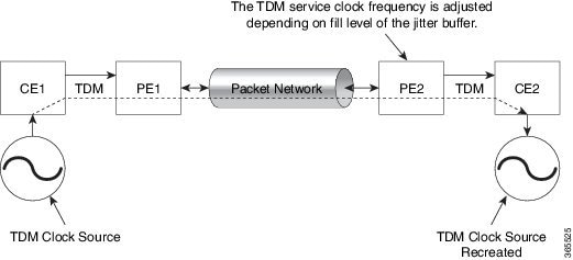
Adaptive Clock Recovery (ACR) is an averaging process that negates the effect of random packet delay variation and captures the average rate of transmission of the original bit stream. ACR recovers the original clock for a synchronous data stream from the actual payload of the data stream. In other words, a synchronous clock is derived from an asynchronous packet stream. ACR is a technique where the clock from the TDM domain is mapped through the packet domain, but is most commonly used for Circuit Emulation (CEM). ACR is supported on unframed and framed modes of SAToP.

Note

Framing type should be maintained same in all routers end to end.


Differential Clock Recovery (DCR)

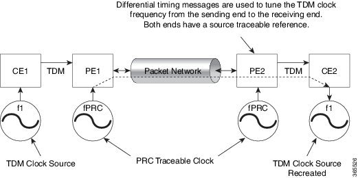
Differential Clock Recovery (DCR) is another technique used for Circuit Emulation (CEM) to recover clocks based on the difference between PE clocks. TDM clock frequency are tuned to receive differential timing messages from the sending end to the receiving end. A traceable clock is used at each end, which ensures the recovered clock is not affected by packet transfer. DCR is supported on unframed and framed modes of SAToP.

Note

Framing type should be maintained same in all routers end to end.


Explicit Pointer Adjustment Relay (EPAR)

A pointer management system is defined as part of the definition of SONET. If there is a frequency offset between the frame rate of the transport overhead and that of the SONET Synchronous Payload Envelope (SPE), the alignment of the SPE slips back periodically or advances in time through positive or negative stuffing. Similarly, if there is a frequency offset between the SPE rate and the VT rate it carries, the alignment of the VT slips back periodically or advances in time through positive or negative stuffing within the SPE. The emulation of this aspect of SONET network in pseudowire emulation network may be accomplished using EPAR feature.

EPAR uses N and P bits in CEP header to signal negative or positive pointer justification event. EPAR is supported on STS-1, STS-3C, STS-12C, STS-48C and VT-1.5 levels. N and P counters are added to communicate the signaling of the pointer events over CEP pseudowire.

Figure 1. EPAR

Effective Cisco IOS-XE Release 3.18 SP, EPAR is enabled by default.

Restrictions for EPAR

  • EPAR is applicable only for circuit emulation for SONET LO & HO paths and is not applicable for PDH.

  • EPAR is effective only when both ends of the pseudowire have access to a common timing reference.

Benefits of Clock Recovery

  • Customer-edge devices (CEs) can have different clock from that of the Provide-edge devices (PEs).

Scaling Information

IM Card

Pseudowires Supported (Number of Clocks Derived)

DS1

48

DS3

1344

1-Port OC192/STM-64 or 8-Port OC3/12/48/STM-1/-4/-16 Interface Module

2000

Prerequisites for Clock Recovery

  • The clock of interface modules must be used as service clock.

  • CEM must be configured before configuring the global clock recovery.

  • RTP must be enabled for DCR in CEM, as the differential clock information is transferred in the RTP header.

Restrictions for Clock Recovery

  • The reference clock source is used and locked to a single clock.

  • The clock ID should be unique for a particular interface module for ACR or DCR configuration.

  • When CEM group is configured, dynamic change in clock source is not allowed.

  • ACR clock configuration under each controller should be performed before configuring CEM group.

  • When ACR or DCR is configured and loopback network is applied on the same PDH (T1/E1), then the ACR or DCR mode configuration is removed to enable the loopback. The ACR or DCR should be configured again after the loopback maintenance activity.

Scale Restrictions

  • For the Cisco IOS XE Amsterdam 17.3.x release, a maximum of 5376 ACR and DCR session scale is supported on the Cisco 1-port OC-192 Interface module or 8-port Low Rate Interface Module (8-port SFP GE and 1-port 10GE IM with CEM, 10G). For releases before the Cisco IOS XE Amsterdam 17.3.1 release, only 2000 session are supported.

How to Configure Adaptive Clock Recovery (ACR)

Configuring ACR for OCn

Configuring ACR in Mode VT15 for SAToP

You must configure ACR for virtual tributary groups (VTG) mode. In this mode, a single STS-1 is divided into seven VTGs. Each VTG is then divided into four VT1.5, each carrying a T1.

To configure ACR in mode VT15 for Structure-Agnostic TDM over Packet (SAToP):

enable
configure terminal
controller sonet <bay>/<slot>/<port>
rate OC3
sts-1 <number>
mode vt-15
vtg 1 t1 cem 0 unframed
vtg 1 t1 1 clock source recovered 1
vtg <vtg_number> t1 <t1_number> cem-group < cem-group-no> unframed
vtg <vtg_number> t1 <t1_number> clock source recovered <clock-id>
exit
recovered-clock 0 <0-15> Subslot number
end

Verifying ACR in Mode VT15 for SAToP

Verifying ACR Configuration

Router# show running-config | section 0/4/0

controller MediaType 0/4/0
 mode sonet
controller SONET 0/4/0
 rate OC48
 no ais-shut
 framing sonet
 clock source internal
 !
 sts-1 1
  clock source internal
  mode vt-15	
  vtg 1 t1 1 clock source Recovered 0
  vtg 1 t1 1 framing unframed
  vtg 1 t1 1 cem-group 0 unframed

interface CEM0/4/0
 no ip address
 cem 0
!

Verifying Recovered Clock

Router# show recovered-clock

Recovered clock status for subslot 0/3
----------------------------------------
Clock    Type     Mode        CEM    Status         Frequency Offset(ppb)  Circuit-No
0        OCx-ds1  ADAPTIVE     0    ACQUIRED   n/a                             0/1/1/1 (Port/path/vtg/t1)
Router# show running-config | section recovered-clock 0 4

recovered-clock 0 4
 clock recovered 0 adaptive cem 0 0

Configuring ACR in mode T3 for SAToP

You must configure ACR in mode T3. Mode T3 is STS-1 or AU-4/TUG3 carrying an unchannelized (clear channel) T3.

enable
configure terminal
recovered-clock  <bay> <slot>
clock recovered <clock-id> adaptive cem <port-no> <cem-group-no>
controller sonet <bay>/<slot>/<port>
rate OC3
sts-1 <number>
mode t3
cem-group < cem-group-no> unframed
t3 clock source recovered <clock-id>

end

Verifying ACR in Mode T3 for SAToP

Verifying ACR Configuration

Router# show run | sec recovered
recovered-clock bay/slot 
clock recovered clock_id adaptive cem cem-group-no port-no 
! 
Router# show running-config | section 0/4/6

controller SONET 0/4/6
 rate OC3
 no ais-shut
 framing sonet
 clock source internal
 !
 sts-1 1
  clock source internal
  mode t3
  t3 clock source line
  cem-group 0 unframed
  clock source recovered 20

interface CEM0/4/6
 no ip address
 cem 0
!

Verifying Recovered Clock

Router# show recovered-clock

Recovered clock status for subslot 0/3
----------------------------------------
Clock    Type         Mode        CEM    Status        Frequency Offset(ppb)  Circuit-No
0         OCx-ds3  ADAPTIVE     0    ACQUIRED   n/a                               0/1 (Port/t3)
Router# show run | sec recovered

recovered-clock 0 4
clock recovered 20 adaptive cem 6 0
!

Configuring ACR in Mode CT3 for SAToP

You must configure ACR in mode CT3. Mode CT3 is an STS-1 carrying a DS3 signal that is divided into 28 T1s (PDH).

enable
configure terminal
recovered-clock  <bay> <slot>
clock recovered <clock-id> adaptive cem <port-no> <cem-group-no>
controller sonet <bay>/<slot>/<port>
rate OC3
sts-1 <number>
mode ct3
t1 <t1_number> cem-group < cem-group-no> unframed
t1 <t1_number> clock source recovered <clock-id>
enable

Verifying ACR in Mode CT3 for SAToP

Verifying ACR Configuration

Router# show running-config | section 0/4/0

controller MediaType 0/4/0
 mode sonet
controller SONET 0/4/0
 rate OC48
 no ais-shut
 framing sonet
 clock source internal
 !
 sts-1 1
  clock source internal
  mode ct3
  t3 framing c-bit
  t1 1 clock source Recovered 10
  t1 1 framing unframed
  t1 1 cem-group 1 unframed

interface CEM0/4/0
 no ip address
 cem 1
!

Verifying Recovered Clock

show recovered-clock

Recovered clock status for subslot 0/3
----------------------------------------
Clock    Type     Mode        CEM    Status        Frequency Offset(ppb)  Circuit-No
0        OCx-ds1  ADAPTIVE     0    ACQUIRED  n/a                             0/1/1 (Port/t3/t1)
show running-config | section recovered-clock 0 4
recovered-clock 0 4
 clock recovered 10 adaptive cem 1 0

Configuring DCR for OCn

Configuring DCR in Mode VT15 for SAToP

enable
configure terminal
recovered-clock  <bay> <slot>
clock recovered <clock-id> differential cem <port-no> <cem-group-no>
controller sonet <bay>/<slot>/<port>
rate OC3
sts-1 <number>
mode vt-15
vtg <vtg_no> t1 <t1_number> cem-group <cem-group-no> unframed
vtg <vtg_no> t1 <t1_number> clock source recovered <clock-id>
interface cem <bay>/<slot>/<port>
cem <cem-group-number>
rtp-present
end

Verifying DCR in Mode VT15 for SAToP

Verifying DCR Configuration

Router# show running-config | section 0/4/0

controller MediaType 0/4/0
 mode sonet
controller SONET 0/4/0
 rate OC48
 no ais-shut
 framing sonet
 clock source internal
 !
 sts-1 1
  clock source internal
  mode vt-15
  vtg 1 t1 1 clock source Recovered 0
  vtg 1 t1 1 framing unframed
  vtg 1 t1 1 cem-group 0 unframed


interface CEM0/4/0
 no ip address
 cem 0
  rtp-present
 !

Verifying Recovered Clock

Router# show recovered-clock

Recovered clock status for subslot 0/4
----------------------------------------
Clock    Type     Mode        CEM    Status         Frequency Offset(ppb)  Circuit-No
0        OCx-ds1  Differential     0    ACQUIRED   n/a                             0/1/1/1 (Port/path/vtg/t1)
Router# show running-config | section recovered-clock 0 4

recovered-clock 0 4
 clock recovered 0 differential cem 0 0

Configuring DCR in Mode CT3 for SAToP

enable
configure terminal
recovered-clock  <bay> <slot>
clock recovered <clock-id> differential cem <port-no> <cem-group-no>
controller sonet <bay>/<slot>/<port>
rate OC3
sts-1 <number>
mode ct3
t1 <t1_number> cem-group < cem-group-no> unframed
t1 <t1_number> clock source recovered <clock-id>
interface cem <bay>/<slot>/<port>
cem <cem-group-number>
rtp-present
end

Verifying DCR in Mode CT3 for SAToP

Verifying DCR Configuration

Router# show running-config | section 0/4/0

controller MediaType 0/4/0
 mode sonet
controller SONET 0/4/0
 rate OC48
 no ais-shut
 framing sonet
 clock source internal
 !
 sts-1 1
  clock source internal
  mode ct3
  t3 framing c-bit
  t1 1 clock source Recovered 10
  t1 1 framing unframed
  t1 1 cem-group 1 unframed


interface CEM0/4/0
 no ip address
 cem 1
  rtp-present
 !

Verifying Recovered Clock

Router# show recovered-clock

Recovered clock status for subslot 0/4
----------------------------------------
Clock    Type     Mode        CEM    Status         Frequency Offset(ppb)  Circuit-No
0        OCx-ds1  Differential     0    ACQUIRED   n/a                             0/1/1 (Port/t3/t1)
Router# show running-config | section recovered-clock 0 4
recovered-clock 0 4
 clock recovered 10 differential cem 1 0

Configuring DCR in Mode T3 for SAToP

enable
configure terminal
recovered-clock  <bay> <slot>
clock recovered <clock-id> differential cem <port-no> <cem-group-no>
controller sonet <bay>/<slot>/<port>
rate OC3
sts-1 <number>
mode t3
cem-group <cem-group-number> unframed
t3 clock source recovered <clock-id>
interface cem <bay>/<slot>/<port>
cem <cem-group-nber>
rtp-present
end

Verifying DCR in Mode T3 for SAToP

Verifying DCR Configuration

Router# show running-config | section 0/4/6

controller SONET 0/4/6
 rate OC3
 no ais-shut
 framing sonet
 clock source internal
 !
 sts-1 1
  clock source internal
  mode t3
  cem-group 0 unframed
  clock source recovered 20

interface CEM0/4/6
 no ip address
 cem 0
  rtp-present
 !

Verifying Recovered Clock

Router# show recovered-clock

Recovered clock status for subslot 0/4
----------------------------------------
Clock    Type     Mode        CEM    Status         Frequency Offset(ppb)  Circuit-No
0        OCx-ds3  Differential     0    ACQUIRED   n/a                             0/1 (Port/t3)
Router# show running-config | section recovered-clock 0 4

recovered-clock 0 4
clock recovered 20 differential cem 6 0

Verification of EPAR Configuration

The following example shows the configuration of EPAR for STS-3c with negative pointer adjustment events signaled using N-bits.

Router#show cem circuit interface cem 0/4/4 104

CEM0/4/4, ID: 104, Line: UP, Admin: UP, Ckt: ACTIVE
Controller state: up, CEP state: up
Idle Pattern: 0xFF, Idle CAS: 0x8
Dejitter: 6 (In use: 0)
Payload Size: 783
Framing: Not-Applicable
CEM Defects Set
None

Signalling: No CAS
RTP: No RTP

Ingress Pkts:    8507028158           Dropped:             0                   
Egress Pkts:     8507028151           Dropped:             0                   

CEM Counter Details
Input Errors:    0                    Output Errors:       0                   
Pkts Missing:    0                    Pkts Reordered:      0                   
Misorder Drops:  0                    JitterBuf Underrun:  0                   
Error Sec:       0                    Severly Errored Sec: 0                   
Unavailable Sec: 0                    Failure Counts:      0                   
Pkts Malformed:  0                    JitterBuf Overrun:   0                   
Generated Lbits: 0                    Received Lbits:      0                   
Generated Rbits: 0                    Received Rbits:      0                   
Generated Nbits: 81794328             Received Nbits:      81794328            
Generated Pbits: 0                    Received Pbits:      0           

Recovering a Clock

Recovering an ACR Clock

enable
configure terminal 
recovered-clock  <bay> <slot>
clock recovered <clock-id> adaptive cem <port-no> <cem-group-no>
end

Recovering a DCR Clock

enable
configure terminal
recovered-clock  <bay> <slot>
clock recovered <clock-id> differential cem <port-no> <cem-group-no>
end

Example: Adaptive Clock Recovery (ACR) for SAToP

Example: Adaptive Clock Recovery (ACR) Mode VT15 for SAToP

enable
configure terminal
recovered-clock  0 4
clock recovered 0 adaptive cem 0 0
controller SONET 0/4/0
rate OC48
sts-1 1
mode vt-15
vtg 1 t1 1 cem-group 0 unframed
vtg 1 t1 1 clock source Recovered 0
end

Example: Adaptive Clock Recovery (ACR) Mode CT3 for SAToP

enable
configure terminal
recovered-clock  0 4
clock recovered 10 adaptive cem 1 0
controller SONET 0/4/0
rate OC48
sts-1 1
mode ct-3
t1 1 cem-group 1 unframed
t1 1 clock source Recovered 10
end

Example: Adaptive Clock Recovery (ACR) Mode T3 for SAToP

enable
configure terminal
recovered-clock  0 4
clock recovered 20 adaptive cem 6 0
controller SONET 0/4/6
rate OC48
sts-1 1
mode t3
cem-group 0 unframed
t3 clock source recovered 20
end

Example: Differential Clock Recovery (DCR) for SAToP

Example: Differential Clock Recovery (DCR) Mode VT15 for SAToP

enable
configure terminal
recovered-clock 0 4
clock recovered 0 differential cem 0 0
controller SONET 0/4/0
rate OC48
sts-1 1
mode vt-15
vtg 1 t1 1 cem-group 0 unframed
vtg 1 t1 1 clock source Recovered 0
interface CEM 0/4/0
cem 1
rtp-present
end

Example: Differential Clock Recovery (DCR) Mode CT3 for SAToP

enable
configure terminal
recovered-clock 0 4
clock recovered 10 differential cem 1 0
controller SONET 0/4/0
rate OC48
sts-1 1
mode ct3
t1 1 cem-group 1 unframed
t1 1 clock source Recovered 10
interface CEM 0/4/0
cem 1
rtp-present
end

Example: Differential Clock Recovery (DCR) Mode T3 for SAToP

enable
configure terminal
controller SONET 0/4/0
rate OC48
sts-1 1
mode ct3
t1 1 cem-group 1 unframed
t1 1 clock source Recovered 10
recovered-clock 0 4
clock recovered 10 differential cem 0 1
interface CEM 0/4/0
cem 1
rtp-present
end

Additional References for Clock Recovery

Related Documents

Related Topic

Document Title

Cisco IOS commands

Cisco IOS Master Commands List, All Releases

Standards and RFCs

Standard/RFC

Title

ITU -T G.8261

Timing and synchronization aspects in packet networks

MIBs

MIB

MIBs Link

To locate and download MIBs for selected platforms, Cisco IOS releases, and feature sets, use Cisco MIB Locator found at the following URL:

http://www.cisco.com/go/mibs

Technical Assistance

Description

Link

The Cisco Support website provides extensive online resources, including documentation and tools for troubleshooting and resolving technical issues with Cisco products and technologies.

To receive security and technical information about your products, you can subscribe to various services, such as the Product Alert Tool (accessed from Field Notices), the Cisco Technical Services Newsletter, and Really Simple Syndication (RSS) Feeds.

Access to most tools on the Cisco Support website requires a Cisco.com user ID and password.

http://www.cisco.com/cisco/web/support/index.html