- Preface
-
- Configure Authentication
- Configure the NCS4K-2H-W Card
- Configure LC Priority Shutdown
- Configure AINS
- Configure Line Cards Using CTC
- Configure Circuits
- Configure the Bridge and Roll
- Configure Performance Monitoring
- Smart Licensing
- Manage Alarm Profiles
- Configure High Availability
- Configuring PRBS
- Configuring Breakout
- Manage the Node
- Configure SNMP
- Upgrade a Fabric Card
- Cable Management Utility
- Configure Affinity for OTN using CTC
- Migration : NCS4K-ECU to NCS4K-ECU2
- 24 Low Rate (LR) Datapath
- Configure Link Layer Discovery Protocol Using CTC
-
- Configure Authentication
- Configure Access Control Lists
- Configure LC Priority Shutdown
- Configure Controllers
- Configure the OTN Circuits
- Configure the OTN Protection
- Configure SNMP
- Configure Performance Monitoring
- Configure Fault Management
- Configuring PRBS
- Configuring Breakout
- Configure High Availability1
- Configure Layer 3 VPNs
- Configure Flex LSP
- Configure ISIS
- Bidirectional Forwarding Detection
- OSPF-IPv4
- Configure Ethernet OAM
- Configure Ethernet Service Activation Test
- Ethernet Local Management Interface
- MPLS Traffic Engineering
- Configure Frequency Synchronization
- Configuring Point to Point Layer 2 Services
- VLAN over ODU
- BGP Route Reflect
- Configure Smart Licensing
- Configure Link Aggregation
- Configure Link Layer Discovery Protocol
- Configure Affinity for OTN
- System Upgrade
- Capture Logs
- Inter-Rack RP Pairing
- Inter-rack Timing
- Configure Ethernet Data Plane Loopback
- Configure Zero Touch Provisioning
- Implement LPTS
- System Messages
- Administrative and Service States
- Understand ODU and ODU Cross Connections
- NTP-K1 Configure the OTN Controllers Using CTC
- DLP-K1 Configure an OTN Controller Using CTC
- DLP-K2 Configure an OTUk Controller Using CTC
- DLP-K3 Configure an ODUk Controller Using CTC
- DLP-K4 Configure the Section Trace for OTN Controllers Using CTC
- DLP-K5 Configure the Alarm Threshold Values of OTN Controllers Using CTC
- DLP-K6 Configure the Network SRLG for OTUk/Optics Controller Using CTC
- DLP-K7 Connect Backplane/Regeneration of line cards Using CTC
- DLP-K8 Create a Permanent Connection Using CTC
- Upgrade to 400G Fabric Card Using CTC
- Upgrade FPD
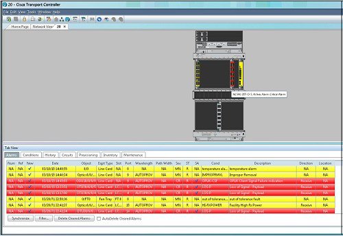
Configure the OTN
Cards
This chapter provides the CTC procedures to configure the OTN controllers. For more information on the OTN cards, see the data sheet
Datasheet link is http://www.cisco.com/c/en/us/products/collateral/optical-networking/network-convergence-system-4000-series/data_sheet_c78-729398.html
- Understand ODU and ODU Cross Connections
- NTP-K1 Configure the OTN Controllers Using CTC
- Upgrade to 400G Fabric Card Using CTC
- Upgrade FPD
Understand ODU and ODU Cross Connections
In the case of channelization, ODU is created as a sub controller of an OTU controller.
Optical Channel Data Unit (ODU ) contains information for maintenance and operational functions to support optical channels. ODU Over Head (OH) information is added to the ODU payload to create the complete ODUk. The ODUk OH consists of portions dedicated to the end-to-end ODUk path and to six levels of tandem connection monitoring. The ODUk path OH is terminated where the ODUk is assembled and disassembled. The TCM OH is added and terminated at the source and sink to the corresponding tandem connections.
ODU cross connection is an end-to-end channel between two OTN/Client ports in OTN network within NCS4k node.
NTP-K1 Configure the OTN Controllers Using CTC
| Purpose |
This procedure helps to configure the OTN controller that needs to create an OTN circuit . |
| Tools/Equipment | None |
| Prerequisite Procedures | None |
| Required/As Needed | As needed |
| Onsite/Remote | Onsite or remote |
| Security Level | Provisioning or higher |
End of procedure. |
DLP-K1 Configure an OTN Controller Using CTC
| Purpose | This procedure provides instructions to configure the OTN controller that helps to create an OTN circuit using CTC. |
| Tools/Equipment | None |
| Prerequisite Procedures | Login to CTC in System Setup and Software Installation Guide for Cisco NCS 4000 Series |
| Required/As Needed | As needed |
| Onsite/Remote | Onsite or remote |
| Security Level | Provisioning or higher |
DLP-K2 Configure an OTUk Controller Using CTC
| Purpose | This procedure provides instructions to configure the OTUk controller that helps to create an OTN circuit using CTC. |
| Tools/Equipment | None |
| Prerequisite Procedures | Login to CTC in System Setup and Software Installation Guide for Cisco NCS 4000 Series |
| Required/As Needed | As needed |
| Onsite/Remote | Onsite or remote |
| Security Level | Provisioning or higher |
DLP-K3 Configure an ODUk Controller Using CTC
| Purpose | This procedure provides instructions to configure an ODUk controller that helps to create an OTN circuit using CTC. |
| Tools/Equipment | None |
| Prerequisite Procedures | Login to CTC in System Setup and Software Installation Guide for Cisco NCS 4000 Series |
| Required/As Needed | As needed |
| Onsite/Remote | Onsite or remote |
| Security Level | Provisioning or higher |
DLP-K4 Configure the Section Trace for OTN Controllers Using CTC
| Purpose | This procedure provides instructions to configure the section trace that helps to create OTN circuit using CTC. |
| Tools/Equipment | None |
| Prerequisite Procedures | Login to CTC in System Setup and Software Installation Guide for Cisco NCS 4000 Series |
| Required/As Needed | As needed |
| Onsite/Remote | Onsite or remote |
| Security Level | Provisioning or higher |
DLP-K5 Configure the Alarm Threshold Values of OTN Controllers Using CTC
| Purpose | This procedure provides instructions to configure the threshold values of OTN controllers that helps to create OTN circuit using CTC. |
| Tools/Equipment | None |
| Prerequisite Procedures | Login to CTC in System Setup and Software Installation Guide for Cisco NCS 4000 Series |
| Required/As Needed | As needed |
| Onsite/Remote | Onsite or remote |
| Security Level | Provisioning or higher |
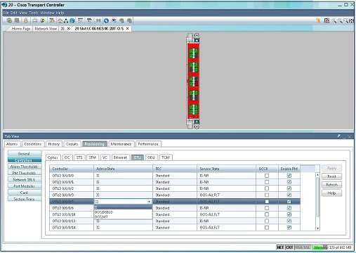
DLP-K6 Configure the Network SRLG for OTUk/Optics Controller Using CTC
| Purpose | This procedure provides instructions to configure the Shared Resource Link Group (SRLG) that helps to create an OTN circuit using CTC. |
| Tools/Equipment | None |
| Prerequisite Procedures | Login to CTC in System Setup and Software Installation Guide for Cisco NCS 4000 Series |
| Required/As Needed | As needed |
| Onsite/Remote | Onsite or remote |
| Security Level | Provisioning or higher |
| Step 1 | In the Node view, double-click the line card (NCS4K-20T-O-S/ NCS4K-2H-O-K/ NCS4K-24LR-O-S) to configure the network SRLG. |
| Step 2 | Click the Network SRLG > Network SRLG tab. |
| Step 3 | To configure network SRLG, click the Optics tab and perform the following steps in the screen that appears: |
| Step 4 | To configure network SRLG, click the OTU tab and perform the following steps: |
| Step 5 | Return to your originating procedure (NTP). |
DLP-K7 Connect Backplane/Regeneration of line cards Using CTC
| Purpose | This procedure provides instructions of connecting Backplane/Regeneration of line cards that helps to create an OTN circuit using CTC. |
| Tools/Equipment | None |
| Prerequisite Procedures | Login to CTC in System Setup and Software Installation Guide for Cisco NCS 4000 Series |
| Required/As Needed | As needed |
| Onsite/Remote | Onsite or remote |
| Security Level | Provisioning or higher |
| Step 1 | In the Node view, double-click the line card (NCS4K-20T-O-S/ NCS4K-2H-O-K/ NCS4K-24LR-O-S) to connect the backplane/regeneration. | ||
| Step 2 | Click the Provisioning > Card tab. | ||
| Step 3 | Click the
Backplane radio buttons and perform the following
steps in the screen that appears:
| ||
| Step 4 | Click the
Regeneration radio button and perform the following
steps in the screen that appears:
| ||
| Step 5 | Return to your originating procedure (NTP). |
DLP-K8 Create a Permanent Connection Using CTC
| Permanent connection allows to create a cross-connection. This procedure provides instructions to create a permanent connection using CTC. | |
| None | |
| Login to CTC in System Setup and Software Installation Guide for Cisco NCS 4000 Series | |
| As needed | |
| Onsite or remote | |
| Provisioning or higher |
| Step 1 | In the Node/Card View, double-click the line card (NCS4K-20T-O-S/ NCS4K-2H-O-K/ NCS4K-24LR-O-S) to create a permanent connection. | ||
| Step 2 | Click the Circuits > Permanent Connection tab. | ||
| Step 3 | Click
Create. Perform the following steps in the Create
Permanent Connection dialog box that appears.
| ||
| Step 4 | Return to your originating procedure (NTP). |
Upgrade to 400G Fabric Card Using CTC
| Purpose | This procedure provides instructions for upgrading from a 200G FC (NCS4016-FC-M) to a 400G FC (NCS4016-FC2-M). |
| Tools/Equipment | None |
| Prerequisite Procedures | Login to CTC in System Setup and Software Installation Guide for Cisco NCS 4000 Series |
| Required/As Needed | As needed |
| Onsite/Remote | Onsite or remote |
| Security Level | Provisioning or higher |
| Step 1 | In Node View , select the Maintenance tab. | ||||||||||||||
| Step 2 | Click
Fabric
Upgrade
to get the current Fabric Details. The table displays the
following details:
| ||||||||||||||
| Step 3 | Click Refresh Fabric Details Table , to get the updated table. | ||||||||||||||
| Step 4 | The Upgrade Wizard, provides the console for upgrading the fabric. Select the fabric plane from the Available Fabrics drop-down menu. Once this selection is done, the Available Fabrics option is grayed-out until the whole upgrade process is complete. | ||||||||||||||
| Step 5 | Click Next (referred to as Step-1 in the Upgrade Wizard) to shutdown the selected fabric plane; click Yes on the Confirmation Dialog. A message is displayed to indicate that the selected plane was successfully shutdown. | ||||||||||||||
| Step 6 | Click Next (refered to as Step-2) to shutdown the corresponding fabric card. | ||||||||||||||
| Step 7 | Replace the 200G
FC with a 400G FC and click
Next (referred to as Step 3 in the Upgrade Wizard).
The Revert option appears after Step-1. It allows the user to undo the action performed in the previous step. Be careful not to use this option after replacing the card. Clicking Revert will unshut the newly inserted card. | ||||||||||||||
| Step 8 | Wait for the Hardware Status column of the relevant Plane ID, in the fabric details table to display IS-NR, indicating in-service. Click Next (referred to as Step 4 in the Upgrade Wizard). | ||||||||||||||
| Step 9 | Click Next to upgrade the FPD device for the selected fabric (referred tp as Step 5 in the Upgrade Wizard). | ||||||||||||||
| Step 10 | On choosing to
upgrade the FPD device, a message is displayed recommending the user to check
the FPD status under the
Maintenance >
Software
>
FPD
Upgrade
tab.
The user has an option to click Skip to proceed without upgrading the FPD devices. The user can revisit the FPD Upgrade tab anytime to upgrade the FPDs. | ||||||||||||||
| Step 11 | Click Finish, to activate (no shutdown) the fabric plane (referred to as Step 6 in the Upgrade Wizard). The Available Fabrics drop-down menu is now available, wherein the user can select another fabric card. | ||||||||||||||
| Step 12 | The Output Window , displays the details of the performed actions. The user can extract this log by clicking the Export Log button and saving the information to a desired location. |
What to Do Next
Repeat the procedure to upgrade all the 200G FCs to 400G FCs. Mixed mode (where 200G FCs and 400G FCs co-exist) is recommended only while performing the upgrade . The user is required to upgrade all the FCs to 400G before making any configuration change(s).
Upgrade FPD
| Purpose |
This procedure helps to upgrade FPD image . |
| Tools/Equipment | None |
| Prerequisite Procedures | None |
| Required/As Needed | As needed |
| Onsite/Remote | Onsite or remote |
| Security Level | Provisioning or higher |
 Feedback