- Preface
-
- Configure Authentication
- Configure the NCS4K-2H-W Card
- Configure LC Priority Shutdown
- Configure AINS
- Configure Line Cards Using CTC
- Configure Circuits
- Configure the Bridge and Roll
- Configure Performance Monitoring
- Smart Licensing
- Manage Alarm Profiles
- Configure High Availability
- Configuring PRBS
- Configuring Breakout
- Manage the Node
- Configure SNMP
- Upgrade a Fabric Card
- Cable Management Utility
- Configure Affinity for OTN using CTC
- Migration : NCS4K-ECU to NCS4K-ECU2
- 24 Low Rate (LR) Datapath
- Configure Link Layer Discovery Protocol Using CTC
-
- Configure Authentication
- Configure Access Control Lists
- Configure LC Priority Shutdown
- Configure Controllers
- Configure the OTN Circuits
- Configure the OTN Protection
- Configure SNMP
- Configure Performance Monitoring
- Configure Fault Management
- Configuring PRBS
- Configuring Breakout
- Configure High Availability1
- Configure Layer 3 VPNs
- Configure Flex LSP
- Configure ISIS
- Bidirectional Forwarding Detection
- OSPF-IPv4
- Configure Ethernet OAM
- Configure Ethernet Service Activation Test
- Ethernet Local Management Interface
- MPLS Traffic Engineering
- Configure Frequency Synchronization
- Configuring Point to Point Layer 2 Services
- VLAN over ODU
- BGP Route Reflect
- Configure Smart Licensing
- Configure Link Aggregation
- Configure Link Layer Discovery Protocol
- Configure Affinity for OTN
- System Upgrade
- Capture Logs
- Inter-Rack RP Pairing
- Inter-rack Timing
- Configure Ethernet Data Plane Loopback
- Configure Zero Touch Provisioning
- Implement LPTS
- System Messages
- Administrative and Service States
- Understand SNMP
- Basic SNMP Components
- SNMPv3 Support
- SNMP Traps
- NTP-K8 Configure SNMP Using CTC
- DLP-G498 Create Group Access Using CTC
- DLP-G496 Creating an SNMPv3 User Using CTC
- DLP-G497 Create MIB Views Using CTC
- DLP-G499 Configure SNMPv3 Trap Destination Using CTC
- DLP-K88 Create SNMP Community Using CTC
- DLP-K89 Enabling SNMP Trap Notifications Using CTC
- DLP-G502 Manually Configuring the SNMPv3 Proxy Forwarder Table
- DLP-G503 Automatically Configuring the SNMPv3 Proxy Forwarder Table
- DLP-G505 Automatically Configuring the SNMPv3 Proxy Trap Forwarder Table
Configure
SNMP
This chapter explains Simple Network Management Protocol (SNMP) as implemented by Cisco NCS 4000 series.
- Understand SNMP
- Basic SNMP Components
- SNMPv3 Support
- SNMP Traps
- NTP-K8 Configure SNMP Using CTC
- DLP-G498 Create Group Access Using CTC
- DLP-G496 Creating an SNMPv3 User Using CTC
- DLP-G497 Create MIB Views Using CTC
- DLP-G499 Configure SNMPv3 Trap Destination Using CTC
- DLP-K88 Create SNMP Community Using CTC
- DLP-K89 Enabling SNMP Trap Notifications Using CTC
- DLP-G502 Manually Configuring the SNMPv3 Proxy Forwarder Table
- DLP-G503 Automatically Configuring the SNMPv3 Proxy Forwarder Table
- DLP-G505 Automatically Configuring the SNMPv3 Proxy Trap Forwarder Table
Understand SNMP
SNMP is an application-layer communication protocol that allows Cisco NCS 4000 series network devices to exchange management information among these systems and with other devices outside the network. Through SNMP, network administrators can manage network performance, find and solve network problems, and plan network growth.
NCS 4000 uses SNMP for asynchronous event notification to a network management system (NMS). SNMP implementation uses standard Internet Engineering Task Force (IETF) management information bases (MIBs) to convey node-level inventory, fault, and performance management information.
NCS 4000 supports SNMP Version 1 (SNMPv1), SNMP Version 2 (SNMPv2), and SNMP Version 3 (SNMPv3). As compared to SNMPv1, SNMPv2 includes additional protocol operations and 64-bit performance monitoring support. SNMPv3 provides authentication, encryption, and message integrity and is more secure.
Basic SNMP Components
In general terms, an SNMP-managed network consists of a management system, agents, and managed devices.
A management system executes monitoring applications and controls managed devices. Management systems execute most of the management processes and provide the bulk of memory resources used for network management. A network might be managed by one or several management systems. The following figure illustrates the relationship between the network manager, the SNMP agent, and the managed devices.
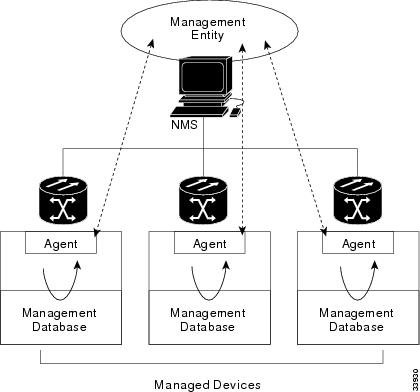
An agent (such as SNMP) residing on each managed device translates local management information data—such as performance information or event and error information—caught in software traps, into a readable form for the management system. The following figure illustrates SNMP agent get-requests that transport data to the network management software.
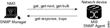
The SNMP agent captures data from MIBs, which are device parameter and network data repositories, or from error or change traps.
A managed element—such as a router, access server, switch, bridge, hub, computer host, or network element (such as an ONS 15454 NCSNCS 4000)—is accessed through the SNMP agent. Managed devices collect and store management information, making it available through SNMP to other management systems having the same protocol compatibility.
SNMPv3 Support
Cisco ONS 15454 NCS Software R9.0 and later supports SNMPv3 in addition to SNMPv1 and SNMPv2c. SNMPv3 is an interoperable standards-based protocol for network management. SNMPv3 provides secure access to devices by a combination of authentication and encryption packets over the network based on the User Based Security Model (USM) and the View-Based Access Control Model (VACM).
Cisco NCS 4000 supports SNMPv1, SNMPv2, and SNMPv3. SNMPv3 is an interoperable standards-based protocol for network management. SNMPv3 provides secure access to devices by a combination of authentication and encryption packets over the network based on the User Based Security Model (USM) and the View-Based Access Control Model (VACM).
-
User-Based Security Model—The User-Based Security Model (USM) uses the HMAC algorithm for generating keys for authentication and privacy. SNMPv3 authenticates data based on its origin, and ensures that the data is received intact. SNMPv1 and v2 authenticate data based on the plain text community string, which is less secure when compared to the user-based authentication model.
-
View-Based Access Control Model—The view-based access control model controls the access to the managed objects. RFC 3415 defines the following five elements that VACM comprises:
-
Groups—A set of users on whose behalf the MIB objects can be accessed. Each user belongs to a group. The group defines the access policy, notifications that users can receive, and the security model and security level for the users.
-
Security level—The access rights of a group depend on the security level of the request.
-
Contexts—Define a named subset of the object instances in the MIB. MIB objects are grouped into collections with different access policies based on the MIB contexts.
-
MIB views—Define a set of managed objects as subtrees and families. A view is a collection or family of subtrees. Each subtree is included or excluded from the view.
-
Access policy—Access is determined by the identity of the user, security level, security model, context, and the type of access (read/write). The access policy defines what SNMP objects can be accessed for reading, writing, and creating.
Access to information can be restricted based on these elements. Each view is created with different access control details. An operation is permitted or denied based on the access control details.
You can configure SNMPv3 on a node to allow SNMP get and set access to management information and configure a node to send SNMPv3 traps to trap destinations in a secure way. SNMPv3 can be configured in secure mode, non-secure mode, or disabled mode.
SNMP, when configured in secure mode, only allows SNMPv3 messages that have the authPriv security level. SNMP messages without authentication or privacy enabled are not allowed. When SNMP is configured in non-secure mode, it allows SNMPv1, SNMPv2, and SNMPv3 message types.
-
SNMP Traps
The ONS 15454 NCSNCS 4000 uses SNMP traps to generate all alarms and events, such as raises and clears. The traps contain the following information:
NTP-K8 Configure SNMP Using CTC
DLP-G498 Create Group Access Using CTC
|
This procedure creates a user group and configures the access parameters for the users in the group. |
|
DLP-G496 Creating an SNMPv3 User Using CTC
| Step 1 | In node view, click the tabs. |
| Step 2 | Click Create. |
| Step 3 | In the Create User dialog
box, enter the following information:
|
| Step 4 | Click OK to create an SNMP user. |
| Step 5 | Return to your originating procedure (NTP). |
DLP-G497 Create MIB Views Using CTC
| Step 1 | In node view, click the tabs. |
| Step 2 | Click Create. |
| Step 3 | In the Create Views dialog
box, enter the following information:
|
| Step 4 | Click OK to save the information. |
| Step 5 | Return to your originating procedure (NTP). |
DLP-G499 Configure SNMPv3 Trap Destination Using CTC
| Step 1 | In node view, click the tabs. |
| Step 2 | Click Create. |
| Step 3 | In the Configure SNMPv3 Trap
dialog box, enter the following information:
|
| Step 4 | In the Create SNMP Trap dialog box, enter the IP address of your network management system (NMS). |
| Step 5 | Click OK to save the information. |
| Step 6 | Return to your originating procedure (NTP). |
DLP-K88 Create SNMP Community Using CTC
| Step 1 | In node view, click the tabs. |
| Step 2 | In the Communities area,
click
Create.
The Create SNMP Community dialog box appears. |
| Step 3 | In the Destination area, the Destination Address field displays the trap destination address configured in DLP-G499 Configure SNMPv3 Trap Destination Using CTC. |
| Step 4 | Enter the User
Datagram Protocol (UDP) port on which you want to create a community in the UDP
Port field.
The default UDP port for SNMP is 162. |
| Step 5 | In the User
area, choose the user from the User Name droop-down list.
The SNMP version and the security level of the selected user are displayed. |
| Step 6 | In the Notification area, check the required basic trap types. The available options are BGP, Config, Syslog, and SNMP. |
| Step 7 | From the Advance Trap Types drop-down list, choose None or Copy Complete. |
| Step 8 | Click OK to create SNMP community. |
| Step 9 | Return to your originating procedure (NTP). |
DLP-K89 Enabling SNMP Trap Notifications Using CTC
|
This procedure enables SNMP trap notifications that are sent to a MIB tree. |
|
|
"Login to CTC" in System Setup and Software Installation Guide for Cisco NCS 4000 Series |
|
DLP-G502 Manually Configuring the SNMPv3 Proxy Forwarder Table
|
This procedure creates an entry in the SNMPv3 Proxy Forwarder Table. |
|
| Step 1 | In network view, click . |
| Step 2 | In the SNMPv3 Proxy Server area, complete the following: |
| Step 3 | In the SNMPv3 Proxy Forwarder Table area, click Manual Create. |
| Step 4 | In the Manual
Configuration of SNMPv3 Proxy Forwarder dialog box, enter the following
information:
|
| Step 5 | Click OK to save the information. |
| Step 6 | Return to your originating procedure (NTP). |
DLP-G503 Automatically Configuring the SNMPv3 Proxy Forwarder Table
|
This procedure creates an entry in the SNMPv3 Proxy Forwarder Table. |
|
| Step 1 | In network view, click tabs. | ||
| Step 2 | In the SNMPv3 Proxy Server area, complete the following: | ||
| Step 3 | In the SNMPv3 Proxy Forwarder Table area, click Auto Create. | ||
| Step 4 | In the Automatic
Configuration of SNMPv3 Proxy Forwarder dialog box, enter the following
information:
| ||
| Step 5 | Click OK to save the settings. | ||
| Step 6 | Return to your originating procedure (NTP). |
DLP-G505 Automatically Configuring the SNMPv3 Proxy Trap Forwarder Table
|
This procedure creates an entry in the SNMPv3 Proxy Trap Forwarder Table automatically. |
|
| Step 1 | In network view, click tabs. |
| Step 2 | In the SNMPv3 Proxy Server area, complete the following: |
| Step 3 | In the SNMPv3 Proxy Trap Forwarder Table area, click Auto Create. |
| Step 4 | In the Automatic
Configuration of SNMPv3 Proxy Trap Forwarder dialog box, enter the following
information:
|
| Step 5 | Click OK to save the information. |
| Step 6 | Return to your originating procedure (NTP). |
 Feedback