- Preface
-
- Configure Authentication
- Configure the NCS4K-2H-W Card
- Configure LC Priority Shutdown
- Configure AINS
- Configure Line Cards Using CTC
- Configure Circuits
- Configure the Bridge and Roll
- Configure Performance Monitoring
- Smart Licensing
- Manage Alarm Profiles
- Configure High Availability
- Configuring PRBS
- Configuring Breakout
- Manage the Node
- Configure SNMP
- Upgrade a Fabric Card
- Cable Management Utility
- Configure Affinity for OTN using CTC
- Migration : NCS4K-ECU to NCS4K-ECU2
- 24 Low Rate (LR) Datapath
- Configure Link Layer Discovery Protocol Using CTC
-
- Configure Authentication
- Configure Access Control Lists
- Configure LC Priority Shutdown
- Configure Controllers
- Configure the OTN Circuits
- Configure the OTN Protection
- Configure SNMP
- Configure Performance Monitoring
- Configure Fault Management
- Configuring PRBS
- Configuring Breakout
- Configure High Availability1
- Configure Layer 3 VPNs
- Configure Flex LSP
- Configure ISIS
- Bidirectional Forwarding Detection
- OSPF-IPv4
- Configure Ethernet OAM
- Configure Ethernet Service Activation Test
- Ethernet Local Management Interface
- MPLS Traffic Engineering
- Configure Frequency Synchronization
- Configuring Point to Point Layer 2 Services
- VLAN over ODU
- BGP Route Reflect
- Configure Smart Licensing
- Configure Link Aggregation
- Configure Link Layer Discovery Protocol
- Configure Affinity for OTN
- System Upgrade
- Capture Logs
- Inter-Rack RP Pairing
- Inter-rack Timing
- Configure Ethernet Data Plane Loopback
- Configure Zero Touch Provisioning
- Implement LPTS
- System Messages
- Administrative and Service States
- NTP-K7 Manage the Node Using CTC
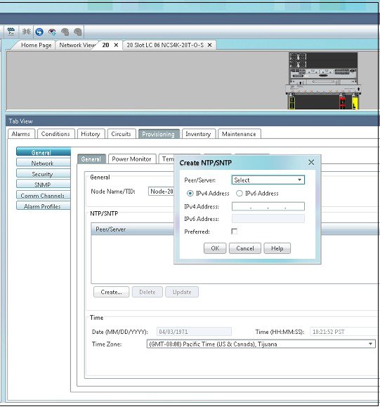
- DLP-K59 Set Up Name, Date, and Time Information Using CTC
- DLP-K84 Back Up the Configuration Using CTC
- DLP-K85 Restore the Configuration Using CTC
- DLP-K86 View and Archive the Audit Trail Records Using CTC
- DLP-K64 Monitor Environmental Parameters Using CTC
- Equipment Inventory
- DLP-K87 Reset Cards Using CTC
- Firewall Ports
Manage the
Node
This chapter provides the CTC procedures for maintaining the nodes, including backup and restoration, viewing the audit trails, and resetting the cards.
- NTP-K7 Manage the Node Using CTC
- DLP-K59 Set Up Name, Date, and Time Information Using CTC
- DLP-K84 Back Up the Configuration Using CTC
- DLP-K85 Restore the Configuration Using CTC
- DLP-K86 View and Archive the Audit Trail Records Using CTC
- DLP-K64 Monitor Environmental Parameters Using CTC
- Equipment Inventory
- DLP-K87 Reset Cards Using CTC
- Firewall Ports
NTP-K7 Manage the Node Using CTC
| Login to CTC in System Setup and Software Installation Guide for Cisco NCS 4000 Series | |
DLP-K59 Set Up Name, Date, and Time Information Using CTC
DLP-K84 Back Up the Configuration Using CTC
|
Purpose |
This procedure stores a backup version of the Cisco NCS 4000 node configuration on the workstation running CTC or on a network server. |
|
Tools/Equipment |
None |
|
Prerequisite Procedures |
Login to CTC in System Setup and Software Installation Guide for Cisco NCS 4000 Series |
|
Required/As Needed |
Required. Cisco recommends performing a configuration backup at approximately weekly intervals and prior to and after configuration changes. |
|
Onsite/Remote |
Onsite or remote |
|
Security Level |
Maintenance or higher |
DLP-K85 Restore the Configuration Using CTC
|
Purpose |
This procedure restores the NCS 4000 configuration from the configuration file on the workstation running CTC or on a network server. |
|
Tools/Equipment |
None |
|
Prerequisite Procedures |
|
|
Required/As Needed |
As needed |
|
Onsite/Remote |
Onsite or remote |
|
Security Level |
Maintenance or higher |
DLP-K86 View and Archive the Audit Trail Records Using CTC
|
Purpose |
This procedure explains how to view and archive audit trail records. |
|
Tools/Equipment |
None |
|
Prerequisite Procedures |
Login to CTC in System Setup and Software Installation Guide for Cisco NCS 4000 Series |
|
Required/As Needed |
As needed |
|
Onsite/Remote |
Onsite or remote |
|
Security Level |
Provisioning or higher |
In NCS 4000, audit trail is used to view the list of all the configuration commands issued to the node. Audit trail records are useful for maintaining security, recovering lost transactions, and enforcing accountability. Accountability refers to tracing user activities; that is, associating a process or action with a specific user.
You need to archive the audit trail logs to maintain a record of actions performed for the node. If the audit trail log is not archived, the oldest entries are overwritten after the log reaches capacity.
DLP-K64 Monitor Environmental Parameters Using CTC
|
This procedure monitors the environmental parameters of the Cisco NCS 4000 chassis. |
|
| Login to CTC in System Setup and Software Installation Guide for Cisco NCS 4000 Series | |
| Step 1 | In the Node View, click the tabs. |
| Step 2 | Click the
sub-tab.
This sub-tab dynamically displays the power consumption values of the NCS 4000 chassis. The values are displayed based on the input voltage going into the system.
|
| Step 3 | Click the
sub-tab.
This sub-tab displays the input temperature of the NCS 4000 chassis.
|
| Step 4 | Click the
sub-tab.
This sub-tab displays the input voltage of the NCS 4000 chassis. |
| Step 5 | Click the
sub-tab.
This sub-tab displays the input values of fan speed supply in the NCS 4000 chassis. The values are displayed based on the input speed going into the fan. |
| Step 6 | Return to your originating procedure (NTP). |
Equipment Inventory
In node view, the Inventory tab displays information about the NCS 4000 equipment, including:
-
Location—Identifies where the equipment is installed, either chassis or slot number.
-
Eqpt Type—Displays the type of equipment.
-
Admin State—Changes the service state of the card unless network conditions prevent the change.
The administrative state changes to OOS,DSBLD when the card is shut down due to insufficient power.
-
Service State—Displays the current card service state, which is an autonomously generated state that gives the overall condition of the card. Service states appear in the format: Primary State-Primary State Qualifier, Secondary State.
-
Description—Displays the description of the equipment.
-
HW Part #—Displays the hardware part number; this number is printed on top of the card.
-
Replaceable—Indicates whether an equipment can be replaced or not.
-
Serial #—Displays the equipment serial number; this number is unique to each card.
-
Uptime—Displays the time from the last boot.
-
PCA#—
-
Product ID—Displays the manufacturing product identifier for a hardware component, such as a fan tray, chassis, or card.
-
Version ID—Displays the manufacturing version identifier for a fan tray, chassis, or card.
-
CLEI—Displays the Common Language Equipment Identifier code.
-
HW ID—Displays the hardware identifier of the equipment.
DLP-K87 Reset Cards Using CTC
|
Purpose |
This procedure resets the cards using CTC. |
|
Tools/Equipment |
None |
|
Prerequisite Procedures |
"Login to CTC" in System Setup and Software Installation Guide for Cisco NCS 4000 Series |
|
Required/As Needed |
As needed |
|
Onsite/Remote |
Onsite or remote |
|
Security Level |
Superuser only |
Only the hard reset of the card is supported. The hard reset temporarily removes power from the card and clears all the buffer memory.
| Step 1 | In node view, click the Inventory tab. |
| Step 2 | Choose a card and click Hard-Reset Card to initiate a hard reset. |
| Step 3 | Click Yes when the confirmation dialog box appears. |
| Step 4 | (Only for Route Processor cards) Click Close when the “Lost connection to node, changing to Network View” dialog box appears. |
| Step 5 | Return to your originating procedure (NTP). |
Firewall Ports
The following table lists the ports that must be enabled to establish a communication channel with the NE (controller card).
|
SSH |
SSH port on NE |
Secure |
22 |
Inbound |
|
Telnet |
Telnet port on NE |
Standard |
23 |
Inbound |
|
162 (default); user configurable to any port between 1024 to 65535 |
||||
 Feedback