Serial MPLS Pseudowire

Serial MPLS pseudowire on IR8340

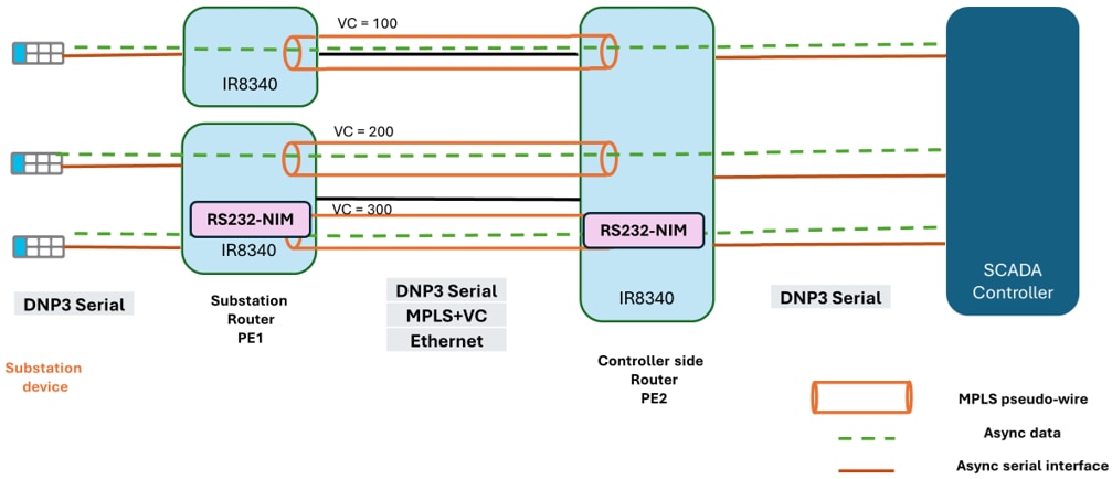
From IOS XE Release 17.17.1, you can transfer the serial async data using an MPLS label over a pseudowire between two IR8340 edge routers. In this scenario, one of the routers is located at the substation end and the other router is located at the controller end. Serial PW feature is configurable through CLI, Netconf/Yang and SDWAN/Vmanage interfaces. Oper Netconf/Yang model for this feature is not supported in 17.17.1 IOS-XE Release.

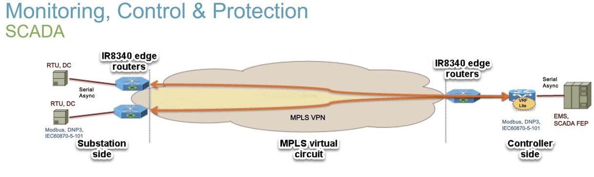
Following are the key networking elements in this scenario:

  • Substation: This refers to a location within an IIoT utility setup where edge routers are present, typically involved in collecting data from Remote Terminal Units (RTUs).

  • Controller: This is the location where the controller edge router is deployed, which receives the MPLS-encapsulated data from the substation.

  • Substation RTUs: These are responsible for collecting and transmitting data from various sensors and devices located at the substation. Substation RTU interfaces with an IR8340 edge router to enable data transfer to the controller and these are located at the substation side. One IR8340 router is installed at the end of each substation RTU.

  • SCADA controller: This is located at the controller side. One IR8340 router is installed at the end of the SCADA controller.

  • MPLS virtual circuit (VC): It is created between the two edge routers using MPLS LDP signaling protocol.

For more information about MPLS forwarding and raw socket configuration, refer the configuration guidelines reference links MPLS Pseudowire Status Signaling and Raw Socket Transport.

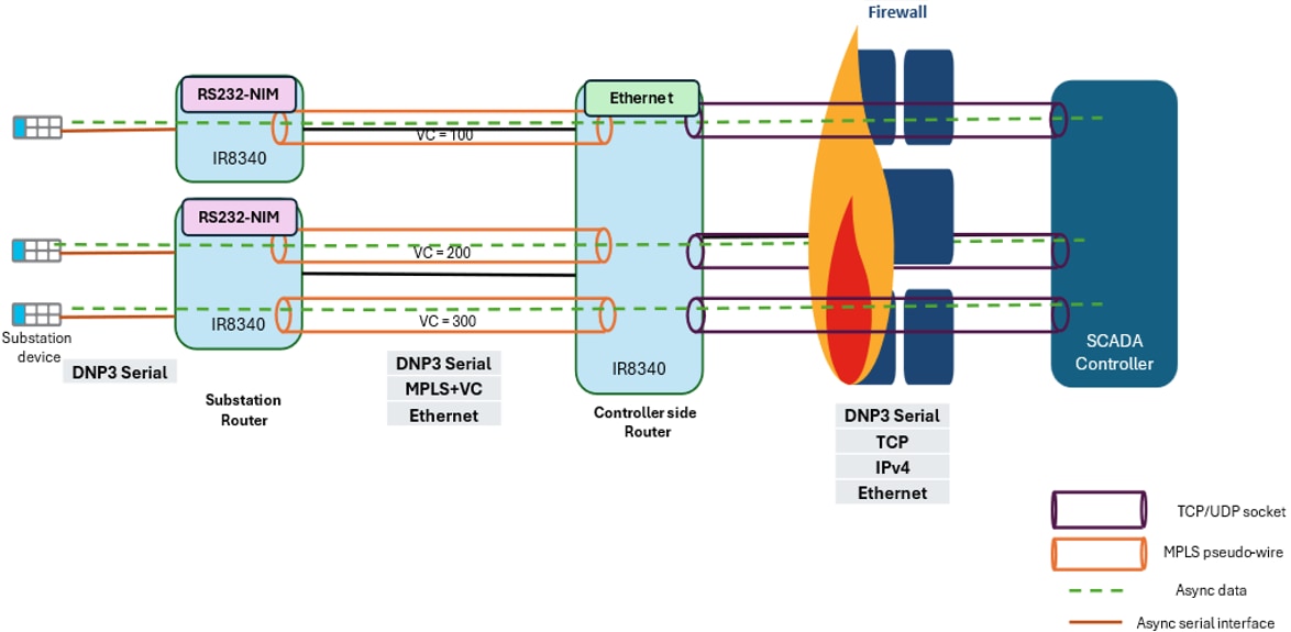
Serial MPLS pseudowire for compliance and cost efficiency data transfer

Async serial data is exchanged between substation RTUs and a remote SCADA management station through a public IP network. However, due to compliance with regulatory requirements, you must perform a firewall inspection for TCP/IP packets at the substation RTUs before data enters the cloud. In this scenario, customers have large numbers of substation plants and few remote SCADA servers. Using existing IP-based data transfer, user must install firewalls at all substation plant locations, thereby increasing investment for data transfer.

In the above async serial data exchange scenario, you can control data transfer costs by skipping the TCP/IP headers and sending the data in the MPLS pseudowire format. This approach reduces the cost by eliminating the need for firewall inspections at the substation RTUs. After you decapsulate the data at the controller edge router, add the TCP/IP headers and the IP address of the remote SCADA server. Then, forward this data through the IP network and the firewall over an established raw socket session.

Data exchange between substation RTU and SCADA controller using MPLS pseudowire

Data is exchanged between the substation and the controller’s edge routers using a serial MPLS pseudowire.

Data transfer from substation RTU to SCADA controller

DNP3 or SCADA serial data received at the substation router is encapsulated with an MPLS label and transferred over a pseudowire towards the controller's edge router. An MPLS VC is created between the two edge routers with an RS232 async serial interface as the Attachment Circuit (AC) on the substation router and loopback as an AC on the controller router. The substation router labels each async payload with a configured VC identifier. This allows the controller-side router to map the incoming serial packet to the correct VC and forward it to the right SCADA controller IP address. After receiving the data from the substation edge router, the controller edge router performs these tasks:

  • Decapsulates the MPLS-encapsulated async serial packets to retrieve the original async serial data.

  • Adds TCP/IP headers for the remote SCADA server and send the data through an established raw socket session over the IP network and firewall.

Data transfer from SCADA controller to substation RTU

When data is received from a remote SCADA, the controller edge router removes TCP/IP headers and encapsulates the raw serial data into MPLS frames to send back to the substation router through an MPLS pseudowire.

Serial MPLS pseudowire deployment scenarios

Serial pseudowire feature supports following two deployment scenarios between the two IR8340 edge routers:

  • Serial to serial MPLS pseudowire deployment

  • Serial to raw socket (IP) MPLS pseudowire deployment

Serial to serial MPLS pseudowire deployment

A like-to-like MPLS virtual circuit is created between the two IR8340 edge routers with RS232 async serial interface as Attachment Circuit. In this scenario, both substation and controller-side edge routers have serial interface endpoints. In this deployment method, two IR8340 edge routers performs these tasks:

  • Transfers data using serial interfaces between the two edge routers.

  • Creates an MPLS VC between the two edge routers.

  • Encapsulates the data packet from the substation RTU into an MPLS label stack and transfer it to the controller's edge router.

  • Decapsulates the received data at the controller router and transfer the raw data towards the FEP controller.


Note


  • The controller's edge router transfers data to the substation's edge router in the same manner.

  • Both the encapsulation and decapsulation of data packet occurs at substation and controller edge routers.


Serial to raw socket (IP) MPLS pseudowire deployment

In this deployment, to transfer the data, the customer has an RS232 serial endpoint at substation edge router and raw socket virtual interface as terminating endpoint on the controller side router for end-to-end SCADA service. This necessitates serial to raw socket interworking between the two edge routers to interconnect two ACs. The Loopback interface is configured as an AC interface on the controller router to set up the serial to raw socket virtual circuit. In this scenario, the following data exchange happens between the serial to raw socket of IR8340 edge routers:

  • Transfers data using serial to raw socket between both edge routers.

  • Creates an MPLS VC between the two edge routers.

  • Encapsulates the data packet from the substation RTU into an MPLS label stack and transfer it to the controller's edge router.

  • Decapsulates the received data at the controller router and transfer the raw data towards the FEP controller.


Note


  • The controller's edge router transfers data to the substation's edge router in the same manner.

  • Both the encapsulation and decapsulation of data packet occurs at substation and controller edge routers.


Serial to serial MPLS pseudowire deployment configuration using CLI

Perform these tasks for serial to serial configuration between two edge routers to transfer the data.

Procedure


Step 1

Use the pseudowire-class PW-class-name command to create a pseudowire class.

device#pseudowire-class SERIAL_PW

Step 2

Use the encapsulation mpls command to facilitate the encapsulation and transfer of data over an MPLS network.

device#encapsulation mpls

Step 3

Use the status control-plane route-watch command to monitor the status of the control plane and to track route changes on the device.

device#status control-plane route-watch

Step 4

Use the switching tlv command to configure the TLV settings on the device.

device#switching tlv

Step 5

Use the interface Serial0/2/4 command to configure the specific serial interface on the device.

device#interface Serial0/2/4

Note

 
  • 0: refers to the chassis,

  • 2: represents the slot number within the chassis, and

  • 4: denotes the specific port or interface number on the module.

Step 6

Use the physical-layer async command to configure serial interface for async data transfer.

device#physical-layer async

Step 7

Use the xconnect IP address VC ID value encapsulation mpls pw-class SERIAL_PW command to configure the VC to a remote endpoint.

device(config-if)#xconnect 199.11.1.1 2000 e
device(config-if)#xconnect 199.11.1.1 2000 encapsulation m
device(config-if)#xconnect 199.11.1.1 2000 encapsulation mpls pw
device(config-if)#$000 encapsulation mpls pw-class SERIAL_TO_SERIAL
device(config-if-xconn)#

Note

 
  • You can configure a similar serial xconnect on the serial interface of the controller-side router.

  • Here xconnect IP address denotes the IP address of the remote endpoint. This command establishes a point-to-point connection over a pseudowire between the local and remote devices.

For more information about MPLS configuration guide, refer MPLS Pseudowire Status Signaling.


Serial to raw socket (IP) MPLS pseudowire deployment configuration using CLI

Perform these tasks for serial to raw socket (IP) configuration between two edge routers to transfer the data.

Before you begin


Note


First you must configure the raw socket on the loop back interface, before MPLS pseudowire VC is established.


Procedure


Step 1

Use the pseudowire-class PW-class-name command to create a pseudowire class.

device#pseudowire-class SERIAL_PW

Step 2

Use the encapsulation mpls command to facilitate the encapsulation and transfer of data over an MPLS network.

device#encapsulation mpls

Step 3

Use the interworking ethernet command to enable Ethernet interworking on a network device.

device#interworking ethernet

Note

 
  • Interworking Ethernet configuration is also required on the serial interface of the substation router.

  • As we have different types of ACs at both ends, interworking ethernet is required to make the VC functional.

Step 4

Use the status command to verify the current state of the device.

device#status

Step 5

Use the status control-plane route-watch command to monitor the status of the control plane and to track route changes on the device.

device#status control-plane route-watch

Step 6

Use the switching tlv command to configure the TLV settings on the device.

device#switching tlv

Step 7

Use the interface Loopback1 command to configure the loopback interface on the device.

device(config)#interface Loopback1

Note


1: Identifier for the specific loopback interface. This numbering helps distinguish between different loopback interfaces on a network device.

Step 8

Use the no ip address command is used to ensure that no IP address is assigned to the interface. If you don’t assign an IP address, the loopback interface is used solely as an AC for the VC in the MPLS network.

device#no ip address

Step 9

Use the mtu value command to configure the mtu value as 1514 bytes on the specified interface.

device (config)#
device (config)#int ser0/3/4
device (config-if)#mtu 1514
device (config-if)#

Note

 
  • Configuring the MTU default value as 1514 bytes ensures that the data packets are of the correct size for your network configuration. This prevents them from breaking up and improves performance.

  • MTU value should be same on both the serial interfaces of substation router and loopback interface on controller router.

Step 10

Use the xconnect IP address VC ID value encapsulation mpls pw-class SERIAL_PW command to configure the VC to a remote endpoint.

device(config-if)#xconnect 199.11.1.1 2000 e
device(config-if)#xconnect 199.11.1.1 2000 encapsulation m
device(config-if)#xconnect 199.11.1.1 2000 encapsulation mpls pw
device(config-if)#$000 encapsulation mpls pw-class SERIAL_TO_IP
device(config-if-xconn)#

Note


Here xconnect IP address denotes the IP address of the remote endpoint. This command establishes a point-to-point connection over a pseudowire between the local and remote devices.

For more methods of serial to raw socket configurations, refer chapter Raw Socket Transport.


Raw socket configuration using CLI

Use the Interface loopback value raw-socket tcp client server_ip server_port client_ip client_port command to configure a loopback interface with a raw TCP socket setup, where the interface acts as a TCP client connecting to a specified server IP and port.

device(config)#
device(config)#inter
device(config)#interface Loo
device(config)#interface Loopback 10
device(config-if)#raw
device(config-if)#raw-socket tcp cl
device(config-if)#raw-socket tcp client 6.6.6.1 5000 6.6.6.2 4000
device(config-if)#

Verify serial to serial configurations using CLI

Use the sh xconnect all command to verify the serial to serial configuration on the device.
Device#sh xconnect all
Legend:    XC ST=Xconnect State  S1=Segment1 State  S2=Segment2 State
  UP=Up       DN=Down            AD=Admin Down      IA=Inactive
  SB=Standby  HS=Hot Standby     RV=Recovering      NH=No Hardware

XC ST  Segment 1                         S1 Segment 2                         S2
------+---------------------------------+--+---------------------------------+--
UP pri   ac Se0/2/4(HDLC)                UP mpls 192.168.1.102:1000           UP
UP pri   ac Se0/2/5(HDLC)                UP mpls 192.168.1.102:2000           UP

verify serial interface configuration using CLI

Use the sh run int ser0/2/5 command to verify the serial interface configuration on the device.


Device#sh run int ser0/2/5
Building configuration...

Current configuration : 150 bytes
!
interface Serial0/2/5
 physical-layer async
 no ip address
 cdp enable
 xconnect 192.168.1.102 1000 encapsulation mpls pw-class SERIAL_PW_TEST
end

Verify serial to serial MPLS Layer2 transport using CLI

Use the sh mpls l2transport vc id detail command to verify layer2 vpn provisioned vc details on the device.

Device#sh mpls l2transport vc 1000 detail 
Local interface: Se0/2/5 up, line protocol up, HDLC up
  Destination address: 192.168.1.102, VC ID: 1000, VC status: up
    Output interface: Gi0/0/1, imposed label stack {19 20}
    Preferred path: not configured  
    Default path: active
    Next hop: 11.1.1.102
  Create time: 01:04:45, last status change time: 00:57:29
    Last label FSM state change time: 00:57:29
  Signaling protocol: LDP, peer 192.168.1.102:0 up
    Targeted Hello: 192.168.1.103(LDP Id) -> 192.168.1.102, LDP is UP
    Graceful restart: not configured and not enabled
    Non stop routing: not configured and not enabled
    Status TLV support (local/remote)   : enabled/supported
      LDP route watch                   : enabled
      Label/status state machine        : established, LruRru
      Last local dataplane   status rcvd: No fault
      Last BFD dataplane     status rcvd: Not sent
      Last BFD peer monitor  status rcvd: No fault
      Last local AC  circuit status rcvd: No fault
      Last local AC  circuit status sent: No fault
      Last local PW i/f circ status rcvd: No fault
      Last local LDP TLV     status sent: No fault
      Last remote LDP TLV    status rcvd: No fault
      Last remote LDP ADJ    status rcvd: No fault
    MPLS VC labels: local 19, remote 20 
    Group ID: local n/a, remote 0
    MTU: local 1500, remote 1500
    Remote interface description: 
  Sequencing: receive disabled, send disabled
  Control Word: On (configured: autosense)
  SSO Descriptor: 192.168.1.102/1000, local label: 19
  Dataplane:
    SSM segment/switch IDs: 8199/8195 (used), PWID: 1
  VC statistics:
    transit packet totals: receive 9, send 11
    transit byte totals:   receive 540, send 319
    transit packet drops:  receive 0, seq error 0, send 0

Verify the serial to serial data and operational statistics of the specified serial interface

Use the hardware subslot 0/2 module interface ser0/2/5 statistics command is to gather and display performance data and operational statistics for the specified serial interface on the device.
Device#$ hardware subslot 0/2 module interface ser0/2/5 statistics 

SCC driver stats
----------------
 Rx intr: 0 Tx intr: 11
 Rx frames: 0 Tx frames: 11
 Rx bytes: 0 Tx bytes: 11
 Rx host-if down drops: 0
 Rx Resource errors: 0
 Rx Unrecoverable errors: 0
 Tx unrecoverable errors: 0
 Tx chain errors: 0
 Tx underruns: 0
 Rx ring head: 11
 HP1 Tx ring head: 20  tail: 20
 HP2 Tx ring head: 0  tail: 0
 LP Tx ring head:  0  tail: 0
 Tx ring size: 1024  Rx ring size: 128

Tx Xmit Checks
--------------
 Tx skb null: 0
 Tx num ports not initialized: 0
 Tx invalid iid: 0
 Tx port disabled: 0
 Tx line down: 0
 Tx invalid qos priority: 0
 Tx dring full: 0
 Tx buf exceeds mtu: 0


Supported HQF Queues: HP1 HP2 LP

HQF stats port 5                 HP1                 HP2                  LP
----------------------------------------------------------------------------
       Throttles                   0                   0                   0
         Enables                   0                   0                   0
Throttle refresh                   0                   0                   0
  Enable refresh                   0                   0                   0
       Throttled                   0                   0                   0
      Tx Packets                  11                   0                   0
        Tx bytes                  11                   0                   0
        Tx Drops                   0                   0                   0
   Overflow drop                   0                   0                   0
   Tx Queue size                1024                1024                1024
      Max Qdepth                   0                   0                   0
      Cur Qdepth                   0                   0                   0

Verify Serial to raw socket (IP) configurations using CLI

Use the sh xconnect all command to verify the serial to raw socket configuration.
Device#sh xconnect all
Legend:    XC ST=Xconnect State  S1=Segment1 State  S2=Segment2 State
  UP=Up       DN=Down            AD=Admin Down      IA=Inactive
  SB=Standby  HS=Hot Standby     RV=Recovering      NH=No Hardware

XC ST  Segment 1                         S1 Segment 2                         S2
------+---------------------------------+--+---------------------------------+--
UP pri   ac Lo8(ASYNC)                   UP mpls 192.168.1.103:1000           UP

Verify serial to raw socket MPLS Layer2 transport using CLI

Use the sh mpls l2transport vc id detail command to verify serial to raw socket MPLS Layer2 vpn provisioned vc details.

Device#sh mpls l2transport vc 1000 detail 
Local interface: Lo8 up, line protocol up, ASYNC up
  Interworking type is Ethernet
  Destination address: 192.168.1.103, VC ID: 1000, VC status: up
    Output interface: Gi0/0/1, imposed label stack {16 16}
    Preferred path: not configured  
    Default path: active
    Next hop: 13.1.1.102
  Create time: 00:04:07, last status change time: 00:04:07
    Last label FSM state change time: 00:04:07
  Signaling protocol: LDP, peer 192.168.1.103:0 up
    Targeted Hello: 192.168.1.102(LDP Id) -> 192.168.1.103, LDP is UP
    Graceful restart: not configured and not enabled
    Non stop routing: not configured and not enabled
    Status TLV support (local/remote)   : enabled/supported
      LDP route watch                   : enabled
      Label/status state machine        : established, LruRru
      Last local dataplane   status rcvd: No fault
      Last BFD dataplane     status rcvd: Not sent
      Last BFD peer monitor  status rcvd: No fault
      Last local AC  circuit status rcvd: No fault
      Last local AC  circuit status sent: No fault
      Last local PW i/f circ status rcvd: No fault
      Last local LDP TLV     status sent: No fault
      Last remote LDP TLV    status rcvd: No fault
      Last remote LDP ADJ    status rcvd: No fault
    MPLS VC labels: local 21, remote 16 
    Group ID: local n/a, remote 0
    MTU: local 1514, remote 1514
    Remote interface description: 
  Sequencing: receive disabled, send disabled
  Control Word: On (configured: autosense)
  SSO Descriptor: 192.168.1.103/1000, local label: 21
  Dataplane:
    SSM segment/switch IDs: 4097/4096 (used), PWID: 1
  VC statistics:
    transit packet totals: receive 0, send 0
    transit byte totals:   receive 0, send 0
    transit packet drops:  receive 0, seq error 0, send 0

Verify serial to raw socket bindings between Layer 2 circuits and MPLS labels using AToM

Use the sh l2vpn atom binding command to verify bindings between Layer 2 circuits and MPLS labels within an L2VPN using AToM on the device.

Device#sh l2vpn atom binding 
  Destination Address: 192.168.1.103,VC ID: 1000
    Local Label:  21
        Cbit: 1,    VC Type: Ethernet,    GroupID: n/a
        MTU: 1514,   Interface Desc: n/a
        VCCV: CC Type: RA [2], TTL [3]
              CV Type: LSPV [2]
    Remote Label: 16
        Cbit: 1,    VC Type: Ethernet,    GroupID: 0
        MTU: 1514,   Interface Desc: n/a
        VCCV: CC Type: CW [1], RA [2], TTL [3]
              CV Type: LSPV [2]

Verify raw-socket tcp sessions

Use the sh raw-socket tcp sessions command to verify established tcp session with loopback AC and remote raw socket server on the device.

Device#sh raw-socket tcp sessions 
-------------------------------------------------- TCP Sessions ------------------------------------------------------
Interface   tty/(Idx)     vrf_name           socket   mode    local_ip_addr  local_port    dest_ip_addr  dest_port    up_time     idle_time/timeout
  Lo8       ( 35)                                0    client   55.0.0.2         4000          55.0.0.1       5000     00:00:29    00:00:29/300sec

Verify raw-socket tcp statistic

Use the sh raw-socket tcp statistic command to verify the raw socket transport tcp session packet statistics created between loopback based client and SCADA server over IP network on the device.

Device#sh raw-socket tcp statistic 
-------------------------------------------- TCP-Serial Statistics -----------------------------------------
Interface  idx             vrf_name             sessions      tcp_in_bytes         tcp_out_bytes   tcp_to_tty_frames    tty_to_tcp_frames
Lo8         35                                       1             0                    0                   0                    0
Se0/3/4     54                                       1             0                    0                   0                    0

Verify raw socket configuration using CLI

Use the sh raw-socket tcp sessions local | inc Lo10 command to verify the raw socket configuration on the device.

device#sh raw-socket tcp sessions local | inc Lo10
Lo10       48   6.6.6.1           5000     6.6.6.2           4000      DOWN

Limitations and restrictions of current serial MPLS pseudowire release

  • Current IOS XE Release 17.17.1 supports only RS232-NIM based serial to serial and Serial to IP use case scenarios. It does not support T1E1-NIM based deployment cases in this release.

  • This feature is supported only on the IR8340 and not on other IoT routing devices.

  • Serial and loopback AC ports support interface-based xconnect configuration but do not support L2VPN xconnect configuration.

  • For the serial to IP use case, only raw socket functionality is enabled for the loopback interface.

  • Current IOS XE Release 17.17.1 does not support the raw socket server and other packetization criteria such as packet length, timer, and special character. Data packets are exchanged between substation and controller.

  • The loopback does not support a raw socket using the UDP protocol.

  • In a multi-controller environment, user can configure up to 1000 raw socket TCP clients on a loopback interface to support high availability.

  • The serial PW feature on the controller router mainly supports SCADA aggregator functions for substation RTUs, using loopback as the PW endpoint and a raw socket client. Although having both serial and loopback-based raw sockets on the controller router is not typical for utility customers, this setup is supported for future needs. In this case, unique destination and source IP addresses and TCP port numbers are recommended to ensure proper functionality.

  • In a serial-IP deployment, the VC statistics show Rx counters as zero because the packets are sent to the raw socket IOS application for further TCP/IP processing.

  • You cannot configure the same raw socket TCP client on two loopbacks.

  • Enable the raw socket before configuring xconnect on a loopback.

  • You cannot configure both the VRF and xconnect on the same serial async interface.