
Managing Active Sessions
IoT FND tracks active user sessions and lets you log out users.
Viewing Active Sessions
To view active user sessions:
Procedure
|
Choose . 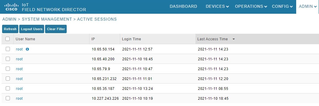
|
Logging Out Users
To log out an IoT FND user:
Procedure
|
Step 1 |
Choose . |
|
Step 2 |
Select the check boxes for those users you want to log out. |
|
Step 3 |
Click Logout Users. |
|
Step 4 |
Click Yes to confirm logout of the users. |
Filtering the Active Sessions List
To filter the Active Sessions list using column filtering:
Procedure
|
Step 1 |
Choose . |
||
|
Step 2 |
Hover the mouse over the User Name column heading to expose the filter icon (triangle). Enter the user name or the first characters of the user name to filter the list. 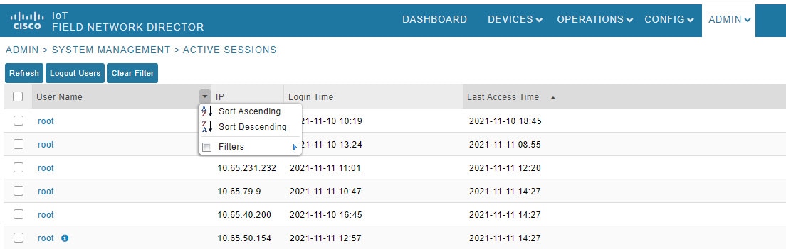 For example, to list the active sessions for the root user, enter root.
|


 Feedback