Managing System Settings
This section describes how to manage system settings, and includes the following sections:
■![]() Configuring Provisioning Settings
Configuring Provisioning Settings
Note: To manage system settings, you must be logged in either as root or as a user with Administrative Operations permissions.
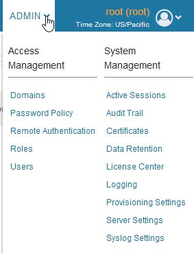
System settings are managed from the ADMIN > System Management menu (Admin Menu)
Managing Active Sessions
IoT FND tracks active user sessions and lets you log out users.
■![]() Filtering the Active Sessions List
Filtering the Active Sessions List
Viewing Active Sessions
To view active user sessions, choose ADMIN > System Management > Active Sessions. IoT FND displays the Active Sessions page (Active Sessions Page).
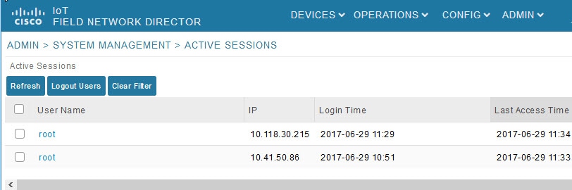
Active Session Fields describes the Active Session fields.
|
|
|
|---|---|
The user name in the session record. To view user settings, click the user name. |
|
The IP address of the system the user employs to access IoT FND. |
|
Logging Users Out
1.![]() Choose ADMIN > System Management > Active Sessions.
Choose ADMIN > System Management > Active Sessions.
2.![]() Select the check boxes for those users you want to log out.
Select the check boxes for those users you want to log out.
Filtering the Active Sessions List
To filter the Active Sessions list using column filtering:
1.![]() Choose ADMIN > System Management > Active Sessions.
Choose ADMIN > System Management > Active Sessions.
2.![]() From the User Name drop-down menu, choose Filters and enter the user name or the first characters in the user name to filter the list.
From the User Name drop-down menu, choose Filters and enter the user name or the first characters in the user name to filter the list.
Figure 3 ADMIN > System Management > Active Sessions Page
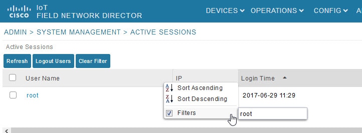
For example, to list the active sessions for the root user, enter root.
Tip: To remove the filter, from the User Name drop-down menu, clear the Filters![]() check box or click Clear Filter.
check box or click Clear Filter.
Multi-Tenancy Support
Multi-Tenancy provides the following capabilities:
■![]() Role-Based Access Control Management (RBAC)
Role-Based Access Control Management (RBAC)
User Domain Management
A user can belong to multiple domains. This feature enables the user to switch to different domains and perform operations within those domains. The domain switch behaves like single sign-on access. After accessing the domain switch, the user is redirected to the dashboard. The resources shown and the operations performed are specific to the new domain.
Users can have different roles in different domains. In a domain d1, a user could have administrator role and monitor only role, where as in other domain d2, a user could have only an administrator role. A default domain also needs to be specified during user creation. This default domain can be changed during user edit.
Domain Names During Login
User names are unique and as such, you no longer need to provide the domain name during login. When you log in, you are automatically logged into your default domain. The database automatically retrieves your default domain from the database (db).
Add a User
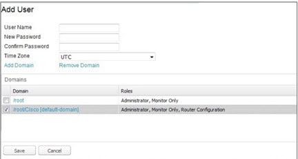
1.![]() To add a user, choose ADMIN > ACCESS MANAGEMENT > USERS. Enter the user name, password and reenter the password to confirm (ADMIN > ACCESS MANAGEMENT > USERS’).
To add a user, choose ADMIN > ACCESS MANAGEMENT > USERS. Enter the user name, password and reenter the password to confirm (ADMIN > ACCESS MANAGEMENT > USERS’).
2.![]() Select the time zone in which that user works from the drop-down menu. Click the boxes next to all of the domains which are relevant to the user. Click Save.
Select the time zone in which that user works from the drop-down menu. Click the boxes next to all of the domains which are relevant to the user. Click Save.
Figure 4 ADMIN > ACCESS MANAGEMENT > USERS’
Add, Edit or Delete a Domain Associated with a User
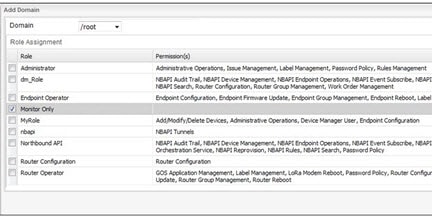
■![]() To add a domain to the user, click Add Domain. Next, check the box(es) next to every Domain listed to which the user should have access (Select Domains to Add to a User). Click Save. The added domain appears noting all the supported roles for that user (ADMIN > ACCESS MANAGEMENT > USERS’).
To add a domain to the user, click Add Domain. Next, check the box(es) next to every Domain listed to which the user should have access (Select Domains to Add to a User). Click Save. The added domain appears noting all the supported roles for that user (ADMIN > ACCESS MANAGEMENT > USERS’).
■![]() To edit a domain for a user, click Add Domain. Next, uncheck the box(es) next to the Domain(s) and its users that you want to remove from the domain. The revised domain(s) appear(s) under the Domains listing at the bottom of the page.
To edit a domain for a user, click Add Domain. Next, uncheck the box(es) next to the Domain(s) and its users that you want to remove from the domain. The revised domain(s) appear(s) under the Domains listing at the bottom of the page.
■![]() To remove a domain from a user, click Remove Domain (ADMIN > ACCESS MANAGEMENT > USERS’) and select the box(es) next to the Domain(s) that you want to remove. Click Save.
To remove a domain from a user, click Remove Domain (ADMIN > ACCESS MANAGEMENT > USERS’) and select the box(es) next to the Domain(s) that you want to remove. Click Save.
When you delete a domain, the following associated resources will also be deleted:
To change the Domains assigned to a user, click Add Domain or Remove Domain at the Add user panel (Select Domains to Add to a User).
In the panel that appears, select the Domains that you want edit or remove.
Note: You can only Remove a domain when it has no users or active jobs associated with it.
Figure 5 Select Domains to Add to a User
Switch Domains
1.![]() To switch to a new domain, select the Switch Domain option under the root menu.
To switch to a new domain, select the Switch Domain option under the root menu.
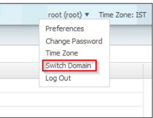
2.![]() When you log into a specific switch domain, you will see a list of all other domains in which you are a member except the domain in which you are currently logged into.
When you log into a specific switch domain, you will see a list of all other domains in which you are a member except the domain in which you are currently logged into.
Domain Deletion
You can only delete Domains when the following two conditions are met:
■![]() No devices or users are associated with the Domain
No devices or users are associated with the Domain
■![]() No active jobs are associated with the Domain
No active jobs are associated with the Domain
Note![]() : You cannot remove a root domain.
: You cannot remove a root domain.
Note: You must remove all users and domains associated with the domain before you delete it.
When you delete a domain, all resources (events, issues, labels) associated with that domain are deleted as well.
To delete a Domain, do the following:
1.![]() Click ADMIN > ACCESS MANAGEMENT > DOMAINS.
Click ADMIN > ACCESS MANAGEMENT > DOMAINS.
2.![]() Check the box next to the listed Domain you want to delete.
Check the box next to the listed Domain you want to delete.
3.![]() Click the Delete button. (found above the Domain list).
Click the Delete button. (found above the Domain list).
4.![]() In the panel that appears, click Yes to confirm that you want to delete the domain. If there is a root user in the domain you will not be able to delete the Domain.
In the panel that appears, click Yes to confirm that you want to delete the domain. If there is a root user in the domain you will not be able to delete the Domain.
Audit Trail
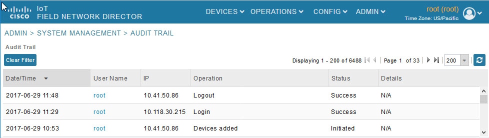
Use the audit trail to track IoT Field Network Director user activity. Audit trails are also associated with the domain. All the calls to the audit trail APIs will be updated to send the logged in user's domain.
To display the Audit Trail, choose ADMIN > System Management > Audit Trail page.
Figure 6 ADMIN > System Management > Audit Trail
Audit Trail Fields describes the Audit Trail fields.
|
|
|
|---|---|
The user who performed the operation. To view user settings, click the user name. |
|
IP address of the system that the user employs to access IoT FND. |
|
Tip: In ADMIN > System Management > Audit Trail, click the Refresh icon (circular arrows) at the far right of the panel to update the list.
Filtering the Audit Trail List
To filter the Audit Trail list using column filtering:
1.![]() Choose ADMIN > System Management > Audit Trail.
Choose ADMIN > System Management > Audit Trail.
2.![]() From the User Name drop-down menu, pass over Filters option and in the field that appears enter the user name or the first characters of the user name to filter the list.
From the User Name drop-down menu, pass over Filters option and in the field that appears enter the user name or the first characters of the user name to filter the list.
For example, to list the Audit Trail entries for the user jane, enter jane.
Tip: To remove the filter, from the User Name drop-down menu, uncheck the Filters![]() check box or click Clear Filter (left of the screen).
check box or click Clear Filter (left of the screen).
Role-Based Access Control Management (RBAC)
When defining a new domain, Root users define a Domain Administrator (DA) and select one of the following options for that person: Local, Existing User or Remote (selectable on the entry panel). Users can be assigned a different role in each domain in which the user is a member.
The Domain Administrator, has the following permissions: User Management, Role Management, Issue Management, Label Management and Rules Management. This role is similar to the administrator role but it is not shown at the Root level.
The system defined roles (except Administrator) will be inherited to all other domains.
1.![]() Choose ADMIN > System Management > Role.
Choose ADMIN > System Management > Role.
Note: The Administrator Role for non-root domain users is not shown because the administrator role includes the Administrative Operations permission which enables the user to change settings like Password Policy and Remote Authentication server which is not recommended for non-root domain users.
Managing Certificates
The Certificates page displays the certificates for CSMP (CoAP Simple Management Protocol), IoT-DM (IoT Device Manager), and Web used by IoT FND and lets you download these certificates.
To display the CSMP, IoT-DM and Web certificates:
1.![]() Choose ADMIN > System Management > Certificates.
Choose ADMIN > System Management > Certificates.
2.![]() To view a certificate, click its corresponding heading (such as Certificate for Routers).
To view a certificate, click its corresponding heading (such as Certificate for Routers).
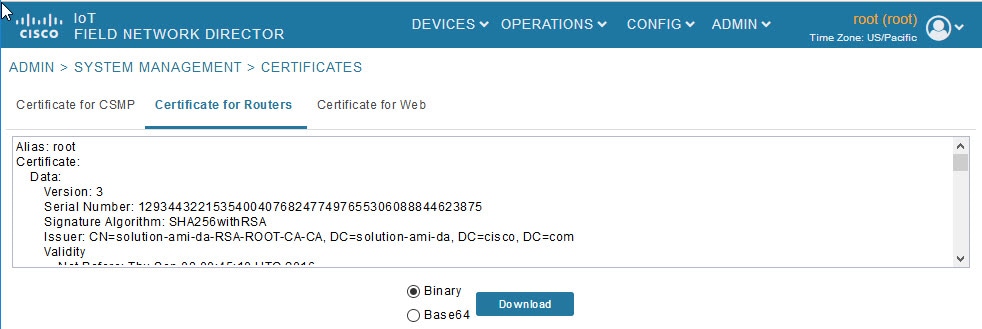
3.![]() To download a certificate, select encoding type (Binary or Base64) radio button, and then click Download.
To download a certificate, select encoding type (Binary or Base64) radio button, and then click Download.
For more information about certificates, see “Generating and Installing Certificates” in the Cisco IoT Field Network Director Installation Guide.
Configuring Data Retention
The Data Retention page lets you determine the number of days to keep event, issue, and metric data in the IoT FND database.
Note: Data retention prunes events even if they have associated open issues.
To set IoT FND data retention:
1.![]() Choose ADMIN > System Management > Data Retention.
Choose ADMIN > System Management > Data Retention.
2.![]() For each of the retention categories, specify the number of days to retain data.
For each of the retention categories, specify the number of days to retain data.
Data Retention Fields Allowable Maximum Values lists the allowable maximum values for each field.
|
|
|
||
|---|---|---|---|
|
|
|
|
|
Managing Licenses
The License Center page, ADMIN > System Management > License Center, lets you view and manage license files.
Note: IoT FND performs license enforcement when importing devices. If you add licenses, IoT FND only allows the permitted number of devices to be imported, as defined in the licenses.
Without licenses, IoT FND allows only 3 routers and 100 mesh endpoints.
Viewing License Summary
To view IoT FND license summary:
1.![]() Choose ADMIN > System Management > License Center.
Choose ADMIN > System Management > License Center.
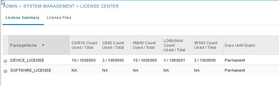
For every license, IoT FND displays the information described in Device License Summary Information.
Note: IR500s use mesh endpoint licenses, and require no special license.
Viewing License Files
To view IoT FND license files:
1.![]() Choose ADMIN > System Management > License Center.
Choose ADMIN > System Management > License Center.
2.![]() Click License Files to display details on all active licenses.
Click License Files to display details on all active licenses.

For every file, IoT FND displays the fields described in License File Fields.
|
|
|
|---|---|
Adding License Files
1.![]() Choose ADMIN > System Management > License Center.
Choose ADMIN > System Management > License Center.
3.![]() Click Add to open a search window.
Click Add to open a search window.
4.![]() Click Browse to locate the desired license file and then click Open.
Click Browse to locate the desired license file and then click Open.
5.![]() Click Upload. To cancel the upload, click Reset.
Click Upload. To cancel the upload, click Reset.
6.![]() Click Reset to cancel the selected file and search for another file.
Click Reset to cancel the selected file and search for another file.
Deleting License Files
Note: Ensure that you have access to license files before deleting existing license files. Without licenses, IoT FND allows registration of only 3 routers and 100 mesh endpoints.
To delete a single license or multiple license files:
1.![]() Choose ADMIN > System Management > License Center.
Choose ADMIN > System Management > License Center.
3.![]() Select the box next to each license file that you want to delete.
Select the box next to each license file that you want to delete.
4.![]() Click Delete. To confirm deletion, click Yes. To cancel the action, click No.
Click Delete. To confirm deletion, click Yes. To cancel the action, click No.
Managing Logs
Configuring Log Settings
IoT FND lets you change the logging level for the various log categories and download the logs. Logs incur a certain amount of disk space. For example, for 5 million meters at an 8-hour reporting interval and 5000 routers at a 60-minute periodic inventory notification, disk consumption is approximately 7MB/sec. Ensure that your server has enough disk space to contain your logs.
To configure the logging level:
1.![]() Choose ADMIN > System Management > Logging.
Choose ADMIN > System Management > Logging.
3.![]() Check the check boxes of all logging categories to configure.
Check the check boxes of all logging categories to configure.
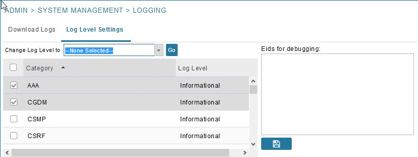
4.![]() From the Change Log Level to drop-down menu, choose the logging level setting (Debug or Informational).
From the Change Log Level to drop-down menu, choose the logging level setting (Debug or Informational).
5.![]() To apply the configuration, click Go.
To apply the configuration, click Go.
Downloading Logs
1.![]() Choose ADMIN > System Management > Logging.
Choose ADMIN > System Management > Logging.
2.![]() Click the Download Logs tab.
Click the Download Logs tab.
3.![]() Click the Download Logs button.
Click the Download Logs button.
4.![]() To download a zip file locally, click its file name.
To download a zip file locally, click its file name.
Tip: In a cluster environment, if you need to send log files to Cisco Support, ensure that you send the log files of all cluster servers.
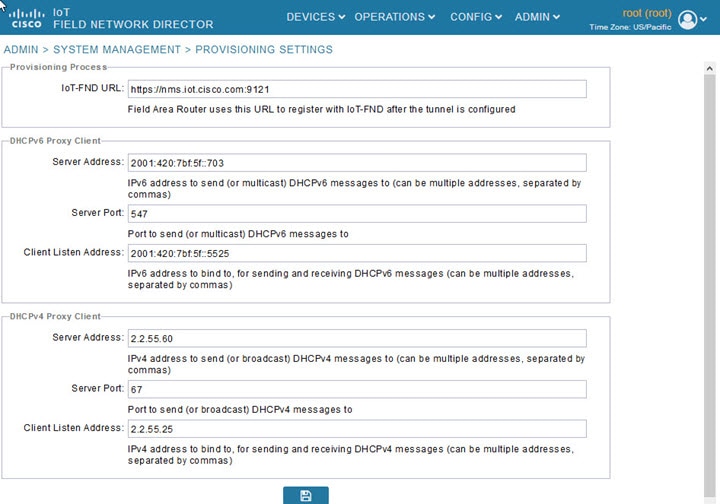
Configuring Provisioning Settings
The Provisioning Settings page (ADMIN > System Management > Provisioning Settings) lets you configure the IoT FND URL, DHCPv4 Proxy Client, and DHCPv6 Proxy Client settings required for IoT FND to create tunnels between routers and ASRs (Provisioning Settings Page). See Zero Touch Deployment Architecture for an example of tunnels as used in the IoT FND architecture. See “Tunnel Provisioning Configuration Process for information on provisioning tunnels in the “Managing Tunnel Provisioning” chapter in the
I oT FND 4.0 Installation Guide. During ZTD, you can add DHCP calls to the device configuration template for leased IP addresses.
Note: For Red Hat Linux 7.x server installations, you must configure specific IPv4 and IPv6 addresses from the IoT FND Linux host server to which to bind DHCP IPv4 and IPv6 clients by setting the following values in IoT FND:
Note: To configure tunnel and proxy settings, you must be logged in either as root or as a user with Administrative Operations permissions.
Figure 7 Provisioning Settings Page
This section provides the following topics for configuring tunnel settings:
■![]() Configuring the IoT FND Server URL
Configuring the IoT FND Server URL
■![]() Configuring DHCPv6 Proxy Client
Configuring DHCPv6 Proxy Client
■![]() Configuring DHCPv4 Proxy Client
Configuring DHCPv4 Proxy Client
Configuring the IoT FND Server URL
The IoT FND URL is the URL that routers use to access with IoT FND after the tunnel is established. This URL is also accessed during periodic inventories. During ZTD, routers transition from accessing IoT FND through the TPS proxy to using this URL, which must be appropriate for use through the tunnel.
1.![]() Choose ADMIN > System Management > Provisioning Settings.
Choose ADMIN > System Management > Provisioning Settings.
2.![]() In the IoT FND URL field, enter the URL of the IoT FND server.
In the IoT FND URL field, enter the URL of the IoT FND server.
The URL must use the HTTPS protocol and include the port number designated to receive registration requests. By default, the port number is 9121. For example:
Configuring DHCPv6 Proxy Client
To configure DHCPv6 Proxy Client settings:
1.![]() Choose ADMIN > System Management > Provisioning Settings.
Choose ADMIN > System Management > Provisioning Settings.
2.![]() Configure the DHCPv6 Proxy Client settings:
Configure the DHCPv6 Proxy Client settings:
a.![]() In the Server Address field, enter the address of the DHCPv6 server that provides tunnel IP addresses.
In the Server Address field, enter the address of the DHCPv6 server that provides tunnel IP addresses.
You can enter multiple addresses separated by commas. However, in most cases, you only need one server. IoT FND tries to get the tunnel IP addresses using DHCP protocols. If it cannot, it goes to the next server in the list and so on.
b.![]() In the Server Port field, enter the port address on the DHCP server to send DHCPv6 requests.
In the Server Port field, enter the port address on the DHCP server to send DHCPv6 requests.
Note: Do not change the default port number (547) unless you have configured your DHCP server to operate on a non-standard port.
c.![]() In the Client Listen Address field, enter the address to bind to for DHCPv6 send and receive messages.
In the Client Listen Address field, enter the address to bind to for DHCPv6 send and receive messages.
This is the address of the interface that the DHCP server uses to communicate with IoT FND. You can enter multiple backup addresses separated by commas.
Tip: For IoT FND installations where the host has multiple interfaces, the client sends requests using each listed source address. The default values, “0.0.0.0” (IPv4) and “::” (IPv6), cause the client to send requests out each interface. Usually, one interface faces the DHCP server(s). In these installations, setting the Client Listen Address field to the IP address of the facing interface sends all client requests out that interface.
Configuring DHCPv4 Proxy Client
To configure DHCPv4 Proxy Client settings:
1.![]() Choose ADMIN > System Management > Provisioning Settings.
Choose ADMIN > System Management > Provisioning Settings.
2.![]() Configure the DHCPv4 Proxy Client settings:
Configure the DHCPv4 Proxy Client settings:
a.![]() In the Server Address field, enter the address of the DHCPv4 server that provides tunnel IP addresses.
In the Server Address field, enter the address of the DHCPv4 server that provides tunnel IP addresses.
You can enter multiple addresses separated by commas. However, in most cases, you only need one server. IoT FND tries to get the tunnel IP addresses from the first server in the list. If it cannot, it moves to the next server in the list, and so on.
b.![]() In the Server Port field, enter the port address on the DHCP server to send DHCPv4 requests to.
In the Server Port field, enter the port address on the DHCP server to send DHCPv4 requests to.
Note: Do not change the default port number (67) unless you have configured your DHCP server to operate on a non-standard port.
c.![]() In the Client Listen Address field, enter the address to bind to for send and receive DHCPv4 messages.
In the Client Listen Address field, enter the address to bind to for send and receive DHCPv4 messages.
This is the address of the interface that the DHCP server uses to communicate with IoT FND. You can enter multiple backup addresses separated by commas.
Configuring Server Settings
The Server Settings page (ADMIN > System Management > Server Settings) lets you view and manage server settings.
■![]() Configuring Download Logs Settings
Configuring Download Logs Settings
■![]() Configuring Device Down Timeouts
Configuring Device Down Timeouts
■![]() Configuring Billing Period Settings
Configuring Billing Period Settings
■![]() Configuring the Issue Status Bar
Configuring the Issue Status Bar
Configuring Download Logs Settings
Note: Configuring download log settings is only required for IoT FND cluster setup.
The Download Logs page lets you configure the Keystore settings.
To configure Download Logs settings:
1.![]() Choose ADMIN > System Management > Server Settings.
Choose ADMIN > System Management > Server Settings.
2.![]() Click the Download Logs tab.
Click the Download Logs tab.
Configuring Web Sessions
The Web Sessions page lets you specify the number of timeout seconds after which IoT FND terminates web sessions and logs users out.
To configure web session timeout:
1.![]() Choose ADMIN > System Management > Server Settings.
Choose ADMIN > System Management > Server Settings.
3.![]() Enter the number of timeout seconds. Valid values are 0–86400 (24 hours).
Enter the number of timeout seconds. Valid values are 0–86400 (24 hours).
If a web session is idle for the specified amount of time, IoT FND terminates the session and logs the user out.
Configuring Device Down Timeouts
The Device Down Timeouts page lets you specify the number of timeout seconds after which the status of Head-end routers (ASR) and Routers (CGR1000, IR800, C800, ESR) and Endpoints changes to Down in IoT FND. The device down poll interval is five minutes. The system uses the device down timeouts values and the last heard time to decide whether to change the device status to Down. For example, if the router device down timeout value is set to two hours (7200 seconds), all routers with a last heard time older than 2 hours are marked as status Down.
You can also configure the device timeout setting for router Config groups and Endpoint Config Groups.
Device status changes to Up when IoT FND detects any of the following:
■![]() Periodic inventory notifications
Periodic inventory notifications
To configure device down timeout settings:
1.![]() Choose ADMIN > System Management > Server Settings.
Choose ADMIN > System Management > Server Settings.
2.![]() Click the Device Down Timeouts tab.
Click the Device Down Timeouts tab.
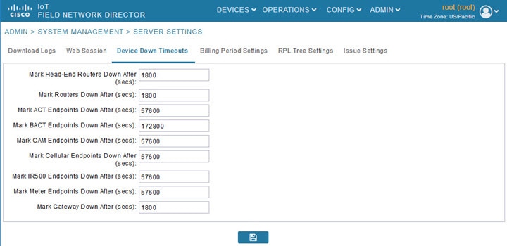
3.![]() For each device type listed, enter the number of seconds after which the device status changes to Down in IoT FND.
For each device type listed, enter the number of seconds after which the device status changes to Down in IoT FND.
The parameter value must be greater than the corresponding polling intervals. For example, the default polling interval for endpoints is 8 hours (28800 seconds), so the value in the Mark {ACT | BACT | CAM | Cellular | IR500> Meter} Endpoints Down After (secs) field must be greater than 28800.
4.![]() To save the configuration, click the disk icon.
To save the configuration, click the disk icon.
Device Down Timeout Settings for Router Config Groups and Endpoint Config Groups
To configure device down timeout settings for Router Config groups or Endpoint Config Groups:
1.![]() Choose CONFIG > Device Configuration.
Choose CONFIG > Device Configuration.
2.![]() Select the Device you want to configure { ROUTER | ENDPOINT} in the left pane.
Select the Device you want to configure { ROUTER | ENDPOINT} in the left pane.
3.![]() Click the Group Properties tab.
Click the Group Properties tab.
4.![]() In the Mark Routers Down After (secs) field, enter the number of seconds after which the status of the devices (router or endpoints) in the group changes to Down in IoT FND.
In the Mark Routers Down After (secs) field, enter the number of seconds after which the status of the devices (router or endpoints) in the group changes to Down in IoT FND.
This value must be greater than the corresponding polling interval.
For example, the default polling interval for routers is 30 minutes (1800 seconds), so the value in the Mark Routers Down After (secs) field must be 1801 or greater.
The default polling interval for ENDPOINTS is 960 minutes (57600 seconds), so the value in the Mark Routers Down After (secs) field must be greater than 57600 seconds.
Configuring Billing Period Settings
IoT FND lets you configure the start day of the monthly billing periods for cellular and Ethernet (satellite) services.
To configure the billing period settings:
1.![]() Choose ADMIN > System Management > Server Settings.
Choose ADMIN > System Management > Server Settings.
2.![]() Click the Billing Period Settings tab.
Click the Billing Period Settings tab.
3.![]() Enter the starting days for the cellular and Ethernet billing periods.
Enter the starting days for the cellular and Ethernet billing periods.
4.![]() From the drop-down menu, choose the time zone for the billing period.
From the drop-down menu, choose the time zone for the billing period.
Configuring RPL Tree Polling
RPL tree polls are derived from router periodic notification events. Since the RPL tree is not pushed from the router with the periodic notification event, IoT FND must explicitly poll for the RPL tree at the configured intervals. IoT FND lets you configure the RPL tree polling cycle (that is, how many periodic notification events occur between RPL tree polls), and set the maximum amount of time between tree polls.
Caution: CG-NMS 1.1(5) release does not support router RPL tree updates. Do not enable RPL tree updates from Routers.
To configure RPL tree polling settings:
1.![]() Choose ADMIN > System Management > Server Settings.
Choose ADMIN > System Management > Server Settings.
2.![]() Choose the RPL Tree Settings tab.
Choose the RPL Tree Settings tab.
3.![]() Choose the Enable RPL tree update from radio button for Mesh Nodes to receive the RPL tree update from those devices.
Choose the Enable RPL tree update from radio button for Mesh Nodes to receive the RPL tree update from those devices.
Configuring the Issue Status Bar
The Issue Status bar displays issues by device type (as set in user preferences) and severity level in the lower-left browser frame.
To enable the Issue Status bar and configure the refresh interval:
1.![]() Choose ADMIN > System Management > Sever Settings > Issue Settings.
Choose ADMIN > System Management > Sever Settings > Issue Settings.
2.![]() To display the Issue status bar in the browser frame, check the Enable/Disable Issue Status Bar check box.
To display the Issue status bar in the browser frame, check the Enable/Disable Issue Status Bar check box.
3.![]() In the Issue Status Bar Refresh Interval (seconds) field, enter a refresh value in seconds.
In the Issue Status Bar Refresh Interval (seconds) field, enter a refresh value in seconds.
| ■ |
4.![]() In the Certificate Expiry Threshold (days) field for all supported routers or an IoT FND application server, enter a value in days.
In the Certificate Expiry Threshold (days) field for all supported routers or an IoT FND application server, enter a value in days.
Note: When the configured Certificate Expiry Threshold default date is met, a Major event, certificateExpiration, is created. When the Certificate has expired (>180 days), a Critical event, certificateExpired, is created.
Managing the Syslog
When IoT FND receives device events it stores them in its database and sends syslog messages to a syslog server that allows third-party application integration.
To configure Syslog forwarding:
1.![]() Choose ADMIN > System Management > Syslog Settings.
Choose ADMIN > System Management > Syslog Settings.
2.![]() In the Syslog Server IP Address field, enter the IP address of the Syslog server.
In the Syslog Server IP Address field, enter the IP address of the Syslog server.
3.![]() In the Syslog Server Port Number field, enter the port number (default is 514) over which to receive device events.
In the Syslog Server Port Number field, enter the port number (default is 514) over which to receive device events.
| ■ |
| ■ |
For IoT FND cluster solutions, each server in the cluster sends events to the same Syslog server.
 Feedback