Overview of Cisco C-NIM-4X, C-NIM-8M, and C-NIM-8T Module Network Interface Module
The Cisco C-NIM-4X, C-NIM-8M, and C-NIM-8T are the next generation Form-factor LAN/WAN NIM modules that provide enhanced security, reliability, and performance. The Cisco C-NIM-4X module provides Small Form-Factor Pluggable Plus (SFP+), 10G and 1 Gigabit connectivity. The Cisco C-NIM-8T module provides 1 Gigabit RJ45 connectivity supporting 100 Mbps. Similarly, the Cisco C-NIM-8M module provides 2.5 Gbps mGig connectivity and supports UPoE+. Also, Cisco C-NIM-4X, C-NIM-8M, and C-NIM-8T support Layer 2 and Layer 3 configurable Ethernet network. The Cisco C-NIM-4X, Cisco C-NIM-8M, ard C-NIM-8T modules are supported only in a NIM slot. These modules are not supported in the SM-NIM Carrier Adapter (C-SM-NIM-ADPT). You can install a Cisco C-NIM-8M or C-NIM-8T Network Interface module on the Cisco Catalyst 8200 and 8300 Series Edge Platforms. However, the Cisco C-NIM-4X is supported only on the Cisco Catalyst 8300 Series Edge Platforms.
This article describes how to install the C-NIM-4X or C-NIM-8M or C-NIM-8T Network Interface module in the Cisco Catalyst 8200 and 8300 Series Edge platforms. This chapter also includes the installation of Small-Form-Factor pluggable (SFP+) modules. It also describes how to connect the module in your network.
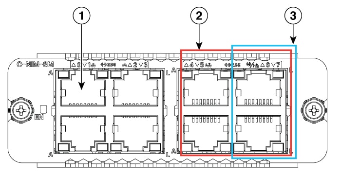
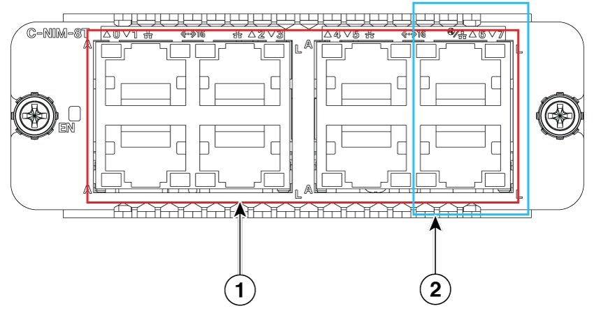
Figure shows the front panel of the C-NIM-4X or C-NIM-8M or C-NIM-8T Network Interface module.
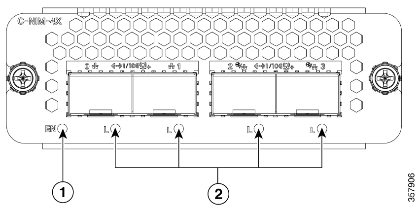
This table explains the led description for C-NIM-4X Network Interfaces:
|
LED |
Color |
Description |
|
|---|---|---|---|
|
1 |
LED EN (Enable) |
Green/Amber |
Off – Power off Solid Green – Power on and operate normally Solid Amber – Power or operating failure |
|
2 |
SFP Ports L (Link) |
Green/Amber |
Off – No link. SFP is not detected or inserted. Solid Green – SFP link up Solid Amber – SFP is not supported or in a fault state |
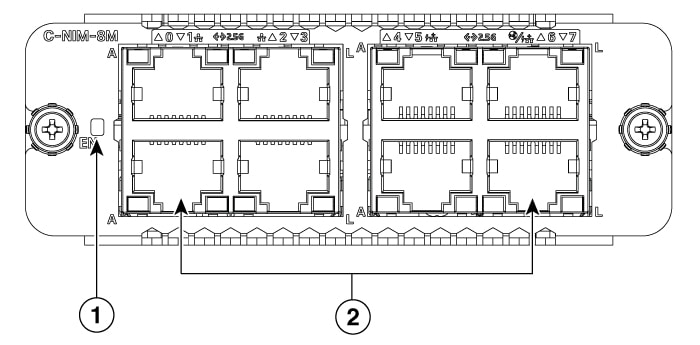
This table explains the led description for C-NIM-8M Network Interfaces:
|
LED |
Color |
Description |
|||
|---|---|---|---|---|---|
|
1 |
LED EN (Enable) |
Green/Amber |
Off – Power off Solid Green – Power on and operate normally Solid Amber – Power or operating failure |
||
|
2 |
BASE-T Ports, w/ PoE L (Link) |
Green/Amber |
Off: No link Green Steady On: Link Up Amber Steady On: POE power denied due to fault (power denied, or short detected)
|
||
| A (Active) |
Green |
Off: No Data Green Blinking: TX/RX Data |
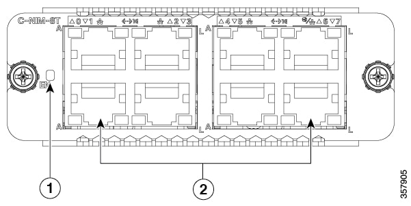
This table explains the led description for C-NIM-8T Network Interfaces:
|
LED |
Color |
Description |
|
|---|---|---|---|
|
1 |
LED EN (Enable) |
Green/Amber |
Off – Power off Solid Green – Power on and operate normally Solid Amber – Power or operating failure |
|
2 |
BASE-T Ports L (Link) |
Green |
Off: No link Green Steady On: Link Up |
| A (Active) |
Green |
Off: No Data Green Blinking: TX/RX Data |
Supported Platforms
The following table provides information on Cisco Catalyst 8200 and 8300 platforms that support the Cisco C-NIM-4X, C-NIM-8M, and C-NIM-8T modules.
|
Platforms |
C-NIM-4X |
C-NIM-8M |
C-NIM-8T |
|---|---|---|---|
|
C8300-2N2S-4T2X |
Yes |
Yes |
Yes |
|
C8300-2N2S-6T |
Yes |
Yes |
Yes |
|
C8300-1N1S-4T2X |
Yes |
Yes |
Yes |
|
C8300-1N1S-6T |
Yes |
Yes |
Yes |
|
C8200-1N-4T |
— |
Yes |
Yes |
|
C8200L-1N-4T |
— |
Yes (with 1G uplink) |
Yes (with 1G uplink) |
Preparing for Installation
The following sections describe safety warnings, general maintenance guidelines, and safety recommendations that you must read before installing and using the service module:
Safety Warnings
 DANGER |
Read the installation instructions before connecting the system to the power source. Statement 1004 |
DANGER |
Only trained and qualified personnel should be allowed to install, replace, or service this equipment. Statement 1030 |
DANGER |
Before working on equipment that is connected to power lines, remove jewelry (including rings, necklaces, and watches). Metal objects heat up when connected to power and ground and can cause serious burns or may weld the metal object to the terminals. Statement 43 |
DANGER |
Do not use this product near water; for example, near a bath tub, wash bowl, kitchen sink or laundry tub, in a wet basement, or near a swimming pool. Statement 1035 |
DANGER |
Never install telephone jacks in wet locations unless the jack is specifically designed for wet locations. Statement 1036 |
DANGER |
Never touch uninsulated telephone wires or terminals unless the telephone line has been disconnected at the network interface. Statement 1037 |
DANGER |
Avoid using a telephone (other than a cordless type) during an electrical storm. There may be a remote risk of electric shock from lightning. Statement 1038 |
DANGER |
To report a gas leak, do not use a telephone in the vicinity of the leak. Statement 1039 |
DANGER |
There is the danger of explosion if the battery is replaced incorrectly. Replace the battery only with the same or equivalent type recommended by the manufacturer. Dispose of used batteries according to the manufacturer's instructions. Statement 1015 |
DANGER |
Blank faceplates and cover panels serve three important functions: they prevent exposure to hazardous voltages and currents inside the chassis; they contain electromagnetic interference (EMI) that might disrupt other equipment; and they direct the flow of cooling air through the chassis. Do not operate the system unless all cards, faceplates, front covers, and rear covers are in place. Statement 1029 |
DANGER |
For connections outside the building where the equipment is installed, the following ports must be connected through an approved network termination unit with integral circuit protection. Statement 1044 |
Preventing Electrostatic Discharge Damage
Electrostatic discharge can damage equipment and electrical circuitry. Electrostatic discharge occurs when electronic printed circuit cards, such as those used in Cisco service modules, are not handled properly. Improper handling can result in complete or intermittent equipment failure. Always observe the following procedures to prevent electrostatic discharge damage (ESD) when installing, removing, or replacing any electronic printed circuit cards:
-
Make sure that the router chassis is electrically connected to earth ground.
-
Wear an ESD-preventive wrist strap, and make sure that it makes good contact with your skin.
-
Connect the wrist strap clip to an unpainted portion of the chassis frame to channel unwanted ESD voltages to ground.
-
The wrist strap and clip must be used correctly to ensure proper ESD protection. Periodically confirm that the resistance value of the ESD-preventive wrist strap is between 1 and 10 megohms (Mohm).
-
If no wrist strap is available, ground yourself by touching a metal part of the router chassis.
General Maintenance Guidelines and Safety Recommendations for Cisco C-NIM-4X, C-NIM-8M, and C-NIM-8T Module
General Maintenance Guidelines
-
Keep the router chassis area clear and dust-free during and after installation.
-
If you remove the chassis cover for any reason, store it in a safe place.
-
Do not perform any action that creates a hazard to people or makes equipment unsafe.
-
Keep walk areas clear to prevent falls or damage to equipment.
-
Follow installation and maintenance procedures as documented by Cisco Systems, Inc.
-
Always wear an electrostatic discharge (ESD)-preventive wrist strap, and ensure that it makes good contact with your skin when you remove or install an Service Module (SM). Connect the equipment end of the wrist strap to a metal part of the chassis.
-
Handle the NIMs only by their edges. SMs are ESD-sensitive components and can be damaged by mishandling.
Safety Recommendations
To prevent hazardous conditions, follow these safety recommendations while working with this equipment:
-
Keep tools away from walk areas where you or others could trip over them.
-
Do not wear loose clothing around the router. Fasten your tie or scarf and roll up your sleeves to prevent clothing from being caught in the chassis.
-
Wear safety glasses when working under any conditions that might be hazardous to your eyes.
-
Locate the emergency power-off switch in the room before you start working. If an electrical accident occurs, shut the power off.
-
Before working on the router, turn off the power and unplug the power cord.
-
Disconnect all power sources before doing the following:
-
Installing or removing a router chassis
-
Working near power supplies
-
-
Do not work alone if potentially hazardous conditions exist.
-
Always check that power is disconnected from a circuit.
-
Remove, from your work area, possible hazards such as damp floors, ungrounded power extension cables, or missing safety grounds.
-
If an electrical accident occurs to another person with you, proceed as follows:
-
Turn off power to the room using the emergency power-off switch.
-
Determine the condition of the victim and send another person to get medical aid or call for help.
-
Determine if the person needs rescue breathing or external cardiac compressions; then take appropriate action.
-
Software Requirements for Installing Cisco C-NIM-4X, C-NIM-8M, and C-NIM-8T Moduled
Cisco IOS XE Dublin 17.11.1a or a later release is required to install the Cisco C-NIM-4X and C-NIM-8T Network Interface modules. To install the C-NIM-8M module, you require the Cisco IOS XE Dublin 17.13.1a release or a later release.
To determine the version of Cisco IOS software that is running on your router, log in to the router and enter the show version command:
Router> show version Cisco IOS Software [IOSXE], c8000be Software (X86_64_LINUX_IOSD-UNIVERSALK9-M), Experimental Version 17.13.20231016:054102
Technical Support: http://www.cisco.com/techsupport
Copyright (c) 1986-2023 by Cisco Systems, Inc.
Compiled Sun 15-Oct-23 04:16 by XYZ
Installing Cisco C-NIM-4X, C-NIM-8M, and C-NIM-8T Modules
This section describes how to install the Cisco C-NIM-4X, C-NIM-8M, and C-NIM-8T network interface modules. This section describes the installation procedure that is common for all C-NIM-4X, C-NIM-8M, and C-NIM-8T modules.
For more information on the specification of these modeules, see the Cisco Catalyst 8000 Series Gigabit Ethernet LAN/WAN Modules Data Sheet.
Note |
For illustration purposes, we have used images of C-NIM-4X, C-NIM-8M, and C-NIM-8T. |
You need to install the module and then reload the device. If the module is not inserted then the device will be in legacy mode. When you insert the module, the system displays a message as is not compatible with current mode and the device cannot work in this mode. You need to reload the device Otherwise, you must power down the device and insert the module. After inserting the module, power up the device.
A system message displays: :Jan 5 09:13:15.795: %IOMD-3-UNSUPPORTED_SWITCH_MODULE: C0/1: iomd:
Note |
The message denotes that the system is in legacy mode. For C-NIM-4X, C-NIM-8M, and C-NIM-8T modules to work in Flex-Switch mode, you need to reload the device. |
 Caution |
Always wear an electrostatic discharge (ESD)-preventive wrist strap and ensure that it makes good contact with your skin when you install or remove the C-NIM-4X or C-NIM-8T or C-NIM-8T network interface module. Connect the equipment end of the wrist strap to the metal part of the chassis. |
Caution |
Handle your network interface modules only by their edges. Network interface modules are ESD-sensitive components and can be damaged by mishandling. |
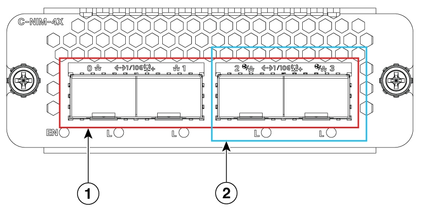
|
1 |
Ports with 4x 1G/10G SFP/SFP+ |
2 |
WAN and LAN Ports |
|
1 |
Ports with 8x 2.5Gbps, RJ45 |
2 |
UPoE Ports |
|
3 |
WAN and LAN Ports |
|
1 |
Ports with 8x 1Gbps, RJ45 |
2 |
WAN and LAN Ports |
Use the following procedure to install the Cisco C-NIM-4X, C-NIM-8M, and C-NIM-8T network interface module on your router:
Procedure
|
Step 1 |
Read the Safety Warnings before you perform any module replacement. |
||
|
Step 2 |
Shut down the electrical power to the slot in the device, turn off the electrical power to the device. Leave the power cable plugged-in to channel ESD voltages to ground. |
||
|
Step 3 |
Remove all network cables from the rear panel of the device. |
||
|
Step 4 |
Remove the blank faceplates installed over the network interface module slot that you intend to use.
|
||
|
Step 5 |
Align the module with the guides in the chassis walls or slot divider and slide it gently into the NIM slot on the device.. |
||
|
Step 6 |
Push the module into place until you feel the edge connector seat securely into the connector on the router backplane. The module faceplate should contact the chassis rear panel |
||
|
Step 7 |
Using a number 1 Phillips screwdriver, tighten the captive screws on the network interface module. |
Removing Cisco C-NIM-4X, C-NIM-8M, and C-NIM-8T Network Interface Module
Use the following procedure to remove the Cisco C-NIM-4X, C-NIM-8M, and C-NIM-8T network interface module from your router:
Procedure
|
Step 1 |
Read the Safety Warnings before you perform any module replacement. |
|
Step 2 |
Shut down the electrical power to the slot in the device, turn off the electrical power to the device. Leave the power cable plugged-in to channel ESD voltages to ground. . |
|
Step 3 |
Using a number 1 Phillips or flat-blade screwdriver, unscrew the captive mounting screws on the module faceplate. |
|
Step 4 |
Slide the Cisco C-NIM-4X, C-NIM-8M, and C-NIM-8T network interface module out of the chassis. |
|
Step 5 |
If you are not replacing the module, install a blank faceplate over the empty slot to ensure proper air flow. |
|
Step 6 |
Place the service module in an antistatic bag to protect it from electrostatic discharge (ESD) damage. |
Verifying the Cisco C-NIM-4X, C-NIM-8M, and C-NIM-8T Network Interface Modules Installation
Use the show platform command to verify that the Cisco C-NIM-4X, C-NIM-8M, and C-NIM-8T Network Interface modules are installed. The following example shows that the C-NIM-4X, C-NIM-8M, and C-NIM-8T Network Interface module are installed and recognized by the system.
The following is sample output of the show platform command.
Device# show platform

Slot      Type                State                 Insert time (ago)
--------- ------------------- --------------------- -----------------
0         C8300-2N2S-4T2X     ok                    1w0d
 0/0      4x1G-2xSFP+         ok                    1w0d
 0/1      C-NIM-4X            ok                    1w0d
1         C8300-2N2S-4T2X     ok                    1w0d
2         C8300-2N2S-4T2X     ok                    1w0d
R0        C8300-2N2S-4T2X     ok, active            1w0d
F0        C8300-2N2S-4T2X     ok, active            1w0d
P0        PWR-CC1-1000WAC     ok                    1w0d
P1        Unknown             empty                 never
P2        C8300-FAN-2R        ok                    1w0d
POE1      PWR-POE-4450        incompatible          1w0d

Slot      CPLD Version        Firmware Version
--------- ------------------- ---------------------------------------
0         19061924            2RU-20191211
1         19061924            2RU-20191211
2         19061924            2RU-20191211
R0        19061924            2RU-20191211
F0        19061924            2RU-20191211
 Feedback