Cisco ASR-920-12SZ-IM and ASR-920U-12SZ-IM Aggregation Services Router Quick Start Guide
 Note |
The Cisco ASR-920-12SZ-IM and Cisco ASR-920U-12SZ-IM are collectively referred to as the Cisco ASR-920-12SZ-IM Router in this document. Any differences between the routers are specifically called out. |
The Cisco ASR 920 Series Aggregation Services Router is a family of fixed configuration routers that provides common network architecture to the Service Providers for macro and small cell networks.
This router acts as an access device for mobile backhaul services—macro Cell Site Router (CSR) and Small Cell Router (SCR). As an access device, it provides capabilities like 1GE/10GE, MPLS, H-QoS, Services, GPS clocking, PoE and fit within ETSI 300 mm depth cabinet. It can easily be integrated into the Unified MPLS for Mobile Transport (UMMT) and Fixed Mobile Convergence (FMC) solution.
Overview
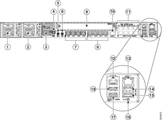
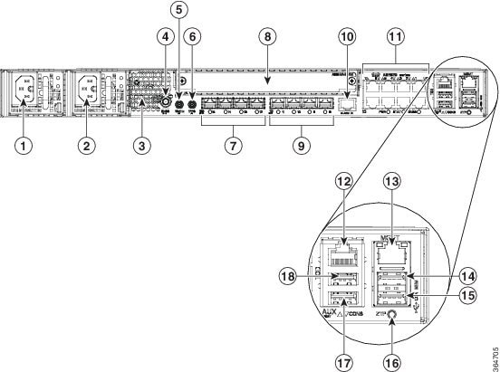
The following figures show the port numbering for the Cisco ASR 920 router:
|
1 |
Power Supply 0 (AC or DC) |
10 |
Alarm port |
||
|---|---|---|---|---|---|
|
2 |
Power Supply 1 (AC or DC) |
11 |
Eight Copper port (1G PoE)
|
||
|
3 |
Front Air-Inlet Area |
12 |
ToD port |
||
|
4 |
GNSS RF IN (SMA threaded connector) |
13 |
Management Port |
||
|
5 |
DIN 1.0/2.3 Snap-in connector (10MHZ) |
14 |
USB Memory port |
||
|
6 |
DIN 1.0/2.3 Snap-in connector (1PPS) |
15 |
USB Console port |
||
|
7 |
Four 1G/10G SFP+ |
16 |
Zero Touch Provisioning button |
||
|
8 |
Interface Module |
17 |
RS232 Console port |
||
|
9 |
Four 1G SFP |
18 |
RS232 Aux Console port |
|
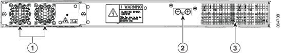
1 |
Fan tray |
3 |
Air vents |
|
2 |
Grounding lug |
— |
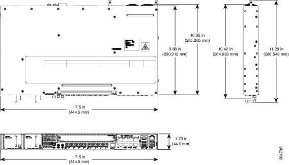
The following table describes the other features of Cisco ASR-920-12SZ-IM (AC and DC) Router.
|
Specification |
ASR-920-12SZ-IM |
|---|---|
|
DimensionWidth x Depth x Height |
17.5 x 9.88 x 1.73 inches |
|
Weight |
Total weight: 4.83 kg Weight of PSU: 0.59 kg Weight of Fan: 0.33 kg |
|
Rack Unit |
One RU |
|
Airflow |
Front to back |
|
Cable access |
Front cable access |
|
System throughput |
60 Gbps, 95 Mpps |
|
Power Supply |
|
|
Redundant |
Yes |
|
AC |
Yes |
|
Voltage Range |
85V AC to 264V AC, nominal 100/240 VAC |
|
Frequency Range |
47 Hz to 63 Hz, nominal 50/60 Hz |
|
Maximum Power |
360 W |
|
DC |
Yes |
|
Voltage Range |
-18 VDC to -32 VDC or -40 VDC to -72 VDC |
|
Nominal Voltage Range |
-24 VDC/-48 VDC/-60 VDC |
|
Maximum Power |
375 W |
|
Operating Temperature |
–40º C to 70º C |
|
Alarms |
|
|
Supported Interface Modules |
For more information on these IM modules, see the Cisco ASR 903 Aggregation Series Router Hardware Installation Guide. For more information on the supported IMs, see the Cisco ASR920 Data sheet. |
|
Mounting option |
|
|
Port Configuration |
12x1G and 4x10G/1G ports |
|
Port Numbering |
4x10G SFP+ – Port [12:15] 4x1G SFP – Port [8:11] 8x1G PoE RJ45/Cu ports [0:7] |
|
Combo Ports |
Ports 12 to 15 are Dual Rate ports |
|
Copper/1G/10G Port LEDs |
Link/Activity/Fault |
|
Temperature Sensors |
Four temperature sensors |
|
1PPS/ToD |
External ports for 1PPS/TOD |
|
PoE |
Provides power over Ethernet |
|
GNSS |
Connects to the external GPS |
External Interfaces
The external physical interfaces on the front panel of the router are:
-
Network Interfaces
-
Network Timing Interfaces
-
External Alarm Inputs
-
Management Interfaces
-
Mangement ENET Port
-
RS232 Console Port
-
USB Console
-
USB Mass Storage
-
Zero Touch Provisioning (ZTP)
-
RS232 Auxiliary Console Port
-
Power Supply
The router supports AC, DC, or a combination of both power supplies in a 1+1 redundant configuration. For information on installing the power supplies, see the Installing the Power Supply section.
Note |
If only one PSU is present, a successful firmware upgrade to either primary or secondary microcontroller unit (MCU) triggers a reload of device and is reloaded before any warning messages are displayed. |
|
Specification |
AC (A920-PWR400-A) |
DC (A920-PWR400-D) |
|---|---|---|
|
Input Voltage |
85–264, nominal 100VAC, 240VAC 47–63 Hz, nominal 50/60 Hz |
18–32 VD or -40 to -72 VDC Nominal - 24V VDC, or -48VDC, or -60VDC |
|
Maximum Input Power |
375W (with PoE power of 180W) 150W Max (No PoE) |
375W (with PoE power of 180W) 150W Max (No PoE |
|
Redundant |
Yes |
Yes |
|
How Swap |
Yes |
Yes |
|
Current sharing |
Yes |
Yes |
|
Input Connector |
IEC60320, C15 style receptacle |
Two-position terminal block |
Note |
This product requires surge protection as part of the building installation. To comply with the Telcordia GR-1089 NEBS standard for electromagnetic compatibility and safety, an external surge protective device (SPD) is required at the AC power service equipment. |
Note |
For DC systems, if a surge of more than 500 V is expected, add an appropriate external surge protective device. |
Note |
The routers support AC and DC power supplies in a 1+1 redundant configuration. One AC and one DC power supply in the same router is also a supported configuration. |
The router has a single fan-tray with four fans. The system is designed to operate at its maximum operating temperature of 70º C, in case of failure of a single fan operating temperature of 65º C. The fan tray is field-replaceable.
Licensing
The router supports the following types of licenses:
- Port Licensing—Port Upgrade
license is available as a "Pay as you Grow" model.
- 6 ports 1GE upgrade license
- 2 ports 10G upgrade license
- Bulk License to enable 12x1port 1GE and 4x10GE ports
- Advanced Metro IP Access
- Metro IP Access
- Metro Access (default)
- Feature licensing
The following methods are used to activate the above licenses:
- Cisco Software Licensing—The Cisco Software License Activation feature is a set of processes and components to activate Cisco software feature sets by obtaining and validating fee-based Cisco software licenses.
Note |
Licenses generated by the Cisco Software Licensing are tied to the UDI of the chassis and a corresponding watchtower device certificate (WDC) is stored in the system. |
- Cisco Smart Licensing—Smart Licensing is usage-based licensing where devices register with the Cisco Secure server.
Installing the Router in a Rack
Each Cisco ASR 920 Series Aggregation Services Router router includes rack-mounting brackets. Using the rack-mounting brackets, you can mount the router in a 19-inch, 23-inch, or an ETSI rack that conforms to the EIA-310-D specification.
Using the two rack-mounting brackets for mounting, you can recess the router in the equipment rack. This arrangement provides extra space in front of the router for the cables and allows you to close the doors of racks equipped with front-close doors.
To attach or replace the rack-mounting brackets, see the Attaching Brackets to the Router section.
The rack-mounting brackets are slotted to allow the router to be mounted in racks with EIA 1.25-inch (3.175-cm) or WECO 1.0-inch (2.54-cm) hole spacing. When installed in the rack, the router requires one EIA 1.75-inch (4.4-cm) vertical mounting space (or 1 rack unit [RU]) for mounting (see the Mounting the Router in a Rack section).
 Caution |
Allow clearance on either side of the router for cooling air to be drawn in through the right side and circulated through the chassis and out the three-fan exhaust ports mounted on the other side of chassis. |
The sections describe how to install the router in a rack. The procedures in this section apply to both horizontal and vertical mounting of the router in a rack:
Attaching Brackets to the Router
To attach the router on a 19-inch rack, use the 19-inch brackets (part number 700-39959-01).
Note |
The bracket mounting screws are pre-installed on the router. Depending on the bracket mounting position of the chassis, you must remove the appropriate screws, fix the bracket, and install the screws again. |
For more information on brackets, see the Cisco ASR-920-12SZ-IM and ASR-920U-12SZ-IM Aggregation Services Router Hardware Installation Guide.
Attaching Brackets for 19-Inch Racks
The following figure shows how to attach brackets for 19-inch racks on the router.
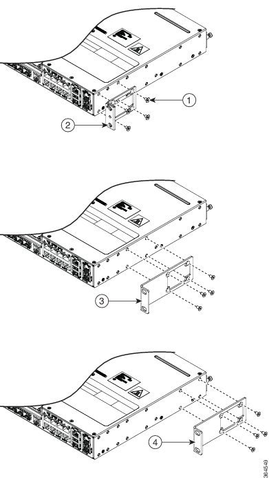
|
1 |
Phillips flat-head screws |
2 |
Front-mounting position |
|
3 |
Mid-mounting position |
4 |
Rear-mounting position |
Mounting the Router in a Rack
Perform the steps given below to mount the router into the equipment rack.
Note |
To secure the router to the equipment rack, you must use the two mounting screws (provided) for each side or follow your local practices for installing the router into your equipment rack. Ensure that the rack-mount brackets are securely fastened. For more information, see the Attaching Brackets to the Router section in the Cisco ASR-920-12SZ-IM and ASR-920U-12SZ-IM Aggregation Services Router Hardware Installation Guide. |
SUMMARY STEPS
- Locate the equipment rack position where you plan to install the router.
- Verify that there are no obstructions and ensure that the equipment rack is stabilized.
- Locate the mounting holes of the router.
- Align the rack-mounting bracket with the router and position with the four #6-32 x 0.25-inch screws (provided).
- Insert the screws (four places) and tighten using a Number 2 Phillips screwdriver (each side).
- Position the router in the equipment rack lining up the bracket holes on the router with the holes on the rack and secure with four #6-32 x 0.25-inch mounting screws (two on each side).
- Tighten the screws using a 1/4-inch flat-blade screwdriver (each side). The recommended maximum torque is 10 in.-lb.
DETAILED STEPS
| Step 1 |
Locate the equipment rack position where you plan to install the router. |
| Step 2 |
Verify that there are no obstructions and ensure that the equipment rack is stabilized. |
| Step 3 |
Locate the mounting holes of the router. |
| Step 4 |
Align the rack-mounting bracket with the router and position with the four #6-32 x 0.25-inch screws (provided). |
| Step 5 |
Insert the screws (four places) and tighten using a Number 2 Phillips screwdriver (each side). |
| Step 6 |
Position the router in the equipment rack lining up the bracket holes on the router with the holes on the rack and secure with four #6-32 x 0.25-inch mounting screws (two on each side). |
| Step 7 |
Tighten the screws using a 1/4-inch flat-blade screwdriver (each side). The recommended maximum torque is 10 in.-lb. |
Installing the Router Chassis in the Rack
Note |
Ensure adequate air flow when mounting the router in a rack. For more information, see the Air Flow Guidelines section in the Cisco ASR-920-12SZ-IM and ASR-920U-12SZ-IM Aggregation Services Router Hardware Installation Guide. |
Note |
Install the cable guides before installing the router in a 19-inch EIA rack. See the Attaching the Cable Guides section in the Cisco ASR-920-12SZ-IM and ASR-920U-12SZ-IM Aggregation Services Router Hardware Installation Guide. |
To install the router chassis in the equipment rack, perform these steps:
Procedure
| Step 1 |
Position the chassis in the rack as follows:
|
| Step 2 |
Align the mounting holes in the bracket (and optional cable guide) with the mounting holes in the equipment rack. The following figure shows how to install the router in a 19-inch EIA rack. 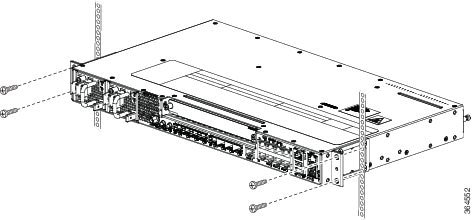 |
| Step 3 |
Install the four M6x12mm zinc-plated steel screws through the holes in the bracket and into the threaded holes in the equipment rack posts. |
| Step 4 |
Use a tape measure and level to verify that the chassis is installed straight and level. |
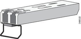
Installing SFP Modules
The following figure shows an SFP module that has a bale-clasp latch.
Caution |
We strongly recommend that you do not install or remove fiber-optic SFP modules with cables attached because of the potential
damage to the cables, the cable connector, or the optical interfaces in the SFP module. Disconnect all cables before removing
or installing an SFP module.Removing and installing an SFP module can shorten its useful life. Do not remove and insert SFP
modules more often than is absolutely necessary.
 |
To insert an SFP module into the module slot, follow these steps:
Procedure
| Step 1 |
Attach an ESD-preventive wrist strap to your wrist and to a bare metal surface on the chassis. Some SFP modules identify the top side of the module with send (TX) and receive (RX) markings or arrows that show the direction of the connection. |
||
| Step 2 |
If the SFP module that you are using has the markings, use them to identify the top side of the module. |
||
| Step 3 |
Align the SFP module in front of the slot opening. |
||
| Step 4 |
Insert the SFP module into the slot until you feel the connector on the module snap into place in the rear of the slot. 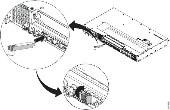
|
||
| Step 5 |
Insert the cable connector into the SFP module:
|
Installing the Chassis Ground Connection
Before you connect the power or turn on the power to the router, you must provide an adequate chassis ground (earth) connection to your router.
This section describes how to ground the chassis. The grounding lug location is on the back panel of the router.
 Tip |
Ensure that the grounding lug wire does not cover the fan opening. |
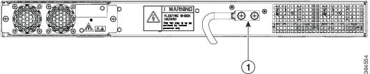
|
1 |
Grounding-lug |
To ensure that the chassis ground connection that you provide is adequate, you need the following parts and tools:
- Ratcheting torque screwdriver with Phillips head that exerts up to 15 in.-lb (1.69 N-m) of torque for attaching the ground wire to the router
- Crimping tool as specified by the ground lug manufacturer
- 6-AWG or larger copper wire for the ground wire
- Wire-stripping tools appropriate to the wire you are using
Caution |
Before making connections to the router, ensure that you disconnect the power at the circuit breaker. Otherwise, severe injury to you or damage to the router may occur. |
Caution |
Electric Shock Hazard: This fan tray has to be serviced by trained personnel only. |
 Warning |
This equipment must be grounded. Never defeat the ground conductor or operate the equipment in the absence of a suitably installed ground conductor. Contact the appropriate electrical inspection authority or an electrician if you are uncertain that suitable grounding is available. Statement 1024 |
Warning |
Use copper conductors only. Statement 1025 |
Warning |
When installing the unit, the ground connection must always be made first and disconnected last. Statement 42 |
This unit is to be installed in a restrictive access location and must be permanently grounded to a minimum 6-AWG copper ground wire.
Perform the following procedure to ground the router using a 2-hole lug and the corresponding mounting point. Most carriers require a minimum 6-AWG ground connection. Verify your carrier’s requirements for the ground connection.
Procedure
| Step 1 |
If your ground wire is insulated, use a wire-stripping tool to strip the ground wire to 0.5 inch ± 0.02 inch (12.7 mm ±0.5 mm). 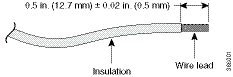 |
| Step 2 |
Slide the open end of your 2-hole ground lug over the exposed area of the ground wire. |
| Step 3 |
Using a crimping tool (as specified by the ground lug manufacturer), crimp the ground lug to the ground wire as shown in the following figure. 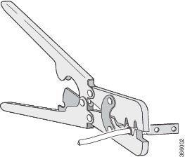 |
| Step 4 |
Use a Phillips head screwdriver to attach the 2-hole ground lug and wire assembly to the router with the 2 pan-head Phillips head screws. |
| Step 5 |
Connect the other end of the ground wire to a suitable grounding point at your site. |
Installing the Fan Tray
Follow these steps to install the fan tray in the chassis:
Caution |
Electric Shock Hazard: This fan tray has to be serviced by trained personnel only. |
Caution |
Always wear the ESD wrist strap when installing or uninstalling the fan tray. |
Caution |
Unplug all power sources before performing this procedure. |
Procedure
| Step 1 |
Orient the fan tray so that the captive screws are aligned to the chassis cavity on the back panel. See the following figure. 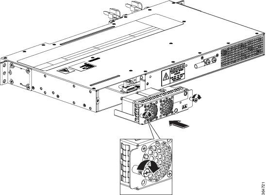 |
| Step 2 |
Push the fan assembly into the chassis until the power connector seats in the backplane and the captive installation screws make contact with the chassis. |
| Step 3 |
Tighten the captive installation screws, using a flat-blade or number 2 Phillips-head screwdriver. |
Installing an Interface Module
Caution |
Before inserting an interface module, make sure that the chassis is grounded. |
Procedure
| Step 1 |
To insert the interface module, carefully align the edges of the interface module between the upper and lower edges of the router slot. |
| Step 2 |
Carefully slide the interface module into the router slot until the interface module makes contact with the backplane. |
| Step 3 |
Tighten the locking thumbscrews on both sides of the interface module. The recommended maximum torque is 5.5 in.-lb (.62 N-m). |
| Step 4 |
Connect all the cables to each interface module. |
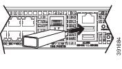
Installing the DC Power Supply Module
This equipment is suitable for installation in Network Telecommunications Facilities and locations where the NEC applies.
This equipment is suitable for installations utilizing the Common Bonding Network (CBN).
The grounding architecture of this product is DC-Isolated (DC-I) for DC-powered products. DC-powered products have a nominal operating DC voltage of 48 VDC.
Perform the following procedure to install the power supply module:
Procedure
| Step 1 |
Ensure that the system (earth) ground connection has been made. See the following figure. |
| Step 2 |
If necessary, remove the blank power supply filler plate from the chassis power supply bay opening by loosening the captive installation screws. |
| Step 3 |
Verify that power to the DC circuit connected to the power supply you are installing is off. To ensure that power has been removed from the DC circuits, locate the circuit breakers for the DC circuits, switch the circuit breakers to the OFF position, and tape the circuit-breaker switches in the OFF position. |
| Step 4 |
Grasp the power supply handle with one hand. Place your other hand underneath the power supply. Slide the power supply into the power supply bay. Make sure that the power supply is fully seated in the bay. |
| Step 5 |
Tighten the captive installation screws of the power supply. The recommended maximum torque is 5.5 in.-lb (0.62 N-m).  |
Activate a DC Power Supply Module
Perform the following procedure to activate a DC power supply:
Procedure
| Step 1 |
Remove the tape from the circuit-breaker router handle, and restore power by moving the circuit-breaker router handle to the On (|) position. |
||
| Step 2 |
Verify power supply operation by checking if the respective power supply front panel LED (PS0 or PS1) is green. |
||
| Step 3 |
If the LEDs indicate a power problem, see Troubleshooting. |
||
| Step 4 |
If you are connecting a redundant DC power supply, repeat these steps for the second power source.
|
Install the AC Power Cables
To install the AC power cables in the power supply slots:
Procedure
| Step 1 |
Plug the power supply cord in the power supply module. |
||
| Step 2 |
Insert the power supply cord into the tie [1,3] and tighten the tie around the power supply cord as shown in [2,4] in the figure below. 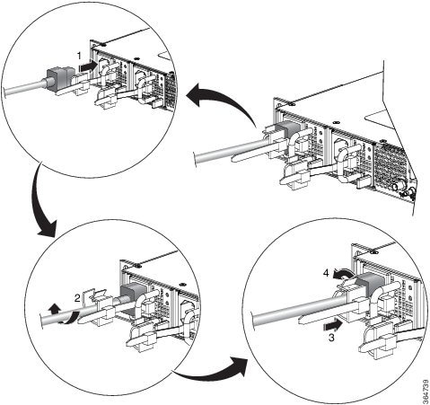
|
Activate an AC Power Supply Module
Perform the following procedure to activate an AC power supply:
Procedure
| Step 1 |
Plug the power cord into the power supply. |
||
| Step 2 |
Connect the other end of the power cord to an AC-input power source. |
||
| Step 3 |
Verify power supply operation by checking if the respective power supply front panel LED (PS0 or PS1) is green. |
||
| Step 4 |
If the LEDs indicate a power problem, see Troubleshooting for troubleshooting information. |
||
| Step 5 |
If you are connecting a redundant AC power supply, repeat these steps for the second power source.
|
Connecting Console Cables
The sections describe how to connect to the router using console cables:
Connecting to the USB Serial Port Using Microsoft Windows
This procedure shows how to connect to the USB serial port using Microsoft Windows.
Note |
Install the USB device driver before establishing a physical connection between the router and the PC, by using the USB console cable plugged into the USB serial port. Otherwise, the connection will fail. For more information, see the Installing the Cisco USB Device Driver section in the Cisco ASR-920-12SZ-IM and ASR-920U-12SZ-IM Aggregation Services Router Hardware Installation Guide. |
Procedure
| Step 1 |
Connect a USB Type A-to-Type A cable to the USB console port. If you are using the USB serial port for the first time on a Windows-based PC, install the USB driver now according to the instructions in the following sections:
|
||
| Step 2 |
Connect the USB Type A cable to the PC. |
||
| Step 3 |
To communicate with the router, start a terminal emulator application, such as Microsoft Windows HyperTerminal. This software should be configured with the following parameters:
|
Connecting a USB Flash Device
To connect a USB flash device to the router, insert the memory stick in the USB port labeled USB MEM. The Flash memory module can be inserted only one way, and can be inserted or removed regardless of whether the router is powered up or not.
Configuring the Router at Startup
This section explains how to create a basic running configuration for your router.
Note |
You must acquire the correct network addresses from your system administrator or consult your network plan to determine the correct addresses before you can complete the router configuration. |
Before continuing the configuration process, check the current state of the router by entering the show version command. This command displays the release of Cisco IOS software that is available on the router.
For information on modifying the configuration after you create it, see the Cisco IOS configuration and Cisco IOS Master Command List, All Releases guides.
To configure a Cisco ASR 920 Series Router from the console, you must connect a terminal or terminal server to the console port on the Cisco ASR 920 Series Router. To configure the router using the management Ethernet port, you must have the router’s IP address.
Accessing the CLI Using the Console
To access the command line interface using the console, follow these steps:
Procedure
| Step 1 |
When your system is booting, type No at the prompt. Example: |
| Step 2 |
Press Return to enter the user EXEC mode. The following prompt is displayed: Example: |
| Step 3 |
From the user EXEC mode, enter the enable command, as shown in the following example: Example: |
| Step 4 |
At the password prompt, enter your system password, as shown in the following example. If an enable password has not been set on your system, you can skip this step. Example:When your password is accepted, the privileged EXEC mode prompt is displayed: Example:You now have access to the CLI in the privileged EXEC mode. You can enter the necessary commands to complete the required tasks. |
| Step 5 |
To exit the console session, enter the quit command, as shown in the following example: Example: |
Configuring Global Parameters
When you first start the setup program, configure the global parameters. These parameters are used for controlling system-wide settings. Perform the following steps to enter the global parameters:
Procedure
| Step 1 |
Connect a console terminal to the console port, and then boot the router. For more information on connecting a console terminal, see Connecting Console Cables section. |
| Step 2 |
The first sections of the configuration script appear only at an initial system startup. On subsequent uses of the setup facility, the script begins with a System Configuration Dialog as shown below: When you are prompted about whether you want to enter the initial configuration dialog, enter yes. Example:Basic management setup configures enough connectivity for managing the system; extended setup will ask you to configure each interface on the system. |
Checking the Running Configuration Settings
To check the value of the settings you have entered, enter the show running-config command at the Router# prompt:
Router# show running-config
To review the changes you have made to the configuration use the show startup-config command in the user EXEC mode to see the changes and copy run-start stored in the NVRAM.
Saving the Running Configuration to NVRAM
To store the configuration or changes to your startup configuration in NVRAM, enter the copy running-config startup-config command at the prompt:
Router# copy running-config startup-config
Using this command saves the configuration settings that you created in the router using the configuration mode and the setup facility. If you fail to do this, your configuration will be lost, and will not be available when you reload the router next.
Safely Powering Off the Router
This section explains how to shut down the router. We recommend that before turning off all power to the chassis, you issue the reload command. This ensures that the operating system cleans up all the file systems. After the reload operation is complete, the router can be powered off safely.
To power off the router safely,:
Procedure
| Step 1 |
Slip on the ESD-preventive wrist strap included in the accessory kit. |
||
| Step 2 |
Enter the reload command. |
||
| Step 3 |
Confirm the reload command. Example: |
||
| Step 4 |
After confirming the reload command, wait until the system bootstrap message is displayed before powering off the system: Example: |
||
| Step 5 |
Remove power cables, if any, from the Cisco ASR 920-24SZ-IM, ASR-920-24SZ-M, ASR-920-24TZ-M Router:
|
Related Documents
-
Cisco ASR 920 and ASR 920U Aggregation Services Router Hardware Installation Guide can be viewed at: https://www.cisco.com/c/en/us/td/docs/routers/asr920/hardware/installation/guide-12sz-im/b-asr-920-12-SZ-IM.html.
-
The documentation for the supported software features can be viewed at https://www.cisco.com/c/en/us/support/routers/asr-920-series-aggregation-services-router/products-installation-and-configuration-guides-list.html.
 Feedback