Configuring Serial Interfaces

This chapter configures the serial interface module (PN: A900-IMASER14A/S) Async/Sync R232 serial data using Transparent Pseudowire (PW) over MPLS network and raw socket. It includes the following sections:

For information about managing your system images and configuration files, refer to the Cisco IOS Configuration Fundamentals Configuration Guide and Cisco IOS Configuration Fundamentals Command Reference publications.

For more information about the commands used in this chapter, refer to the Cisco IOS Command Reference publication for your Cisco IOS software release.

Information About Serial Interface Module

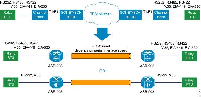
The serial interface module supports pseudowire transport over MPLS and raw socket for Async and Sync tranffic. The Serial IM interfaces monitor and detect cable connections, cable types and also monitors modem control signals periodically.

Figure 1. Pseudowire Transport for Serial Interface

The A900-IMASER14A/S interface provides a direct connection between the Cisco ASR 920router and external networks.


Note

We recommend that you use a smart serial or 4-port octopus cable to connect the A900-IMASER14A/S with the external network.

Out of 14 ports, 6 ports support sync interfaces and 8 ports support async interfaces. RS232 Async data is carried over Raw Socket and Transparent byte mode and RS232 Sync data is carried over Raw Socket.

Restrictions

This section describes the port restrictions for Serial interface module:

  • Ports 0-7 are Async ports on the 68-pin connector

  • Ports 8-13 are Sync or Async on the 12-in-1 connector


Note

Sync is not supported in Cisco IOS XE Release 3.14S. Sync ports cannot be configured in Cisco IOS XE Release 3.14S.


  • Maximum speed on all ports is 236Kbps.

This section describes the software limitations that apply when configuring the Serial interface module:

  • The router can only be configured as data circuit-terminating equipment (DCE).

  • Configuration of pseudowire between local and remote PE with different speed on Sync and Async ports is not supported.

  • Sub-rate (below DS0 bandwidth) Async (R232) data over MPLS MPLS using T1/E1 CESoP is not supported.

  • Pseudowire ping is not supported for the pseusdowire configured on the serial interface module.

  • Only two serial interface modules can come up on the router in release prior to Cisco IOS XE Release 3.14. Starting with Cisco IOS XE Release 3.14, all 6 bays on the router are available for insertion of interface modules simultaneously.

  • Only Trans encapsulation is supported in Cisco IOS XE Release 3.14S.

  • If you installed a new A900-IMASER14A/S or if you want to change the configuration of an existing interface, you must enter configuration mode to configure the new interfaces. If you replaced an A900-IMASER14A/S that was previously configured, the system recognizes the new interfaces and brings each of them up in their existing configuration.

  • Pseudowire ping is not supported for cross-connect configured on A900-IMA14A/S interface module.

  • A maximum speed of 64 kbps between PE and DTE is supported for RS232 Sync ports.

  • PE can act only as DCE and provides the clock to DTE.

  • Serial IM Sync signaling transport does not interoperate with the third party equipments. HLDC frames used for transport of these signals are Cisco-specific.

  • CTS signal goes down, when control signal frequency is configured more than 5000 ms and timeout setting is more than 20,000 ms (4x control_frequency), which is greater than the OIR time (~20s) for a selected subordinate to complete an OIR cycle. This results in the primary being unaware that the subordinate is down and CTS of all subordinates are down too. To avoid this situation, ensure that the timeout is shorter than the OIR time of the subordinate. Set the control frequency to less than or equal to 5000 ms and the timeout setting to less than or equal to 20,000 ms before you perform OIR.

  • RS422 and RS485 can be configured only on ports 0-7 of the serial interface.

  • If the mode is changed from P2P to P2MP with one primary serving three subordinates (all three subordinates on the same card on another chassis, different from the primary) or an online insertion and removal (OIR) of the card is performed with P2MP configuration, CTS signal for all the subordinates will go down despite that all are still driving their RTS up. This will get corrected when the subordinates toggle their RTS.

How to Configure Serial Interface

Required Configuration Tasks

Configuring the Controller

To create the interfaces for the Serial interface module, complete these steps:

Procedure
  Command or Action Purpose
Step 1

configure terminal

Example:

Router# configure terminal 

Enters global configuration mode.

Step 2

controller serial slot/subslot/port

Example:

Router(config)# controller serial  0/4/1

Selects the controller to configure and enters controller configuration mode.

  • slot/subslot/port —Specifies the location of the interface.

Note 
The slot number is always 0.
Step 3

physical-layer async | sync

Example:

Router(config-controller)# physical-layer async

Configures the serial interface in async or sync mode.

  • async—Specifies async interface.

  • sync—Specifies sync interface. This is the default mode.

Step 4

exit

Example:

Router(config)# exit 

Exits configuration mode and returns to the EXEC command interpreter prompt.

Example: Controller Configuration

Router# configure terminal
Router(config)# controller 
0/4/1
Router(config-controller)# physical-layer async
Router(config)# exit

Optional Configurations

Configuring Layer 1 on Sync and Async Interface Server

The RS232 which is enabled by default on the async interface, supports RS232 DCE cable with the DB-25 connector. The Cisco smart serial cable with the DB-25 connector supports RS232, RS485, and RS422. The RJ45 cable type supports only RS485.

Procedure

Step 1

configure terminal

Example:

Router# configure terminal 

Enters global configuration mode.

Step 2

line slot/bay/port

Example:

Router(config)#line 0/4/1 

Select the controller to configure and enters serial interface configuration mode.

  • slot/subslot/port —Specifies the location of the interface.

Step 3

media-type { rs422 | rs485 }

Example:

Router(config-line)# media-type rs422

Sets the media type to either RS422 or RS485.

Step 4

databits { 5 | 6 | 7 | 8 }

Example:

Router(config-line)# databits 8

Sets the databit configuration. The default is 8.

Step 5

stopbits {1 | 1.5 | 2}

Example:

Router(config-line)# stopbits 2

Sets the stopbit configuration. The default is 2.

Step 6

speed speed-value

Example:

Router(config-line)# speed 9600

Specifies the serial interface speed. The valid range is form 300 to 230400. The default is 9600.

Step 7

raw-socket tcp server port server ip address

Example:
Router(config-line)# raw-socket tcp server 5000 1.1.1.1

Specifies raw-tcp server configuration.

Step 8

raw-socket packet length packet length

Example:
Router(config-line)# raw-socket packet-length 32

Specifies raw-tcp packet length configuration options.

Step 9

parity {even | mark | none | odd | space }

Example:

Router(config-line)# parity none

Sets the parity.

Step 10

sig-transport u-frame pattern pattern

Example:
Router(config-line)#sig-transport u-frame pattern NR0

This step is specific to Sync mode only. Specifies the u-frame format used for internal signal transport.

Step 11

control-sig-transport [on | off] frequency frequency range

Example:
Router(config-line)#control-sig-transport on frequency <50-65535>

Specifies if hardware control signals need to be sent to remote PE or not. Also specifies the frequency (period between successive control frames) in milliseconds. By default, control signal is OFF. Frequency needs to be configured only if the control signal is ON.

Step 12

connection-topology [point-to-point | point-to-multipoint]

Example:
Router(config-line)#connection-topology point-to-multipoint

This step is specific to Sync mode only. Specifies the type of topology.

Step 13

dtr [used | not-used]

Example:
 Router(config-line)# dtr not-used

(Optional) DTR is programmable when DTR pin in FPGA is not connected. By default, DTR is set as used.

Step 14

connection-timeout timeout

Example:
Router(config-line)# connection-timeout <800-65535>

(Optional) Specifies the connection timeout of the primary and subordinate session. It should be configured 4 times higher than the frequency.

Step 15

exit

Example:

Router(config)# exit 

Exits configuration mode and returns to the EXEC command interpreter prompt.


Example: Async Layer 1 Parameters

Router# configure terminal
Router(config)# line 0/4/1
Router(config-line)# databits 8
Router(config-line)# stopbits 2
Router(config-line)# speed 9600
Router(config-line)# parity none
Router(config-line)# exit

Configuring Layer 1 on Sync and Async Interface Client

Procedure

Step 1

configure terminal

Example:

Router# configure terminal 

Enters global configuration mode.

Step 2

line slot/bay/port

Example:

Router(config)# line 0/ 4/1 

Select the controller to configure and enters serial interface configuration mode.

  • slot/subslot/port —Specifies the location of the interface.

Step 3

databits { 5 | 6 | 7 | 8 }

Example:

Router(config-line)# databits 8
Example:

Sets the databit configuration. The default is 8.

Step 4

stopbits {1 | 1.5 | 2}

Example:

Router(config-line)# stopbits 2

Sets the stopbit configuration. The default is 2.

Step 5

speed speed-value

Example:

Router(config-line)# speed 9600

Specifies the serial interface speed. The valid range is form 300 to 230400. The default is 9600.

Step 6

raw-socket tcp client server ip address server port client ip address client port

Example:
Router(config-line)# raw-socket tcp client 1.1.1.1 5000 10.10.10.10 9000

Specifies raw-tcp client configuration.

Step 7

raw-socket packet length packet length

Example:
Router(config-line)# raw-socket packet-length 32

Specifies raw-tcp packet length configuration options.

Step 8

parity {even | mark | none | odd | space }

Example:

Router(config-line)# parity none

Sets the parity.

Step 9

exit

Example:

Router(config)# exit 

Exits configuration mode and returns to the EXEC command interpreter prompt.


Configuring a Channel Group

Procedure
  Command or Action Purpose
Step 1

configure terminal

Example:

Router# configure terminal 

Enters global configuration mode.

Step 2

controller serial slot/bay/port

Example:

Router(config)# controller serial 0/4/1 

Configures the controller.

slot/subslot/port —Specifies the location of the interface.

Step 3

channel-group channel-group

Example:

Router(config-controller)# channel-group 0 

Configures the channel group with specified NxDS0 time slots.

Step 4

exit

Example:

Router(config-controller)# exit 

Exits configuration mode and returns to the EXEC command interpreter prompt.

Example: Channel Group

Router# configure terminal
Router(config)# controller serial 0/4/1
Router(config-controller)# channel-group 0
Router(config-controller)# exit

Configuring Encapsulation

When traffic crosses a WAN link, the connection needs a Layer 2 protocol to encapsulate traffic.

Procedure
  Command or Action Purpose
Step 1

configure terminal

Example:

Router# configure terminal 

Enters global configuration mode.

Step 2

interface serial slot/bay/port

Example:

Router(config)# interface serial 0/ 4/1 

Selects the interface to configure from global configuration mode.

  • slot/subslot/port —Specifies the location of the interface.
Step 3

encapsulation { ppp |raw-tcp | trans | sdmc }

Example:

Router(config-if)# encapsulation raw-tcp

Set the encapsulation method on the interface.

  • ppp —Described in RFC 1661, PPP encapsulates network layer protocol information over point-to-point links.
  • trans —Transparent encapsulation.
Note 
Trans encapsulation is supported on the access side for serial interfaces which has cross connect configured.
  • sdmc —Switched Multimegabit Data Services (SDMC) for serial interface.
Step 4

exit

Example:

Router(config)# exit 

Exits configuration mode and returns to the EXEC command interpreter prompt.

Example: Encapsulation

Router# configure terminal
Router(config)# interface serial 0/
4/1
Router(config-if)# encapsulation trans
Router(config-if)# exit

Configuring Transparent Pseudowire (PW) Cross-Connect

Transparent PW mode provides a facility to configure the speed between 300 bps to 230400 bps.

Procedure
  Command or Action Purpose
Step 1

configure terminal

Example:

Router# configure terminal 

Enters global configuration mode.

Step 2

interface serial slot/bay/port

Example:

Router(config)# interface serial 0/ 4/1 

Selects the interface to configure from global configuration mode.

  • slot/subslot/port —Specifies the location of the interface.
Step 3

xconnect peer-router-id vcid encapsulation mpls

Example:

Router(config-if)# xconnect 1.1.1.1 1001 encapsulation mpls 

Configures the VC to transport packets.

Step 4

exit

Example:

Router(config)# exit 

Exits configuration mode and returns to the EXEC command interpreter prompt.

Example: Transparent Pseudowire on Cross Connect

Router# configure terminal
Router(config)# interface serial 0/
4/1
Router(config-if)# xconnect 1.1.1.1 1001 encapsulation mpls
Router(config)# exit

Configuring Invert Clock Signal

Procedure
  Command or Action Purpose
Step 1

configure terminal

Example:

Router# configure terminal 

Enters global configuration mode.

Step 2

controller serial slot/bay/port

Example:

Router(config)# controller serial 0/4/1 

Configures the controller.

slot/subslot/port —Specifies the location of the interface.

Step 3

invert data

Example:

Router(config-controller)# invert data 

Configures the invert data clock signal.

Step 4

exit

Example:

Router(config)# exit 

Exits configuration mode and returns to the EXEC command interpreter prompt.

Example: Invert Data on the Serial Interface

The following example shows invert data configuration on the serial interface.


Router# configure terminal
Router(config)# controller serial 0/4/1
Router(config-controller)# invert data
Router(config-controller)# exit

Configuring NRZI Formats

Procedure
  Command or Action Purpose
Step 1

configure terminal

Example:

Router# configure terminal 

Enters global configuration mode.

Step 2

interfaceserial slot/bay/port

Example:

Router(config)# interface serial 0/4/1 

Select the controller to configure and enters serial interface configuration mode.

  • slot/subslot/port —Specifies the location of the interface.
Step 3

nrzi-encoding

Example:
Router(config-if)# nrzi-encoding

Enable NRZI encoding.

To disable NRZI encoding, use the no form of the commnad.

Verifying the Serial Interface Configuration

Use the following commands to verify the configuration the serial interface

  • show controllers serial slot/bay/port

Use the show controllers serial slot/bay/port command to display serial interface configuration on the router.


Router# show controllers serial 0/1/0
Serial0/1/0 - (A900-IMASER14A/S) is up
 Encapsulation : RAW-TCP
Cable type: RS-232 DCE
mtu 1500, max_buffer_size 1524, max_pak_size 1524 enc 84
loopback: Off,  crc: 16, invert_data: Off
nrzi: Off, idle char: Flag
dce_terminal_timing_enable: Off ignore_dtr: Off
serial_clockrate: 64000bps, serial_clock_index: 14 serial_restartdelay:30000,  serial_restartdelay_def:30000

     DCD=up  DSR=up  DTR=up  RTS=up  CTS=up
  • show interfaces serial slot/bay/port

Use the show interfaces serial slot/bay/port command to display serial interface packet status information, model control signal status information on the router.


Router# show interfaces serial 0/1/0
Serial0/1/0 is up, line protocol is up
    Hardware is A900-IMASER14A/S
  MTU 1500 bytes, BW 64 Kbit/sec, DLY 20000 usec, 
     reliability 255/255, txload 47/255, rxload 103/255
  Encapsulation RAW-TCP, loopback not set
  Keepalive not supported 
  Last input never, output 00:00:00, output hang never
  Last clearing of "show interface" counters 00:38:06
  Input queue: 0/375/0/0 (size/max/drops/flushes); Total output drops: 0
  Queueing strategy: fifo
  Output queue: 0/40 (size/max)
  5 minute input rate 26000 bits/sec, 69 packets/sec
  5 minute output rate 12000 bits/sec, 69 packets/sec
     157782 packets input, 7562229 bytes, 0 no buffer
     Received 0 broadcasts (0 IP multicasts)
     0 runts, 0 giants, 0 throttles 
     0 input errors, 0 CRC, 0 frame, 0 overrun, 0 ignored, 0 abort
     156862 packets output, 3460471 bytes, 0 underruns
     0 output errors, 0 collisions, 0 interface resets
     0 unknown protocol drops
     0 output buffer failures, 0 output buffers swapped out
     0 carrier transitions
     DCD=up  DSR=up  DTR=up  RTS=up  CTS=up

  • show running-config interface serial slot/bay/port

Use the show running-config interface serial slot/bay/port command to display serial interface IP address information, keep alive and cross-connect status information on the router.


Router# show running-config interface serial 0/1/0
Building configuration...
Current configuration : 107 bytes
!
interface Serial0/1/0
 no ip address
 encapsulation trans
 xconnect 1.1.1.1 1001 encapsulation mpls
End
  • show xconnet all

Use the show xconnect all to command to display all cross connect status on the router.


Router# show xconnect all
Legend:    XC ST=Xconnect State  S1=Segment1 State  S2=Segment2 State
  UP=Up       DN=Down            AD=Admin Down      IA=Inactive
  SB=Standby  HS=Hot Standby     RV=Recovering      NH=No Hardware
XC ST  Segment 1                         S1 Segment 2                         S2
------+---------------------------------+--+---------------------------------+--
UP pri   ac Se0/1/0(HDLC)                UP mpls 1.1.1.1:1001                 UP

Use the show raw-socket tcp sessions and show raw-socket tcp statistic commands to display the raw socket status.


Router#show raw-socket tcp sessions 
-------------------------------------------------- TCP Sessions ------------------------------------------------------
Interface tty             vrf_name             socket  mode    local_ip_addr  local_port   dest_ip_addr  dest_port    up_time     idle_time/timeout
  0/3/12  154                                     0  server     20.20.20.20      5000        listening     ----        -----              -----
  0/3/12  154                                     1  server     20.20.20.20      5000      10.10.10.10     9000     00:20:49      00:00:00/5  min


Router#show raw-socket tcp statistic 
-------------------------------------------- TCP-Serial Statistics -----------------------------------------
Interface  tty             vrf_name             sessions      tcp_in_bytes         tcp_out_bytes   tcp_to_tty_frames    tty_to_tcp_frames
   0/3/12  154                                       1             1847204              4640310               87709                87671
Configuration Examples

This section includes the following configuration examples:

Example: Encapsulation Configuration

The following example sets encapsulation for the controller and interface:

PE1 CONFIG


controller SERIAL 0/1/0
 physical-layer async
 channel-group 0
interface Serial0/1/0
 no ip address
 encapsulation trans
 xconnect 2.2.2.2 1001 encapsulation mpls

PE2 CONFIG


controller SERIAL 0/2/0
 physical-layer async
 channel-group 0
interface Serial0/2/0
 no ip address
 encapsulation trans
 xconnect 1.1.1.1 1001 encapsulation mpls