- Using Cisco IOS XE Software
- Console Port Telnet and SSH Handling
- Configuring the Route Switch Processor
- Configuring Clocking and Timing
- G.8275.1 Telecom Profile
- Configuring the Global Navigation Satellite System
- Configuring Ethernet Interfaces
- Using the Management Ethernet Interface
- Configuring T1/E1 Interfaces
- Configuring Optical Interface Modules
- Configuring Serial Interfaces
- Enabling Support for Tunable DWDM-XFP-C
- Dying Gasp Support for Loss of Power Supply via SNMP, Syslog and Ethernet OAM
- Configuring Pseudowire
- Digital Optical Monitoring for Transceivers
- Configuring Synchronous Ethernet ESMC and SSM
- Configuring the SDM Template
- Tracing and Trace Management
- Configuring and Monitoring Alarm
- OTN Wrapper Overview
- Configuring 1G Traffic on 8-port 10 Gigabit Ethernet Interface Module
- Configuring Access Circuit Redundancy
- Index
- Advantages of OTN
- ODU and OTU
- OTU1e and OTU 2e Support on 8x10GE Interface Module
- Deriving OTU1e and OTU2e Rates
- OTU3 Support in 2x40GE Interface Module
- OTN Specific Functions
- Standard MIBS
- Restrictions for OTN
- DWDM Provisioning
- Configuring Transport Mode in 8x10GE and 2x40GE Interface Modules
- OTN Alarms
OTN Wrapper
Overview
Optical Transport Network (OTN) Wrapper feature provides robust transport services that leverage many of the benefits such as resiliency and performance monitoring, while adding enhanced multi-rate capabilities in support of packet traffic, plus the transparency required by Dense Wavelength Division Multiplexing (DWDM) networks. OTN is the ideal technology to bridge the gap between next generation IP and legacy Time Division Multiplexing (TDM) networks by acting as a converged transport layer for newer packet-based and existing TDM services. OTN is defined in ITU G.709 and allows network operators to converge networks through seamless transport of the numerous types of legacy protocols, while providing the flexibility required to support future client protocols.
OTN Wrapper feature is supported on the following interface modules:
The chassis acts as an aggregator for ethernet, TDM, and SONET traffic to connect to an OTN network and vice versa. The ports on the interface modules are capable of OTN functionality. The OTN controller mode enables the IPoDWDM technology in the interface modules. The OTN Wrapper encapsulates 10G LAN and 40G LAN into the corresponding OTU1e or OTU2e and OTU3 containers, respectively. This enables the ports of the interface modules to work in layer 1 optical mode in conformance with standard G.709.
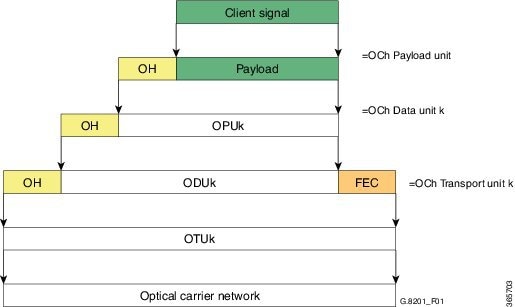
OTN Frame
The key sections of the OTN frame are the Optical Channel Transport Unit (OTU) overhead section, Optical Channel Data Unit (ODU) overhead section, Optical Channel Payload Unit (OPU) overhead section, OPU payload section, and Forward Error Correction (FEC) overhead section . The network routes these OTN frames across the network in a connection-oriented way. The Overhead carries the information required to identify, control and manage the payload, which maintains the deterministic quality. The Payload is simply the data transported across the network, while the FEC corrects errors when they arrive at the receiver. The number of correctable errors depends on the FEC type.
- Advantages of OTN
- ODU and OTU
- OTU1e and OTU 2e Support on 8x10GE Interface Module
- Deriving OTU1e and OTU2e Rates
- OTU3 Support in 2x40GE Interface Module
- OTN Specific Functions
- Standard MIBS
- Restrictions for OTN
- DWDM Provisioning
- Configuring Transport Mode in 8x10GE and 2x40GE Interface Modules
- OTN Alarms
- OTN Threshold
- Configuring OTU Alerts
- Configuring ODU Alerts
- Configuring ODU Alerts
- Loopback
- Configuring Loopback
- Forward Error Connection
- SNMP Support
- Performance Monitoring
- Troubleshooting Scenarios
- Associated Commands
Advantages of OTN
The following are the advantages of OTN:
-
Provides multi-layer performance monitoring and enhanced maintenance capability for signals traversing multi-operator networks.
-
Allows Forward Error Correction (FEC) to improve the system performance.
-
Provides enhanced alarm handling capability.
- Insulates the network against uncertain service mix by providing transparent native transport of signals encapsulating all client-management information.
-
Performs multiplexing for optimum capacity utilization, thereby improving network efficiency.
-
Enables network scalability as well as support for dedicated Ethernet services with service definitions.
ODU and OTU
Optical Channel Transport Unit (OTU) and Optical Channel Data Unit (ODU) are the two digital layer networks. All client signals are mapped into the optical channel via the ODU and OTU layer networks.
OTU
The OTU section is composed of two main sections: the Frame Alignment section, and the Section Monitoring (SM) section. The OTU Overhead (OH) provides the error detection correction as well as section-layer connection and monitoring functions on the section span. The OTU OH also includes framing bytes, enabling receivers to identify frame boundaries. For more information, see G.709 document.
ODU
The ODU section is an internal element allowing mapping or switching between different rates, which is important in allowing operators the ability to understand how the end user pipe is transferred through to the higher network rates. The ODU OH contains path overhead bytes allowing the ability to monitor the performance, fault type and location, generic communication, and six levels of channel protection based on Tandem Connection Monitoring (TCM). For more information, see G.709 document.
OTU1e and OTU 2e Support on 8x10GE Interface Module
The OTU1e and OTU2e are mapping mechanisms to map a client 10G Base-R signal to OTN frames transparently as per ITU-T G series Supplement 43 specification. Both these modes are over-clocked OTN modes. These mechanisms provide real bit transparency of 10 GbE LAN signals and are useful for deployment of 10G services.
The OTU1e and OTU2e are inherently intra-domain interfaces (IaDI) and are generally applicable only to a single vendor island within an operator's network to enable the use of unique optical technology. The OTU1e and OTU2e are not standard G.709 bit-rate signals and they do not interwork with the standard mappings of Ethernet using GFP-F. These two over-clocked mechanisms do not interwork with each other. As a result, such signals are only deployed in a point-to-point configuration between equipment that implements the same mapping.
The 10GBase-R client signal with fixed stuff bytes is accommodated into an OPU-like signal, then into an ODU-like signal, and further into an OTU-like signal. These signals are denoted as OPU2e, ODU2e and OTU2e, respectively . The OTU1e does not add 16 columns of fixed stuff bytes and hence overall data rate is relatively lesser at 11.0491 Gbps as compared to OTU2e which is 11.0957 Gbps.
The following table shows the standard OTU rates:
|
G.709 Interface |
Line Rate |
Corresponding Ethernet Rate |
Line Rate |
|---|---|---|---|
|
OTU-1e |
11.0491 Gbit/s without stuffing bits |
10 Gig E-LAN |
10.3125 Gbit/s |
|
OTU-2e |
11.0957 Gbit/s without stuffing bits |
10 Gig E-LAN |
10.3125 Gbit/s |
|
OTU-3 |
43.018 Gbit/s |
STM-256 or OC-768 |
39.813 Gbit/s |
Deriving OTU1e and OTU2e Rates
A standard OTN frame consists of 255 16-column blocks and the payload rate is 9953280 Kbit/s. This is because the overhead and stuffing in the OTN frames happen at a granularity of 16-column blocks. Thus, OPU payload occupies (3824-16)/16=238 blocks. The ODU occupies 239 blocks and the OTU (including FEC) occupies 255 blocks. Hence, the multiplication factor in the G.709 spec is specified using numbers like 237, 238, 255.
Since OPU2e uses 16 columns that are reserved for stuffing and also for payload, the effective OPU2e frequency is:
OTU3 Support in 2x40GE Interface Module
When 40GbE LAN is transported over OTN, there is no drop in line rate when the LAN client is mapped into the OPU3 using the standard CBR40G mapping procedure as specified in G.709 clause 17.2.3. The 40G Ethernet signal (41.25 Gbit/s) uses 64B/66B coding making it slightly larger than the OPU3 payload rate that is 40.15 Gbit/s. Hence, to transport 40G Ethernet service over ODU3, the 64B/66B blocks are transcoded into 1024B/1027B block code to reduce their size. The resulting 40.117 Gbit/s transcoded stream is then mapped in standard OPU3.
OTN Specific Functions
The following figure shows the OTN specific functions related to overhead processing, alarm handling, FEC and TTI:
Standard MIBS
The following are the standard MIBS:
Restrictions for OTN
The following are the restrictions for OTN:
DWDM Provisioning
All DWDM provisioning configurations take place on the controller. To configure a DWDM controller, use the controller dwdm command in global configuration mode.
Prerequisites for DWDM Provisioning
The g709 configuration commands can be used only when the controller is in the shutdown state. Use the no shutdown command after configuring the parameters, to remove the controller from shutdown state and to enable the controller to move to up state.
Configuring DWDM Provisioning
Use the following commands to configure DWDM provisioning:
enable
configure terminal
controller dwdm 0/1/0
Configuring Transport Mode in 8x10GE and 2x40GE Interface Modules
Use the transport-mode command in interface configuration mode to configure LAN and OTN transport modes in 8x10GE and 2x40GE interface modules. The transport-mode command otn option has the bit-transparent sub-option, using which bit transparent mapping into OPU1e or OPU2e can be configured.
Use the following commands to configure LAN and OTN transport modes:
enable
configure terminal
controller dwdm 0/0/0
transport-mode otn bit-transparent opu1e
 Note | LAN transport mode is the default mode. |
To configure the transport administration state on a DWDM port, use the admin-state command in DWDM configuration mode. To return the administration state from a DWDM port to the default, use the no form of this command.
- Verification of LAN Transport Mode Configuration
- Verification of OTN Transport Mode Configuration in 8x10GE Interface Modules
- Verification of OTN Transport Mode Configuration in 2x40GE Interface Modules
- Changing from OTN to LAN Mode
- Verification of Enabled Ports for Controller Configuration
Verification of LAN Transport Mode Configuration
Use the show interfaces command to verify the configuration of LAN transport mode:
Router#sh int te0/1/0
TenGigabitEthernet0/1/0 is up, line protocol is up
  MTU 1500 bytes, BW 10000000 Kbit/sec, DLY 10 usec,
     reliability 255/255, txload 8/255, rxload 193/255
  Encapsulation ARPA, loopback not set
  Keepalive set (10 sec)
  Full Duplex, 10000Mbps, link type is force-up, media type is SFP-SR
  output flow-control is unsupported, input flow-control is on
  Transport mode LAN
  ARP type: ARPA, ARP Timeout 04:00:00
  Last input 04:02:09, output 04:02:09, output hang never
  Last clearing of "show interface" counters 00:29:47
  Input queue: 0/375/0/0 (size/max/drops/flushes); Total output drops: 0
  Queueing strategy: fifo
  Output queue: 0/40 (size/max)
  5 minute input rate 7605807000 bits/sec, 14854906 packets/sec
  5 minute output rate 335510000 bits/sec, 655427 packets/sec
     26571883351 packets input, 1700600465344 bytes, 0 no buffer
     Received 0 broadcasts (0 IP multicasts)
     0 runts, 0 giants, 0 throttles
     0 input errors, 0 CRC, 0 frame, 0 overrun, 0 ignored
     0 watchdog, 0 multicast, 0 pause input
     10766634813 packets output, 689064271464 bytes, 0 underruns
     0 output errors, 0 collisions, 0 interface resets
     0 unknown protocol drops
     0 babbles, 0 late collision, 0 deferred
     0 lost carrier, 0 no carrier, 0 pause output
     0 output buffer failures, 0 output buffers swapped out
Router#
Verification of OTN Transport Mode Configuration in 8x10GE Interface Modules
Use the show interfaces command to verify the configuration of OTN transport mode in 8x10GE interface modules:
Router#sh int te0/1/1
TenGigabitEthernet0/1/1 is up, line protocol is up
  MTU 1500 bytes, BW 10000000 Kbit/sec, DLY 10 usec,
     reliability 255/255, txload 193/255, rxload 7/255
  Encapsulation ARPA, loopback not set
  Keepalive set (10 sec)
  Full Duplex, 10000Mbps, link type is force-up, media type is SFP-SR
  output flow-control is unsupported, input flow-control is on
  Transport mode OTN (10GBASE-R over OPU1e w/o fixed stuffing, 11.0491Gb/s)
  ARP type: ARPA, ARP Timeout 04:00:00
  Last input 03:28:14, output 03:28:14, output hang never
  Last clearing of "show interface" counters 00:30:47
  Input queue: 0/375/0/0 (size/max/drops/flushes); Total output drops: 0
  Queueing strategy: fifo
  Output queue: 0/40 (size/max)
  5 minute input rate 281326000 bits/sec, 549608 packets/sec
  5 minute output rate 7596663000 bits/sec, 14837094 packets/sec
     10766669034 packets input, 689066159324 bytes, 0 no buffer
     Received 0 broadcasts (0 IP multicasts)
     0 runts, 0 giants, 0 throttles
     0 input errors, 0 CRC, 0 frame, 0 overrun, 0 ignored
     0 watchdog, 0 multicast, 0 pause input
     27457291925 packets output, 1757266795328 bytes, 0 underruns
     0 output errors, 0 collisions, 0 interface resets
     0 unknown protocol drops
     0 babbles, 0 late collision, 0 deferred
     0 lost carrier, 0 no carrier, 0 pause output
     0 output buffer failures, 0 output buffers swapped out
Router#
Verification of OTN Transport Mode Configuration in 2x40GE Interface Modules
Use the show interfaces command to verify the configuration of OTN transport mode in 2x40GE interface modules:
Router#show int  fo0/4/0
FortyGigabitEthernet0/4/0 is up, line protocol is up
  MTU 1500 bytes, BW 40000000 Kbit/sec, DLY 10 usec,
     reliability 255/255, txload 1/255, rxload 1/255
  Encapsulation ARPA, loopback not set
  Keepalive set (10 sec)
  Full Duplex, 40000Mbps, link type is force-up, media type is QSFP_40GE_SR
  output flow-control is unsupported, input flow-control is on
  Transport mode OTN OTU3 (43.018Gb/s)
  ARP type: ARPA, ARP Timeout 04:00:00
  Last input never, output never, output hang never
  Last clearing of "show interface" counters never
  Input queue: 0/375/0/0 (size/max/drops/flushes); Total output drops: 0
  Queueing strategy: fifo
  Output queue: 0/40 (size/max)
  5 minute input rate 0 bits/sec, 0 packets/sec
  5 minute output rate 0 bits/sec, 0 packets/sec
     0 packets input, 0 bytes, 0 no buffer
     Received 0 broadcasts (0 IP multicasts)
     0 runts, 0 giants, 0 throttles
     0 input errors, 0 CRC, 0 frame, 0 overrun, 0 ignored
     0 watchdog, 0 multicast, 0 pause input
     0 packets output, 0 bytes, 0 underruns
     0 output errors, 0 collisions, 2 interface resets
     0 unknown protocol drops
     0 babbles, 0 late collision, 0 deferred
     0 lost carrier, 0 no carrier, 0 pause output
     0 output buffer failures, 0 output buffers swapped out
Changing from OTN to LAN Mode
Use the following methods to change from OTN mode to LAN mode:
Verification of Enabled Ports for Controller Configuration
Use the show controllers command to verify the enables ports for the controller configuration:
#show controllers
TenGigabitEthernet0/0/0
TenGigabitEthernet0/0/1
TenGigabitEthernet0/0/2
TenGigabitEthernet0/0/3
TenGigabitEthernet0/0/4
TenGigabitEthernet0/0/5
TenGigabitEthernet0/0/6
TenGigabitEthernet0/0/7
TenGigabitEthernet0/1/0
TenGigabitEthernet0/1/1
FortyGigabitEthernet0/4/0
FortyGigabitEthernet0/4/1
TenGigabitEthernet0/5/0
TenGigabitEthernet0/5/1
TenGigabitEthernet0/5/2
TenGigabitEthernet0/5/3
TenGigabitEthernet0/5/4
TenGigabitEthernet0/5/5
TenGigabitEthernet0/5/6
TenGigabitEthernet0/5/7
#
OTN Alarms
OTN supports alarms in each layer of encapsulation. All the alarms follow an alarm hierarchy and the highest level of alarm is asserted and presented as a Syslog message or on the CLI.
OTU Alarms
The types of alarms enabled for reporting:
-
AIS - Alarm indication signal (AIS) alarms
-
BDI - Backward defect indication (BDI) alarms
-
IAE - Incoming alignment error (IAE) alarms
-
LOF - Loss of frame (LOF) alarms
-
LOM - Loss of multiple frames (LOM) alarms
-
LOS - Loss of signal (LOS) alarms
-
TIM - Type identifier mismatch (TIM) alarms
-
SM - TCA - SM threshold crossing alert
-
SD-BER - SM BER is in excess of the SD BER threshold
-
SF-BER - SM BER is in excess of the SF BER threshold
ODU Alarms
The types of alarms enabled for reporting:
-
AIS - Alarm indication signal (AIS) alarms
-
BDI - Backward defect indication (BDI) alarms
-
LCK - Upstream connection locked (LCK) error status
-
OCI - Open connection indication (OCI) error status
-
PM-TCA - Performance monitoring (PM) threshold crossing alert (TCA)
-
PTIM - Payload TIM error status
-
SD-BER - SM BER is in excess of the SD BER threshold
-
SF-BER - SM BER is in excess of the SF BER threshold
-
TIM - Type identifier mismatch (TIM) alarms
Configuring OTN Alarm Reports
By default, all the OTN alarm reports are enabled. To control OTN alarm reports, disable all the alarms and enable the specific alarms.
Note | You need to shutdown the interface using the shut command to configure the alarms. |
Configuring OTU Alarm Reports
Use the following commands to configure OTU alarm reports:
enable
configure terminal
controller dwdm 0/4/1
shut
g709 otu report bdi
no shut
end
Note | Fecmismatch is not supported. |
Note | Use no g709 otu report command to disable the OTU alarm reports. |
Verification of OTU Alarm Reports Configuration
Use the show controllers command to verify OTU alarm reports configuration:
#show controllers dwdm 0/4/1
G709 Information:

Controller dwdm 0/4/1, is up (no shutdown)

Transport mode OTN OTU3
Loopback mode enabled : None

TAS state is : IS
G709 status : Enabled
( Alarms and Errors )
OTU
        LOS = 3           LOF = 1           LOM = 0
        AIS = 0           BDI = 0           BIP = 74444
        TIM = 0           IAE = 0           BEI = 37032

ODU
        AIS = 0           BDI = 0           TIM = 0
        OCI = 0           LCK = 0           PTIM = 0
        BIP = 2           BEI = 0

FEC Mode: FEC

Remote FEC Mode: Unknown
        FECM                            = 0
        EC(current second)              = 0
        EC                              = 186
        UC                              = 10695


Detected Alarms: NONE
Asserted Alarms: NONE
Detected Alerts: NONE
Asserted Alerts: NONE
Alarm reporting enabled for: LOS LOF LOM OTU-AIS OTU-IAE OTU-BDI ODU-AIS ODU-OCI ODU-LCK ODU-BDI ODU-PTIM ODU-BIP
Alert reporting enabled for: OTU-SD-BER OTU-SF-BER OTU-SM-TCA ODU-SD-BER ODU-SF-BER ODU-PM-TCA
BER thresholds: ODU-SF = 10e-3  ODU-SD = 10e-6  OTU-SF = 10e-3  OTU-SD = 10e-6
TCA thresholds: SM = 10e-3  PM = 10e-3

OTU TTI Sent     String SAPI ASCII      : Tx TTI Not Configured
OTU TTI Sent     String DAPI ASCII      : Tx TTI Not Configured
OTU TTI Sent     String OPERATOR ASCII  : Tx TTI Not Configured
OTU TTI Expected String SAPI ASCII      : Exp TTI Not Configured
OTU TTI Expected String DAPI ASCII      : Exp TTI Not Configured
OTU TTI Expected String OPERATOR ASCII  : Exp TTI Not Configured
OTU TTI Received String HEX  : 0000000000000000000000000000000000000000000000000
                               0000000000000000000000000000000000000000000000000
                               000000000000000000000000000000

ODU TTI Sent     String SAPI ASCII      : Tx TTI Not Configured
ODU TTI Sent     String DAPI ASCII      : Tx TTI Not Configured
ODU TTI Sent     String OPERATOR ASCII  : Tx TTI Not Configured
ODU TTI Expected String SAPI ASCII      : Exp TTI Not Configured
ODU TTI Expected String DAPI ASCII      : Exp TTI Not Configured
ODU TTI Expected String OPERATOR ASCII  : Exp TTI Not Configured
ODU TTI Received String HEX  : 0000000000000000000000000000000000000000000000000
                               0000000000000000000000000000000000000000000000000
                               000000000000000000000000000000
Syslog Generation for LOS Alarm
The following example shows the syslog generation for LOS alarm:
(config-if)#
*Jan 16 06:32:50.487 IST: %DWDM-4-G709ALARM: dwdm-0/4/1: LOS declared
*Jan 16 06:32:51.048 IST: %LINK-3-UPDOWN: Interface FortyGigabitEthernet0/4/1, changed state to down
*Jan 16 06:32:51.489 IST: %DWDM-4-G709ALARM: dwdm-0/4/1: LOF declared
*Jan 16 06:32:51.495 IST: %DWDM-4-G709ALARM: dwdm-0/4/1: LOS cleared
Configuring ODU Alarm Report
Use the following commands to configure ODU alarm reports:
enable
configure terminal
controller dwdm 0/4/1
shut
g709 odu report ais
no shut
end
Note | Use no g709 odu report command to disable the ODU alarm reports. |
OTN Threshold
The signal degrade and signal failure thresholds are configured for alerts.
The following types of thresholds are configured for alerts for OTU and ODU layers:
Configuring OTU Threshold
To configure OTU threshold:
enable
configure terminal
controller dwdm 0/4/1
shut
g709 otu threshold sm-tca 3
no shut
end
Note | Use no g709 otu threshold command to disable OTU threshold. |
Configuring ODU Threshold
To configure ODU threshold:
enable
configure terminal
controller dwdm 0/4/1
shut
g709 odu threshold sd-ber 3
no shut
end
Note | Use no g709 odu threshold command to disable configuration of ODU threshold. |
Verification of OTU and ODU Threshold Configuration
Use the show controllers command to verify OTU and ODU threshold configuration:
Router#show controllers dwdm 0/1/2
G709 Information:

Controller dwdm 0/1/2, is up (no shutdown)

Transport mode OTN (10GBASE-R over OPU1e w/o fixed stuffing, 11.0491Gb/s)
Loopback mode enabled : None

TAS state is : UNKNWN
G709 status : Enabled

OTU
        LOS = 0           LOF = 0           LOM = 0
        AIS = 0           BDI = 0           BIP = 0
        TIM = 0           IAE = 0           BEI = 0

ODU
        AIS = 0           BDI = 0           TIM = 0
        OCI = 0           LCK = 0           PTIM = 0
        BIP = 0           BEI = 0

FEC Mode: FEC

Remote FEC Mode: Unknown
        FECM                            = 0
        EC(current second)              = 0
        EC                              = 0
        UC                              = 0


Detected Alarms: NONE
Asserted Alarms: NONE
Detected Alerts: NONE
Asserted Alerts: NONE
Alarm reporting enabled for: LOS LOF LOM OTU-AIS OTU-IAE OTU-BDI OTU-TIM ODU-AIS ODU-OCI ODU-LCK ODU-BDI ODU-PTIM ODU-TIM ODU-BIP
Alert reporting enabled for: OTU-SD-BER OTU-SF-BER OTU-SM-TCA ODU-SD-BER ODU-SF-BER ODU-PM-TCA
BER thresholds: ODU-SF = 10e-3  ODU-SD = 10e-6  OTU-SF = 10e-3  OTU-SD = 10e-6
TCA thresholds: SM = 10e-3  PM = 10e-3

OTU TTI Sent     String SAPI ASCII      : AABBCCDD
OTU TTI Sent     String DAPI ASCII      : AABBCCDD
OTU TTI Sent     String OPERATOR ASCII  : AABBCCDD
OTU TTI Expected String SAPI ASCII      : AABBCCDD
OTU TTI Expected String DAPI ASCII      : AABBCCDD
OTU TTI Expected String OPERATOR HEX    : AABBCCDD
OTU TTI Received String HEX  : 0052414D4553480000000000000000000052414D455348000
                               0000000000000004141424243434444000000000000000000
                               000000000000000000000000000000

ODU TTI Sent     String SAPI ASCII      : AABBCCDD
ODU TTI Sent     String DAPI ASCII      : AABBCCDD
ODU TTI Sent     String OPERATOR HEX    : 11223344
ODU TTI Expected String SAPI ASCII      : AABBCCDD
ODU TTI Expected String DAPI ASCII      : AABBCCDD
ODU TTI Expected String OPERATOR HEX    : 11223344
ODU TTI Received String HEX  : 0052414D4553480000000000000000000052414D455348000
                               0000000000000001122334400000000000000000000000000
                               000000000000000000000000000000

Router#
Configuring OTU Alerts
To configure OTU alerts:
enable
configure terminal
controller dwdm 0/4/1
shutdown
g709 otu
g709 otu threshold
g709 otu threshold sd-ber
no shutdown
end
Configuring ODU Alerts
To configure ODU alerts:
enable
configure terminal
controller dwdm 0/4/1
shutdown
g709 otu
g709 otu threshold
g709 otu threshold pm-tca
no shutdown
end
Configuring ODU Alerts
To configure ODU alerts:
enable
configure terminal
controller dwdm 0/4/1
shutdown
g709 otu
g709 otu threshold
g709 otu threshold pm-tca
no shutdown
end
Verifying Alerts Configuration
Use the show controllers command to verify the alerts configuration:
#show controllers dwdm 0/4/1
G709 Information:

Controller dwdm 0/4/1, is down (shutdown)

Transport mode OTN OTU3
Loopback mode enabled : Line

TAS state is : IS
G709 status : Enabled

OTU
        LOS = 5           LOF = 1           LOM = 0
        AIS = 0           BDI = 0           BIP = 149549
        TIM = 0           IAE = 0           BEI = 74685

ODU
        AIS = 0           BDI = 0           TIM = 0
        OCI = 0           LCK = 0           PTIM = 0
        BIP = 2           BEI = 0

FEC Mode: FEC

Remote FEC Mode: Unknown
        FECM                            = 0
        EC(current second)              = 0
        EC                              = 856
        UC                              = 23165


Detected Alarms: NONE
Asserted Alarms: NONE
Detected Alerts: NONE
Asserted Alerts: NONE
Alarm reporting enabled for: LOS LOF LOM OTU-AIS OTU-IAE OTU-BDI ODU-AIS ODU-OCI ODU-LCK ODU-BDI ODU-PTIM ODU-BIP
Alert reporting enabled for: OTU-SD-BER OTU-SF-BER OTU-SM-TCA ODU-SD-BER ODU-SF-BER ODU-PM-TCA
BER thresholds: ODU-SF = 10e-3  ODU-SD = 10e-6  OTU-SF = 10e-3  OTU-SD = 10e-5
TCA thresholds: SM = 10e-3  PM = 10e-4

OTU TTI Sent     String SAPI ASCII      : Tx TTI Not Configured
OTU TTI Sent     String DAPI ASCII      : Tx TTI Not Configured
OTU TTI Sent     String OPERATOR ASCII  : Tx TTI Not Configured
OTU TTI Expected String SAPI ASCII      : Exp TTI Not Configured
OTU TTI Expected String DAPI ASCII      : Exp TTI Not Configured
OTU TTI Expected String OPERATOR ASCII  : Exp TTI Not Configured
OTU TTI Received String HEX  : 0000000000000000000000000000000000000000000000000
                               0000000000000000000000000000000000000000000000000
                               000000000000000000000000000000

ODU TTI Sent     String SAPI ASCII      : Tx TTI Not Configured
ODU TTI Sent     String DAPI ASCII      : Tx TTI Not Configured
ODU TTI Sent     String OPERATOR ASCII  : Tx TTI Not Configured
ODU TTI Expected String SAPI ASCII      : Exp TTI Not Configured
ODU TTI Expected String DAPI ASCII      : Exp TTI Not Configured
ODU TTI Expected String OPERATOR ASCII  : Exp TTI Not Configured
ODU TTI Received String HEX  : 0000000000000000000000000000000000000000000000000
                               0000000000000000000000000000000000000000000000000
                               000000000000000000000000000000
Loopback
Loopback provides a means for remotely testing the throughput of an Ethernet port on the router. You can verify the maximum rate of frame transmission with no frame loss. Two types of loopback is supported:
Configuring Loopback
To configure loopback:
enable
configure terminal
controller dwdm 0/4/1
shutdown
loopback line
no shutdown
end
Verifying Loopback Configuration
Use the show controllers command to verify the loopback configuration:
#show controllers dwdm 0/4/1
G709 Information:

Controller dwdm 0/4/1, is up (no shutdown)

Transport mode OTN OTU3
Loopback mode enabled : Line

TAS state is : IS
G709 status : Enabled

OTU
        LOS = 5           LOF = 1           LOM = 0
        AIS = 0           BDI = 0           BIP = 149549
        TIM = 0           IAE = 0           BEI = 74685

ODU
        AIS = 0           BDI = 0           TIM = 0
        OCI = 0           LCK = 0           PTIM = 0
        BIP = 2           BEI = 0

FEC Mode: FEC

Remote FEC Mode: Unknown
        FECM                            = 0
        EC(current second)              = 0
        EC                              = 856
        UC                              = 23165


Detected Alarms: NONE
Asserted Alarms: NONE
Detected Alerts: NONE
Asserted Alerts: NONE
Alarm reporting enabled for: LOS LOF LOM OTU-AIS OTU-IAE OTU-BDI ODU-AIS ODU-OCI ODU-LCK ODU-BDI ODU-PTIM ODU-BIP
Alert reporting enabled for: OTU-SD-BER OTU-SF-BER OTU-SM-TCA ODU-SD-BER ODU-SF-BER ODU-PM-TCA
BER thresholds: ODU-SF = 10e-3  ODU-SD = 10e-6  OTU-SF = 10e-3  OTU-SD = 10e-4
TCA thresholds: SM = 10e-3  PM = 10e-3

OTU TTI Sent     String SAPI ASCII      : Tx TTI Not Configured
OTU TTI Sent     String DAPI ASCII      : Tx TTI Not Configured
OTU TTI Sent     String OPERATOR ASCII  : Tx TTI Not Configured
OTU TTI Expected String SAPI ASCII      : Exp TTI Not Configured
OTU TTI Expected String DAPI ASCII      : Exp TTI Not Configured
OTU TTI Expected String OPERATOR ASCII  : Exp TTI Not Configured
OTU TTI Received String HEX  : 0000000000000000000000000000000000000000000000000
                               0000000000000000000000000000000000000000000000000
                               000000000000000000000000000000

ODU TTI Sent     String SAPI ASCII      : Tx TTI Not Configured
ODU TTI Sent     String DAPI ASCII      : Tx TTI Not Configured
ODU TTI Sent     String OPERATOR ASCII  : Tx TTI Not Configured
ODU TTI Expected String SAPI ASCII      : Exp TTI Not Configured
ODU TTI Expected String DAPI ASCII      : Exp TTI Not Configured
ODU TTI Expected String OPERATOR ASCII  : Exp TTI Not Configured
ODU TTI Received String HEX  : 0000000000000000000000000000000000000000000000000
                               0000000000000000000000000000000000000000000000000
                               000000000000000000000000000000

#
Forward Error Connection
Forward error correction (FEC) is a method of obtaining error control in data transmission in which the source (transmitter) sends redundant data and the destination (receiver) recognizes only the portion of the data that contains no apparent errors. FEC groups source packets into blocks and applies protection to generate a desired number of repair packets. These repair packets may be sent on demand or independently of any receiver feedback.
Standard FEC is supported on 8x10GE and 2x40GE interface modules.
The packets that can be corrected by FEC are known as Error Corrected Packets. The packets that cannot be corrected by FEC due to enhanced bit errors are known as Uncorrected Packets.
Benefits of FEC
The following are the benefits of FEC:
Configuring FEC
To configure FEC:
enable
configure terminal
controller dwdm 0/4/1
shutdown
g709 fec standard
no shutdown
end
Verifying FEC Configuration
Use the show controllers command to verify FEC configuration:
G709 Information:

Controller dwdm 0/4/1, is up (no shutdown)

Transport mode OTN OTU3
Loopback mode enabled : Line

TAS state is : IS
G709 status : Enabled

OTU
        LOS = 5           LOF = 1           LOM = 0
        AIS = 0           BDI = 0           BIP = 149549
        TIM = 0           IAE = 0           BEI = 74685

ODU
        AIS = 0           BDI = 0           TIM = 0
        OCI = 0           LCK = 0           PTIM = 0
        BIP = 2           BEI = 0

FEC Mode: FEC

Remote FEC Mode: Unknown <— This is a limitation by which we do not show the remote FEC mode
        FECM                            = 0
        EC(current second)              = 0
        EC                              = 856       < — This is the counter for Error corrected bits .
        UC                              = 23165     <- this is the counter for Uncorrected alarms .


Detected Alarms: NONE
Asserted Alarms: NONE
Detected Alerts: NONE
Asserted Alerts: NONE
Alarm reporting enabled for: LOS LOF LOM OTU-AIS OTU-IAE OTU-BDI ODU-AIS ODU-OCI ODU-LCK ODU-BDI ODU-PTIM ODU-BIP
Alert reporting enabled for: OTU-SD-BER OTU-SF-BER OTU-SM-TCA ODU-SD-BER ODU-SF-BER ODU-PM-TCA
BER thresholds: ODU-SF = 10e-3  ODU-SD = 10e-6  OTU-SF = 10e-3  OTU-SD = 10e-5
TCA thresholds: SM = 10e-3  PM = 10e-4

OTU TTI Sent     String SAPI ASCII      : Tx TTI Not Configured
OTU TTI Sent     String DAPI ASCII      : Tx TTI Not Configured
OTU TTI Sent     String OPERATOR ASCII  : Tx TTI Not Configured
OTU TTI Expected String SAPI ASCII      : Exp TTI Not Configured
OTU TTI Expected String DAPI ASCII      : Exp TTI Not Configured
OTU TTI Expected String OPERATOR ASCII  : Exp TTI Not Configured
OTU TTI Received String HEX  : 0000000000000000000000000000000000000000000000000
                               0000000000000000000000000000000000000000000000000
                               000000000000000000000000000000

ODU TTI Sent     String SAPI ASCII      : Tx TTI Not Configured
ODU TTI Sent     String DAPI ASCII      : Tx TTI Not Configured
ODU TTI Sent     String OPERATOR ASCII  : Tx TTI Not Configured
ODU TTI Expected String SAPI ASCII      : Exp TTI Not Configured
ODU TTI Expected String DAPI ASCII      : Exp TTI Not Configured
ODU TTI Expected String OPERATOR ASCII  : Exp TTI Not Configured
ODU TTI Received String HEX  : 0000000000000000000000000000000000000000000000000
                               0000000000000000000000000000000000000000000000000
Trail Trace Identifier
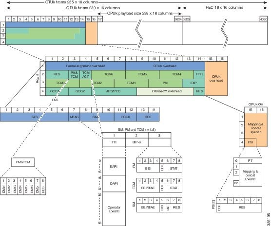
The Trail Trace Identifier (TTI) is a 64-Byte signal that occupies one byte of the frame and is aligned with the OTUk multiframe. It is transmitted four times per multiframe. TTI is defined as a 64-byte string with the following structure:
- TTI [0] contains the Source Access Point Identifier (SAPI) [0] character, which is fixed to all-0s.
-
TTI [1] to TTI [15] contain the 15-character source access point identifier (SAPI[1] to SAPI[15]).
-
TTI [16] contains the Destination Access Point Identifier (DAPI) [0] character, which is fixed to all-0s.
-
TTI [17] to TTI [31] contain the 15-character destination access point identifier (DAPI [1] to DAPI [15]).
-
TTI [32] to TTI [63] are operator specific.
TTI Mismatch
TTI mismatch occurs when you have enabled path trace and the "received string" is different from the "expected string". This alarm condition stops traffic.
When TTI mismatch occurs, the interface is brought to down state. This is only supported for SAPI and DAPI and is not supported for User Operator Data field.
Configuring TTI
To configure TTI:
enable
configure terminal
controller dwdm 0/1/1
shutdown
g709 tti-processing enable
no shutdown
end
Trace Identifier Mismatch (TIM) is reported in the Detected Alarms where there is a mismatch in the expected and received string. Action on detection of TIM can be configured in ODU and OTU layers as follows:
enable
configure terminal
controller dwdm 0/1/1
shutdown
g709 tti-processing enable otu
no shutdown
end
- Configuring TTI for SAPI DAPI Operator Specific Fields
- Verification of TTI SAPI DAPI Operator Specific Fields Configuration
Configuring TTI for SAPI DAPI Operator Specific Fields
To configure TTI SAPI, DAPI, and operator specific fields for OTU and ODU layers:
enable
configure terminal
controller dwdm 0/1/1
g709 fec standard
g709 otu overhead tti sent ascii sapi AABBCCDD
end
Verification of TTI SAPI DAPI Operator Specific Fields Configuration
Use the show controller command to verify TTI SAPI, DAPI, Operator Specific fields configuration:
Router#show controllers dwdm 0/1/1
G709 Information:
Controller dwdm 0/1/1, is up (no shutdown)

Transport mode OTN (10GBASE-R over OPU1e w/o fixed stuffing, 11.0491Gb/s)

<<truncated other output >>

OTU TTI Sent String SAPI ASCII : AABBCCDD
OTU TTI Sent String DAPI ASCII : AABBCCDD
OTU TTI Sent String OPERATOR ASCII : AABBCCDD
OTU TTI Expected String SAPI ASCII : AABBCCDD
OTU TTI Expected String DAPI ASCII : AABBCCDD
OTU TTI Expected String OPERATOR HEX : AABBCCDD
OTU TTI Received String HEX : 0052414D4553480000000000000000000052414D455348000
0000000000000004141424243434444000000000000000000
000000000000000000000000000000

ODU TTI Sent String SAPI ASCII : AABBCCDD
ODU TTI Sent String DAPI ASCII : AABBCCDD
ODU TTI Sent String OPERATOR HEX : 11223344
ODU TTI Expected String SAPI ASCII : AABBCCDD
SNMP Support
Simple Network Management Protocol (SNMP) is an application-layer protocol that provides a message format for communication between SNMP managers and agents. SNMP provides a standardized framework and a common language that is used for monitoring and managing devices in a network.
SNMP sets are not supported for the following tables:
Refer to CISCO-OTN-IF-MIB and SNMP Configuration Guide for SNMP support.
Performance Monitoring
Performance monitoring (PM) parameters are used by service providers to gather, store, set thresholds for, and report performance data for early detection of problems. Thresholds are used to set error levels for each PM parameter. During the accumulation cycle, if the current value of a performance monitoring parameter reaches or exceeds its corresponding threshold value, a threshold crossing alert (TCA) is generated. The TCAs provide early detection of performance degradation. PM statistics are accumulated on a 15-minute basis, synchronized to the start of each quarter-hour. Historical counts are maintained for 33 15-minutes intervals and 2 daily intervals. PM parameters are collected for OTN and FEC.
Calculation and accumulation of the performance-monitoring data is in 15-minute and 24-hour intervals.
PM occurs in near end and far end for both encapsulations for ODUk and OTUk. ODU is referred as Path Monitoring (PM) and OTU is referred to as Section Monitoring (SM).
The following table shows the details of each type of PM parameter for OTN:
|
Parameter |
Definition |
|---|---|
|
BBE-PM |
Path Monitoring Background Block Errors (BBE-PM) indicates the number of background block errors recorded in the optical transport network (OTN) path during the PM time interval. |
|
BBE-SM |
Section Monitoring Background Block Errors (BBE-SM) indicates the number of background block errors recorded in the OTN section during the PM time interval. |
|
BBER-PM |
Path Monitoring Background Block Errors Ratio (BBER-PM) indicates the background block errors ratio recorded in the OTN path during the PM time interval. |
|
BBER-SM |
Section Monitoring Background Block Errors Ratio (BBER-SM) indicates the background block errors ratio recorded in the OTN section during the PM time interval. |
|
ES-PM |
Path Monitoring Errored Seconds (ES-PM) indicates the errored seconds recorded in the OTN path during the PM time interval. |
|
ESR-PM |
Path Monitoring Errored Seconds Ratio (ESR-PM) indicates the errored seconds ratio recorded in the OTN path during the PM time interval. |
|
ESR-SM |
Section Monitoring Errored Seconds Ratio (ESR-SM) indicates the errored seconds ratio recorded in the OTN section during the PM time interval. |
|
ES-SM |
Section Monitoring Errored Seconds (ES-SM) indicates the errored seconds recorded in the OTN section during the PM time interval. |
|
FC-PM |
Path Monitoring Failure Counts (FC-PM) indicates the failure counts recorded in the OTN path during the PM time interval. |
|
FC-SM |
Section Monitoring Failure Counts (FC-SM) indicates the failure counts recorded in the OTN section during the PM time interval. |
|
SES-PM |
Path Monitoring Severely Errored Seconds (SES-PM) indicates the severely errored seconds recorded in the OTN path during the PM time interval. |
|
SES-SM |
Section Monitoring Severely Errored Seconds (SES-SM) indicates the severely errored seconds recorded in the OTN section during the PM time interval. |
|
SESR-PM |
Path Monitoring Severely Errored Seconds Ratio (SESR-PM) indicates the severely errored seconds ratio recorded in the OTN path during the PM time interval. |
|
SESR-SM |
Section Monitoring Severely Errored Seconds Ratio (SESR-SM) indicates the severely errored seconds ratio recorded in the OTN section during the PM time interval. |
|
UAS-PM |
Path Monitoring Unavailable Seconds (UAS-PM) indicates the unavailable seconds recorded in the OTN path during the PM time interval. |
|
UAS-SM |
Section Monitoring Unavailable Seconds (UAS-SM) indicates the unavailable seconds recorded in the OTN section during the PM time interval. |
The following table shows the details of each type of PM parameter for FEC:
|
Parameter |
Definition |
|---|---|
|
EC |
Bit Errors Corrected (BIEC) indicated the number of bit errors corrected in the DWDM trunk line during the PM time interval. |
|
UC-WORDS |
Uncorrectable Words (UC-WORDS) is the number of uncorrectable words detected in the DWDM trunk line during the PM time interval. |
- OTUk Section Monitoring
- ODUk Path Monitoring
- Configuring PM Parameters for FEC
- Configuring PM Parameters for OTN
- Verifying PM Parameters Configuration
OTUk Section Monitoring
Section Monitoring (SM) overhead for OTUk is terminated as follows:
BIP and BEI counters are block error counters (block size equal to OTUk frame size). The counters can be read periodically by a PM thread to derive one second performance counts. They are sufficiently wide for software to identify a wrap-around with up to 1.5 sec between successive readings.
The following OTUk level defects are detected:
Status of the defects is available through CPU readable registers, and a change of status of dLOF, dLOM, and dAIS will generate an interruption.
ODUk Path Monitoring
Path Monitoring (PM) overhead for higher order ODUk and lower order ODUk is processed as follows:
The following ODUk defects are detected:
LOS, OTU LOF, OOF and ODU-AIS alarms bring down the interface in system.
Configuring PM Parameters for FEC
To set TCA report status on FEC layer in 15-minute interval:
enable
configure terminal
controller dwdm 0/1/0
pm 15-min fec report ec-bits enable
pm 15-min fec report uc-words enable
end
To set TCA report status on FEC layer in 24-hour interval:
enable
configure terminal
controller dwdm 0/1/0
pm 24-hr fec report ec-bits enable
pm 24-hr fec report uc-words enable
end
To set threshold on FEC layer in 15-minute interval:
enable
configure terminal
controller dwdm 0/1/0
pm 15-min fec threshold ec-bits
pm 15-min fec threshold uc-words
end
To set threshold on FEC layer in 24-hour interval:
enable
configure terminal
controller dwdm 0/1/0
pm 24-hr fec threshold ec-bits
pm 24-hr fec threshold uc-words
end
Configuring PM Parameters for OTN
To set OTN report status in 15-minute interval:
enable
configure terminal
controller dwdm 0/1/0
pm 15-min otn report es-pm-ne enable
end
To set OTN report status in 24-hour interval:
enable
configure terminal
controller dwdm slot/bay/port
pm 24-hr otn report es-pm-ne enable
end
To set OTN threshold in 15-minute interval:
enable
configure terminal
controller dwdm 0/1/0
pm 15-min otn threshold es-pm-ne
end
To set OTN threshold in 24-hour interval:
enable
configure terminal
controller dwdm 0/1/0
pm 24-hr otn threshold es-pm-ne
end
Verifying PM Parameters Configuration
Use the show controllers command to verify PM parameters configuration for FEC in 15-minute interval:
Router#show controllers dwdm 0/1/0 pm interval 15-min fec 0
g709 FEC in the current interval [9 :15:00 - 09:16:40 Thu Jun 9 2016]

FEC current bucket type : INVALID
    EC-BITS   :            0    Threshold :          200   TCA(enable)  : YES
    UC-WORDS  :            0    Threshold :           23  TCA(enable)  : YES


Router#show controllers dwdm 0/1/0 pm interval 15-min fec 1
g709 FEC in interval 1 [9 :00:00 - 9 :15:00 Thu Jun 9 2016]

FEC current bucket type : VALID
    EC-BITS   :            0      UC-WORDS  :            0
Use the show controllers command to verify PM parameters configuration for FEC in 24-hour interval:
Router#show controllers dwdm 0/1/0 pm interval 24 fec 0
g709 FEC in the current interval [00:00:00 - 09:17:01 Thu Jun 9 2016]

FEC current bucket type : INVALID
    EC-BITS   :            0    Threshold :            0   TCA(enable)  : NO
    UC-WORDS  :            0    Threshold :            0  TCA(enable)  : NO


Router#show controllers dwdm 0/1/0 pm interval 24 fec 1
g709 FEC in interval 1 [00:00:00 - 24:00:00 Wed Jun 8 2016]

FEC current bucket type : VALID
    EC-BITS   :          717      UC-WORDS  :      1188574
Use the show controllers command to verify PM parameters configuration for OTN in 15-minute interval:
Router#show controllers dwdm 0/1/0 pm interval 15-min otn 0
g709 OTN in the current interval [9 :15:00 - 09:15:51 Thu Jun 9 2016]

OTN current bucket type: INVALID

OTN Near-End Valid : YES
    ES-SM-NE    :        0     Threshold :        0   TCA(enable)  : NO
    ESR-SM-NE   :  0.00000     Threshold :  0.00010   TCA(enable)  : YES
    SES-SM-NE   :        0     Threshold :        0   TCA(enable)  : NO
    SESR-SM-NE  :  0.00000     Threshold :  0.02300   TCA(enable)  : NO
    UAS-SM-NE   :        0     Threshold :        0   TCA(enable)  : NO
    BBE-SM-NE   :        0     Threshold :        0   TCA(enable)  : NO
    BBER-SM-NE  :  0.00000     Threshold :  0.02300   TCA(enable)  : NO
    FC-SM-NE    :        0     Threshold :        0   TCA(enable)  : NO
    ES-PM-NE    :        0     Threshold :      200   TCA(enable)  : YES
    ESR-PM-NE   :  0.00000     Threshold :  1.00000   TCA(enable)  : NO
    SES-PM-NE   :        0     Threshold :        0   TCA(enable)  : NO
    SESR-PM-NE  :  0.00000     Threshold :  0.02300   TCA(enable)  : NO
    UAS-PM-NE   :        0     Threshold :        0   TCA(enable)  : NO
    BBE-PM-NE   :        0     Threshold :        0   TCA(enable)  : NO
    BBER-PM-NE  :  0.00000     Threshold :  0.02300   TCA(enable)  : NO
    FC-PM-NE    :        0     Threshold :        0   TCA(enable)  : NO


OTN Far-End Valid : YES
    ES-SM-FE    :        0       Threshold :        0   TCA(enable)  : NO
    ESR-SM-FE   :  0.00000       Threshold :  1.00000   TCA(enable)  : NO
    SES-SM-FE   :        0       Threshold :        0   TCA(enable)  : NO
    SESR-SM-FE  :  0.00000       Threshold :  0.02300   TCA(enable)  : NO
    UAS-SM-FE   :        0       Threshold :        0   TCA(enable)  : NO
    BBE-SM-FE   :        0       Threshold :        0   TCA(enable)  : NO
    BBER-SM-FE  :  0.00000       Threshold :  0.02300   TCA(enable)  : NO
    FC-SM-FE    :        0       Threshold :        0   TCA(enable)  : NO
    ES-PM-FE    :        0       Threshold :        0   TCA(enable)  : NO
    ESR-PM-FE   :  0.00000       Threshold :  1.00000   TCA(enable)  : NO
    SES-PM-FE   :        0       Threshold :        0   TCA(enable)  : NO
    SESR-PM-FE  :  0.00000       Threshold :  0.02300   TCA(enable)  : NO
    UAS-PM-FE   :        0       Threshold :        0   TCA(enable)  : NO
    BBE-PM-FE   :        0       Threshold :        0   TCA(enable)  : NO
    BBER-PM-FE  :  0.00000       Threshold :  0.02300   TCA(enable)  : NO
    FC-PM-FE    :        0       Threshold :        0   TCA(enable)  : NO


Router#show controllers dwdm 0/1/0 pm interval 15-min otn 1
g709 OTN in interval 1 [9 :00:00 - 9 :15:00 Thu Jun 9 2016]

OTN current bucket type: VALID

OTN Near-End Valid : YES        OTN Far-End Valid : YES
    ES-SM-NE    :        0         ES-SM-FE    :        0
    ESR-SM-NE   :  0.00000         ESR-SM-FE   :  0.00000
    SES-SM-NE   :        0         SES-SM-FE   :        0
    SESR-SM-NE  :  0.00000         SESR-SM-FE  :  0.00000
    UAS-SM-NE   :        0         UAS-SM-FE   :        0
    BBE-SM-NE   :        0         BBE-SM-FE   :        0
    BBER-SM-NE  :  0.00000         BBER-SM-FE  :  0.00000
    FC-SM-NE    :        0         FC-SM-FE    :        0
    ES-PM-NE    :        0         ES-PM-FE    :        0
    ESR-PM-NE   :  0.00000         ESR-PM-FE   :  0.00000
    SES-PM-NE   :        0         SES-PM-FE   :        0
    SESR-PM-NE  :  0.00000         SESR-PM-FE  :  0.00000
    UAS-PM-NE   :        0         UAS-PM-FE   :        0
    BBE-PM-NE   :        0         BBE-PM-FE   :        0
    BBER-PM-NE  :  0.00000         BBER-PM-FE  :  0.00000
    FC-PM-NE    :        0         FC-PM-FE    :        0
Router#show controllers dwdm 0/1/0 pm interval 24-hour otn 0
g709 OTN in the current interval [00:00:00 - 09:16:10 Thu Jun 9 2016]

OTN current bucket type: INVALID

OTN Near-End Valid : YES
    ES-SM-NE    :        0     Threshold :        0   TCA(enable)  : NO
    ESR-SM-NE   :  0.00000     Threshold :  0.00000   TCA(enable)  : NO
    SES-SM-NE   :        0     Threshold :        0   TCA(enable)  : NO
    SESR-SM-NE  :  0.00000     Threshold :  0.00000   TCA(enable)  : NO
    UAS-SM-NE   :        0     Threshold :        0   TCA(enable)  : NO
    BBE-SM-NE   :        0     Threshold :        0   TCA(enable)  : NO
    BBER-SM-NE  :  0.00000     Threshold :  0.00000   TCA(enable)  : NO
    FC-SM-NE    :        0     Threshold :        0   TCA(enable)  : NO
    ES-PM-NE    :        0     Threshold :        0   TCA(enable)  : NO
    ESR-PM-NE   :  0.00000     Threshold :  0.00000   TCA(enable)  : NO
    SES-PM-NE   :        0     Threshold :        0   TCA(enable)  : NO
    SESR-PM-NE  :  0.00000     Threshold :  0.00000   TCA(enable)  : NO
    UAS-PM-NE   :        0     Threshold :        0   TCA(enable)  : NO
    BBE-PM-NE   :        0     Threshold :        0   TCA(enable)  : NO
    BBER-PM-NE  :  0.00000     Threshold :  0.00000   TCA(enable)  : NO
    FC-PM-NE    :        0     Threshold :        0   TCA(enable)  : NO


OTN Far-End Valid : YES
    ES-SM-FE    :        0       Threshold :        0   TCA(enable)  : NO
    ESR-SM-FE   :  0.00000       Threshold :  0.00000   TCA(enable)  : NO
    SES-SM-FE   :        0       Threshold :        0   TCA(enable)  : NO
    SESR-SM-FE  :  0.00000       Threshold :  0.00000   TCA(enable)  : NO
    UAS-SM-FE   :        0       Threshold :        0   TCA(enable)  : NO
    BBE-SM-FE   :        0       Threshold :        0   TCA(enable)  : NO
    BBER-SM-FE  :  0.00000       Threshold :  0.00000   TCA(enable)  : NO
    FC-SM-FE    :        0       Threshold :        0   TCA(enable)  : NO
    ES-PM-FE    :        0       Threshold :        0   TCA(enable)  : NO
    ESR-PM-FE   :  0.00000       Threshold :  0.00000   TCA(enable)  : NO
    SES-PM-FE   :        0       Threshold :        0   TCA(enable)  : NO
    SESR-PM-FE  :  0.00000       Threshold :  0.00000   TCA(enable)  : NO
    UAS-PM-FE   :        0       Threshold :        0   TCA(enable)  : NO
    BBE-PM-FE   :        0       Threshold :        0   TCA(enable)  : NO
    BBER-PM-FE  :  0.00000       Threshold :  0.00000   TCA(enable)  : NO
    FC-PM-FE    :        0       Threshold :        0   TCA(enable)  : NO


Router#show controllers dwdm 0/1/0 pm interval 24-hour otn 1
g709 OTN in interval 1 [00:00:00 - 24:00:00 Wed Jun 8 2016]

OTN current bucket type: INVALID

OTN Near-End Valid : YES        OTN Far-End Valid : NO
    ES-SM-NE    :        7         ES-SM-FE    :        0
    ESR-SM-NE   :  0.00000         ESR-SM-FE   :  0.00000
    SES-SM-NE   :        7         SES-SM-FE   :        0
    SESR-SM-NE  :  0.00000         SESR-SM-FE  :  0.00000
    UAS-SM-NE   :       41         UAS-SM-FE   :        0
    BBE-SM-NE   :        0         BBE-SM-FE   :        0
    BBER-SM-NE  :  0.00000         BBER-SM-FE  :  0.00000
    FC-SM-NE    :        3         FC-SM-FE    :        0
    ES-PM-NE    :        2         ES-PM-FE    :        1
    ESR-PM-NE   :  0.00000         ESR-PM-FE   :  0.00000
    SES-PM-NE   :        0         SES-PM-FE   :        0
    SESR-PM-NE  :  0.00000         SESR-PM-FE  :  0.00000
    UAS-PM-NE   :        0         UAS-PM-FE   :        0
    BBE-PM-NE   :        3         BBE-PM-FE   :        1
    BBER-PM-NE  :  0.00000         BBER-PM-FE  :  0.00000
    FC-PM-NE    :        0         FC-PM-FE    :        0
If TCA is enabled for OTN or FEC alarm, a syslog message is displayed for the 15-minute or 24-hour interval as follows:
*Jun 9 09:18:02.274: %PMDWDM-4-TCA: dwdm-0/1/0: G709 ESR-SM NE value (540) threshold (10) 15-min
Troubleshooting Scenarios
The following table shows the troubleshooting solutions for the feature.
|
Problem |
Solution |
|---|---|
|
Link is not coming up |
Perform shut and no shut actions of the interface. Check for TTI Mismatch. Verify the major alarms. Verify the FEC mode. Verify that Cisco supported transreceiver list is only used on both sides . |
| Incrementing BIP Error |
Verify FEC Mismatch. |
| FEC contains UC and EC errors and link is not coming up |
Verify the FEC Mismatch. |
Associated Commands
The following commands are used to configure OTN Wrapper:
|
Commands |
Links |
|---|---|
|
controller dwdm |
|
|
g709 disable |
|
|
g709 fec |
|
|
g709 odu report |
|
|
g709 odu threshold |
|
|
g709 otu report |
|
|
g709 otu threshold |
|
|
g709 overhead |
|
|
g709 tti processing |
|
|
pm fec threshold |
|
|
pm otn report |
|
|
pm otn threshold |
|
|
show controller dwdm |
|
|
show interfaces |
|
|
transport-mode |
 Feedback