Cisco ASR 9000 Series Aggregation Services Router MPLS Configuration Guide, Release 5.3.x
Bias-Free Language
The documentation set for this product strives to use bias-free language. For the purposes of this documentation set, bias-free is defined as language that does not imply discrimination based on age, disability, gender, racial identity, ethnic identity, sexual orientation, socioeconomic status, and intersectionality. Exceptions may be present in the documentation due to language that is hardcoded in the user interfaces of the product software, language used based on RFP documentation, or language that is used by a referenced third-party product. Learn more about how Cisco is using Inclusive Language.
This module describes how to implement MPLS transport profile (MPLS-TP) on the router. MPLS-TP supported by IETF enables the
migration of transport networks to a packet-based network that efficiently scale to support packet services in a simple and
cost-effective way. MPLS-TP combines the necessary existing capabilities of MPLS with additional minimal mechanisms in order
that it can be used in a transport role.
MPLS transport profile enables you to create tunnels that provide the transport network service layer over which IP and MPLS
traffic traverse.
Feature History for Implementing MPLS Transport Profile
Release
Modification
Release
4.2.0
This feature was introduced.
Restrictions for MPLS-TP
Penultimate hop popping is not supported. Only ultimate hop popping is supported, because label mappings are configured at
the MPLS-TP endpoints.
MPLS-TP links must be configured with IP addresses.
IPv6 addressing is not supported.
L2VPN Restrictions
Pseudowire ID Forward Equivalence Class (FEC) (type 128) is supported, but generalized ID FEC (type 129) is not supported.
BFD over pseudowire is not supported. Static pseudowire OAM protocol is used to signal fault on static pseudowire placed over
TP tunnels using pseudowire status.
Only Ethernet pseudowire type is supported.
Information About Implementing MPLS Transport Profile
To implement MPLS-TP, you should understand these concepts:
MPLS Transport Profile
MPLS Transport Profile (TP) enables you to create tunnels that provide the transport network service layer over which IP and
MPLS traffic traverse. MPLS-TP tunnels enable a transition from Synchronous Optical Networking (SONET) and Synchronous Digital
Hierarchy (SDH) time-division multiplexing (TDM) technologies to packet switching, to support services with high bandwidth
utilization and low cost. Transport networks are connection oriented, statically provisioned, and have long-lived connections.
Transport networks usually avoid control protocols that change identifiers like labels. MPLS-TP tunnels provide this functionality
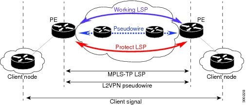
through statically provisioned bidirectional label switched paths (LSPs). This figure shows the MPLS-TP tunnel:
Figure 1. MPLS Transport Profile Tunnel
MPLS-TP combines the necessary existing capabilities of MPLS with additional minimal mechanisms in order that it can be used
in a transport role. You can set up MPLS-TP through a CLI or a network management system.
MPLS-TP tunnels have these characteristics:
An MPLS-TP tunnel can be associated with working LSP, protect LSP, or both LSP
1:1 path protection with revertive mode for MPLS-TP LSP with
revertive mode for MPLS-TP LSP
Use of Generic Alert Label (GAL) and Generic Associated Channel Header (G-ACH) to transport control packets; for example,
BFD packets and pseudowire OAM packets
BFD is used as a continuity check (CC) mechanism over MPLS-TP LSP
Remote Defect Indication (RDI) based on BFD
Fault OAM functions
These services are supported over MPLS-TP tunnels:
Dynamic spoke pseudowire (for H-VPLS) over static MPLS-TP tunnels.
Static spoke pseudowire (for H-VPLS) over static MPLS-TP tunnels.
MS-PW services where static and dynamic pseudowire segments can be concatenated.
MPLS ping and traceroute over MPLS TP LSP and PW.
Static routes over MPLS-TP tunnels.
Pseudowire redundancy for static pseudowire.
VPWS using static or dynamic pseudowire pinned down to MPLS-TP tunnels.
VPLS and H-VPLS using static or dynamic pseudowire pinned down to MPLS-TP tunnels.
Bidirectional LSPs
MPLS transport profile (MPLS-TP) LSPs are bidirectional and congruent where LSPs traverse the same path in both directions.
An MPLS-TP tunnel can be associated with either working MPLS-TP LSP, protect MPLS-TP LSP, or both. The working LSP is the
primary LSP backed up by the protect LSP. When a working LSP goes down, protect LSP is automatically activated. In order for
an MPLS-TP tunnel to be operationally up, it must be configured with at least one LSP.
MPLS-TP Path Protection
Path protection provides an end-to-end failure recovery mechanism (that is, full path protection) for MPLS-TP tunnels. MPLS-TP
LSPs support 1:1 path protection. You can configure the working and protect LSPs as part of configuring the MPLS-TP tunnel.
The working LSP is the primary LSP used to route traffic, while the protect LSP is a backup for a working LSP. If the working
LSP fails, traffic is switched to the protect LSP until the working LSP is restored, at which time traffic forwarding reverts
back to the working LSP (revertive mode).
Fault OAM Support
The fault OAM protocols and messages support the provisioning and
maintenance of MPLS-TP tunnels and bidirectional LSPs:
Generic Associated Channel
Generic Associated Channel (G-ACh)
is the control channel mechanism associated with MPLS LSPs in
addition to MPLS pseudowire. The G-ACh Label (GAL) (Label 13) is a
generic alert label to identify the presence of the G-ACh in the
label packet. It is taken from the reserved MPLS label space.
G-ACh or GAL is used to support in-band OAMs of MPLS-TP LSPs and pseudowires.
The OAM messages are used for fault management, connection
verification, continuity check and other functions.
These messages are forwarded along the specified
MPLS LSP:
OAM Fault Management: Alarm Indication Signal (AIS), Link Down Indication
(LDI), and Lock Report (LKR)
messages (GAL with fault-OAM channel)
OAM Connection Verification: Ping and traceroute messages (GAL with IP channel)
BFD messages (GAL with BFD channel)
These messages are forwarded along the specified pseudowire:
Fault Management: Alarm Indication Signal (AIS), Link Down Indication
(LDI), and Lock Report (LKR)
messages
LDI messages are generated at midpoint nodes when a
failure is detected. The midpoint sends the LDI message
to the endpoint that is reachable with the existing failure.
The midpoint node also sends LKR messages to the reachable endpoint, when an interface is administratively down. AIS
messages are not generated by Cisco platforms, but are processed if received.
By default, the reception of LDI and LKR on the active LSP at an
endpoint will cause a path protection switchover, while AIS will
not.
Fault Management: Emulated Protection
Switching for LSP Lockout
You can implement a form of Emulated
Protection Switching in support of LSP Lockout using customized
fault messages. When a Cisco Lockout message is sent, it does not
cause the LSP to be administratively down. The Cisco Lockout
message causes a path protection switchover and prevents data
traffic from using the LSP. The LSP's data path remains up so that BFD and
other OAM messages can continue to traverse it. Maintenance of the
LSP can take place such as reconfiguring or replacing a midpoint
LSR. BFD state over LSP must be up and MPLS ping and traceroute can be used to verify the LSP connectivity, before
the LSP is put back into service by removing the lockout. You cannot lockout working and protect LSPs simultaneously.
LSP ping and traceroute
For MPLS-TP connectivity
verification, you can use ping mpls traffic-eng tunnel-tp
and traceroute mpls traffic-eng tunnel-tp commands. You can
specify that the echo requests be sent along the working
LSP or the protect LSP. You can also specify that
the echo request be sent on a locked out MPLS-TP tunnel LSP (either
working or protect) if the working or protect LSP is explicitly
specified.
Continuity Check through BFD
BFD session is automatically created on MPLS-TP LSPs with default parameters. You can override the default BFD parameters
either through global commands or per-tunnel commands. Furthermore, you can optionally specify different BFD parameters for
standby LSPs. For example, when an LSP is in standby, BFD hello messages can be sent at smaller frequency to reduce line-card
CPU usage. However, when a standby LSP becomes active (for example, due to protection switching), nominal BFD parameters are
used for that LSPs (for example, to run BFD hello messages at higher frequency). For more information about BFD, see the Configuring Bidirectional Forwarding Detection on the Cisco ASR
9000 Series Router
in the Cisco ASR 9000 Series Aggregation Services Router Interface and Hardware Component Configuration Guide.
MPLS-TP Links and Physical Interfaces
MPLS-TP link IDs may be assigned to physical interfaces only.
Bundled interfaces and virtual interfaces are not supported for
MPLS-TP link IDs.
The MPLS-TP link is used to create a level of indirection
between the MPLS-TP tunnel and midpoint LSP configuration and the
physical interface. The MPLS-TP link-id
command is used to associate an MPLS-TP link ID with a physical
interface and next-hop node address.
Multiple tunnels and LSPs may then refer to the MPLS-TP link to
indicate they are traversing that interface. You can move the
MPLS-TP link from one interface to another without reconfiguring
all the MPLS-TP tunnels and LSPs that refer to the link.
Link IDs must be unique on the router or node. For more information, see the Configuring MPLS-TP Links and Physical Interfaces section.
Tunnel LSPs
Tunnel LSPs, whether endpoint or midpoint, use the same identifying information. However, it is entered differently.
A midpoint consists of a forward LSP and a reverse LSP. A MPLS-TP LSP mid point is identified by its name, and forward LSP,
reverse LSP, or both are configured under a submode.
At the midpoint, determining which end is source and
which is destination is arbitrary. That is, if you are configuring
a tunnel between your router and a coworker's router, then your
router is the source. However, your coworker considers his or her
router to be the source. At the midpoint, either router could be
considered the source. At the midpoint, the forward direction is
from source to destination, and the reverse direction is from
destination to source. For more information, see the Configuring MPLS-TP LSPs at Midpoints section.
At the midpoint, the LSP number does not assume default values, and hence must be explicitly configured.
At the endpoint, the local information (source) either comes from the global node ID and global ID, or from locally configured
information using the source command after you enter the interface tunnel-tp number command, where number is the local or source tunnel-number.
At the endpoint, the remote information (destination) is configured using the destination command after you enter the interface tunnel-tp number command. The destination command includes the destination node ID, optionally the global ID, and optionally the destination tunnel number. If you
do not specify the destination tunnel number, the source tunnel number is used.
MPLS-TP IP-less support
Generally, MPLS-TP functionality can be deployed with or without an IP address. However, the main motivation for the IP-less
model is this: an LSR can be inserted into an MPLS-TP network without changing the configurations on adjacent LSRs. In the
past Cisco IOS-XR MPLS-TP release, if an interface does not have a valid IP address, BFD packets cannot be transmitted over
that link, and hence MPLS-TP LSP cannot be brought up on that link. In this release, the IP-less TP link operates only in
a point-to-point mode.
This feature, therefore, makes the need for an IP address on a TP link optional. You may deploy LSRs running Cisco IOS-XR
in MPLS-TP networks with or without an IP address. With such extra flexibility, LSRs running Cisco IOS-XR can be easily deployed
not only with LSRs running IOS, but with LSRs from other vendors too.
MPLS-TP LSP Wrapping
In the MPLS-TP LSP Wrapping protection scheme, a protected MPLS-TP tunnel is associated
with a working LSP and protect LSP. This helps to prevent traffic
loss as soon as a mid-point LSR detects a failure at physical layer
rather than waiting for BFD to time-out. Also, a delay in activating protection switch due to mid-point failure does not further
increase the traffic
loss.
MPLS-TP LSP wrapping has to enabled only on the MID node. MPLS-TP LSP wrapping helps in detecting mid-link failure scenarios;
other
failures and failures on end node is detected by BFD timeout and
TP-OAM message.
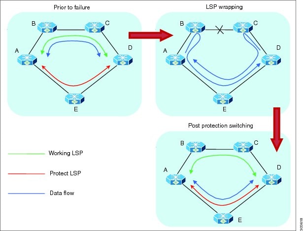
As shown in the figure below, when an LSR (e.g., Router B) detects a failure, it forwards the incoming traffic over an impacted
LSP onto the reverse LSP, if it exists. The traffic re-directed into the reverse LSP is loopback traffic. Looping back traffic
is carried out by the forwarding engine without control plane's involvement. The label stack of a loopback packet will be
modified such that the source of the traffic identifies the packet.
Figure 2. MPLS-TP LSP Wrapping Mechanism
When the forwarding engine at an end-point recognizes a packet
from loopback traffic, it
sforwards the packet on protect LSP. As BFD
packets over impacted LSPs are also looped-back, the end-point will
drop such BFD packets so that BFD sessions over the impacted LSPs
is timed-out and protection switching is activated.
Optionally, when an end-point receives the first looped-back
packet, it activates protection switching.
A working LSP remains wrapped until protection switching is
activated. Once activated, protect LSP will carry traffic as
usual. When failure is removed and BFD session comes back up
resulting in activation of working LSP.
How to Implement MPLS Transport Profile
MPLS Transport Profile (MPLS-TP) supported by IETF enables the migration of transport networks to a packet-based network
that efficiently scale to support packet services in a simple and cost effective way.
These procedures are used to implement MPLS-TP:
Configuring the Node ID and Global ID
Perform this task to configure node ID and global ID on the router.
SUMMARY STEPS
configure
mpls traffic-eng
tp
node-id node-id
global-id num
commit
DETAILED STEPS
Command or Action
Purpose
Step 1
configure
Step 2
mpls traffic-eng
Example:
RP/0/RSP0/CPU0:router(config)# mpls traffic-eng
Enters MPLS TE configuration mode.
Step 3
tp
Example:
RP/0/RSP0/CPU0:router(config-mpls-te)# mpls tp
Enters MPLS transport profile (TP) configuration mode. You can configure MPLS TP specific parameters for the router from
this mode.
Specifies the default global ID used for all endpoints and midpoints. This command makes the node ID globally unique in a
multi-provider tunnel. Otherwise, the node ID is only locally meaningful.
Note
The global ID is a 32-bit number, and can be assigned to each node.
Step 6
commit
Configuring Pseudowire OAM Attributes
Perform this task to configure pseudowire OAM attributes.
Exits from working LSP interface configuration mode.
Step 12
protect-lsp
Example:
RP/0/RSP0/CPU0:router(config-if)# protect-lsp
Specifies a backup for a working LSP. If the working LSP fails, traffic is switched to the protect LSP until the working
LSP is restored, at which time traffic forwarding reverts back to the working LSP.
Configures an interface type and path ID to be associated with a MPLS TE mode.
Note
You must provide the next-hop IP address.
Note
You can define a link ID once. If you attempt to use the same MPLS-TP link ID with different interface or next-hop address,
the configuration gets rejected. You have to remove the existing link ID configuration before using the same link ID with
a different interface or next-hop address.
Step 5
commit
Configuring MPLS-TP LSP Wrapping
Perform this task to configure the MPLS-TP LSP wrapping.
Note
When configuring the LSPs at the midpoint routers, make sure that the configuration does not reflect traffic back to the
originating node.

 Feedback