Overview of the Cisco SM-X-16G4M2X or SM-X-40G8M2X EtherSwitch Service Module
Cisco SM-X-16G4M2X or SM-X-40G8M2X is a layer-2 switch module that brings high-density Small Form-Factor Pluggable (SFP) /Small Form-Factor Pluggable Plus (SFP+), 1 Gigabit, 2.5 mGiG, and 10G connectivity to the Cisco 4000 Series Integrated Services Routers (ISRs). It also, provides 10G-capable internal uplink to central forwarding data plane on modular ISR platforms.
The SM-X-16G4M2X or SM-X-40G8M2X service module is capable of supporting standard Power over Ethernet (PoE), Power over Ethernet Plus (PoE+), Cisco Enhanced Power over Ethernet (EPoE), and Cisco Universal Power over Ethernet (UPoE) on all copper ports. A maximum of 60 watts of power for each copper port is supported by leveraging both signal and spare pairs.
This guide describes how to configure the SM-X-16G4M2X or SM-X-40G8M2X service module in the Cisco 4000 Series Integrated Services Router (ISR).
The following is the feature history for the SM-X-16G4M2X or SM-X-40G8M2X service module:
|
Release |
Modification |
|---|---|
|
Cisco IOS XE Gibraltar 16.12.1a |
Cisco SM-X-16G4M2X Service Module was introduced. |
|
Cisco IOS XE Gibraltar 16.12.1a |
Cisco SM-X-40G8M2X Service Module was introduced. |
Finding Support Information for Platforms and Cisco IOS Software Images
Your software release may not support all the features documented in this module. For the latest feature information and caveats, see the release notes for your platform and software release. Use Cisco Feature Navigator to find information about platform support and Cisco software image support. To access Cisco Feature Navigator, go to http://www.cisco.com/go/cfn . An account on Cisco.com is not required.
Configuring the Cisco SM-X-16G4M2X or SM-X-40G9M2X Service Module
This section describes how to configure the Cisco SM-X-16G4M2X or SM-X-40G9M2X service module features and some important concepts about the Cisco SM-X-16G4M2X or SM-X-40G9M2X service module.
Prerequisites for the Cisco SM-X-16G4M2X Service Module
Cisc IOS XE Gibraltar 16.12.1a release is required to configure the Cisco SM-X-16G4M2X.
-
Run the show version command to determine the version of Cisco IOS software running on your router.
-
To view the router (Cisco 4000 Series ISR), Cisco IOS software release, and feature set, enter the show version command in privileged EXEC mode.
-
To view the Cisco IOS Release number mapping, see Release Notes for the Cisco ISR 4400 Series.
Restrictions for Configuring Cisco SM-X-16G4M2X Service Module
This section describes the restrictions for Cisco SM-X-16G4M2X service module:
-
Cisco NIM-ES2-4/NIM-ES2-8 and SM-X-16G4M2X cannot co-existence within a single chassis due to feature incompatibility. When you switch between two modes, you need to reload the system.

Note
When both the Cisco SM-X-16G4M2X and NIM-ES2-4/NIM-ES2-8 modules are inserted in the same router, the Cisco SM-X-16G4M2X service module takes the priority. The router reboots and works in the next-gen switching mode instead of legacy switching mode. After the reload, Cisco NIM-ES2-4/NIM-ES2-8 goes out of service and the Cisco SM-X-16G4M2X service module is active.
Configuring Power Over Ethernet
Before you begin
Each copper port on the SM-X-16G4M2X service modue can auto detect one of following connected devices, and supply power to them properly:
-
An IEEE 802.3af and IEEE 802.3at compliant power device
-
Cisco EPOE and UPOE power device
To configure power over ethernet, use these commads:
SUMMARY STEPS
- configure terminal
- interface interface id
- power inline [auto | max max-wattage] never
- end
DETAILED STEPS
| Command or Action | Purpose | |||
|---|---|---|---|---|
|
Step 1 |
configure terminal Example: |
Enters global configuration mode. |
||
|
Step 2 |
interface interface id Example: |
Specifies the physical port to be configured, and enters interface configuration mode. |
||
|
Step 3 |
power inline [auto | max max-wattage] never Example: |
Configures the PoE mode on the port. The keywords have these meanings:
|
||
|
Step 4 |
end Example: |
Returns to privileged EXEC mode. |
Verifying the Power Over Ethernet
To verify the power over ethernet configuration, user the show power inline command as shown in the following example.
Router#show power inline
Available:500.0(w)  Used:100.3(w)  Remaining:399.8(w)

Interface Admin  Oper       Power   Device              Class Max
                            (Watts)
--------- ------ ---------- ------- ------------------- ----- ----
Gi2/0/0   auto   on         30.0    AIR-AP3802I-H-K9    4     60.0
Gi2/0/1   auto   on         10.3    IP Phone 7970       3     60.0
Gi2/0/2   auto   off        0.0     n/a                 n/a   60.0
Gi2/0/3   auto   off        0.0     n/a                 n/a   60.0
Gi2/0/4   auto   off        0.0     n/a                 n/a   60.0
Gi2/0/5   auto   off        0.0     n/a                 n/a   60.0
Gi2/0/6   auto   off        0.0     n/a                 n/a   60.0
Gi2/0/7   auto   off        0.0     n/a                 n/a   60.0
Gi2/0/8   auto   off        0.0     n/a                 n/a   60.0
Gi2/0/9   auto   off        0.0     n/a                 n/a   60.0
Gi2/0/10  auto   off        0.0     n/a                 n/a   60.0
Gi2/0/11  auto   off        0.0     n/a                 n/a   60.0
Gi2/0/12  auto   off        0.0     n/a                 n/a   60.0
Gi2/0/13  auto   off        0.0     n/a                 n/a   60.0
Gi2/0/14  auto   off        0.0     n/a                 n/a   60.0
Gi2/0/15  auto   off        0.0     n/a                 n/a   60.0
Tw2/0/16  auto   off        0.0     n/a                 n/a   60.0
Tw2/0/17  auto   on         30.0    AIR-AP3802I-H-K9    4     60.0
Tw2/0/18  auto   off        0.0     n/a                 n/a   60.0
Tw2/0/19  auto   on         30.0    AIR-AP3802I-H-K9    4     60.0
Configuring Universal PoE
Cisco UPOE can provide a maximum of 60Watts power over both signal and spare paris of RJ45 cable. UPOE capable switch port can enable spare pair and supply power to it through CDP or LLDP negotiations with UPOE power device automatically.
If end-point power device is capable to consume power on both signal and spare pairs but without corresponding CDP/LLDP negotiation mechanism available, following configurations can be used to manually force four-pair on specific port.
SUMMARY STEPS
- configure terminal
- interface interface id
- power inline four-pair forced
- end
DETAILED STEPS
| Command or Action | Purpose | |
|---|---|---|
|
Step 1 |
configure terminal Example: |
Enters global configuration mode. |
|
Step 2 |
interface interface id Example: |
Specifies the physical port to be configured, and enters interface configuration mode. |
|
Step 3 |
power inline four-pair forced Example: |
Forces power enabling on both signal and spare pairs from a switch port. |
|
Step 4 |
end Example: |
Returns to privileged EXEC mode. |
Configuring Gigabit Ethernet Interfaces
To configure speed and duplex operation, follow these steps in interface configuration mode:
Before you begin
The GigabitEthernet interface can be either manually configured as 10Mbps, 100Mbps or 1Gbps mode, or auto-negotiated to proper working mode with link peer.
SUMMARY STEPS
- duplex [ full|auto ]
- speed [ 10|100|1000|auto ]
DETAILED STEPS
| Command or Action | Purpose | |
|---|---|---|
|
Step 1 |
duplex [ full|auto ] Example: |
|
|
Step 2 |
speed [ 10|100|1000|auto ] Example: |
|
Configuring Two-Gigabit Ethernet Interfaces
To configure mGig, follow these steps in interface configuration mode:
Before you begin
The mGiG ethernet interface can be manually configured as 100Mbps, 1Gbps or 2.5Gbps mode, or auto-negotiated with peer link over the commonly used cat5e cable or higher cable variants.
SUMMARY STEPS
- duplex [ full|auto ]
- speed [ 100|1000|2500|auto ]
DETAILED STEPS
| Command or Action | Purpose | |
|---|---|---|
|
Step 1 |
duplex [ full|auto ] Example: |
|
|
Step 2 |
speed [ 100|1000|2500|auto ] Example: |
|
Configuring Ten-Gigabit Ethernet Interfaces
You cannot configure the duplex and speed on the Ten-Gigabit ethernet interface. Its speed depends on the type of SFP or SFP+ inserted into the port.
Configuring Flowcontrol and Maximum Transmission Unit
Flow control allows congested port to pause traffic at the peer node. If one port experiences congestion on egress direction, it notifies other ports using pause frames to stop transferring packets to it during congestion period.
Note |
Cisco SM-X-16G4M2X switch ports support only receive direction flow control, which are aligned with other Catalyst switches. |
The default maximum transmission unit (MTU) size for frames received and sent on all switch interfaces is 1500 bytes. You can change the MTU size to support jumbo frames on all external interfaces.
SUMMARY STEPS
- flowcontrol receive [on | off]
- mtu mtu size
DETAILED STEPS
| Command or Action | Purpose | |
|---|---|---|
|
Step 1 |
flowcontrol receive [on | off] Example: |
The default state is off.
|
|
Step 2 |
mtu mtu size Example: |
Sets the maximum transmission unit (MTU) size for a frame. The range from 1500 to 9216. |
Verifying the Ethernet Interface Status
To view the status of the Gigabit interface, use the show interfaces GigabitEthernet command.
Router#show interfaces gigabitEthernet 2/0/14
GigabitEthernet2/0/14 is up, line protocol is up (connected)
  Hardware is SM-X-16G4M2X, address is f4db.e673.fa15 (bia f4db.e673.fa15)
  MTU 3000 bytes, BW 1000000 Kbit/sec, DLY 10 usec,
     reliability 255/255, txload 1/255, rxload 1/255
  Encapsulation ARPA, loopback not set
  Keepalive not supported
  Full-duplex, 1000Mb/s, link type is auto, media type is 10/100/1000BaseTX
  input flow-control is on, output flow-control is unsupported
  ARP type: ARPA, ARP Timeout 04:00:00
  Last input never, output 00:00:01, output hang never
  Last clearing of "show interface" counters never
  Input queue: 0/375/0/0 (size/max/drops/flushes); Total output drops: 0
  Queueing strategy: fifo
  Output queue: 0/40 (size/max)
  5 minute input rate 0 bits/sec, 0 packets/sec
  5 minute output rate 0 bits/sec, 0 packets/sec
     258911616529 packets input, 33140686915712 bytes, 0 no buffer
     Received 0 broadcasts (0 multicasts)
     0 runts, 0 giants, 0 throttles
     0 input errors, 0 CRC, 0 frame, 0 overrun, 0 ignored
     0 watchdog, 0 multicast, 0 pause input
     0 input packets with dribble condition detected
     258846666089 packets output, 33132365295921 bytes, 0 underruns
     0 output errors, 0 collisions, 1 interface resets
     0 unknown protocol drops
     0 babbles, 0 late collision, 0 deferred
     0 lost carrier, 0 no carrier, 0 pause output
     0 output buffer failures, 0 output buffers swapped out
To view the status of the mGig interface, use the show interfaces twoGigabitEthernet command.
Router# show int twoGigabitEthernet 2/0/16
TwoGigabitEthernet2/0/16 is up, line protocol is up (connected)
  Hardware is SM-X-16G4M2X, address is f4db.e673.fa17 (bia f4db.e673.fa17)
  MTU 1500 bytes, BW 2500000 Kbit/sec, DLY 10 usec,
     reliability 255/255, txload 1/255, rxload 1/255
  Encapsulation ARPA, loopback not set
  Keepalive not supported
 Full-duplex, 2500Mb/s, link type is force-up, media type is 100/1000/2.5GBaseTX
input flow-control is off, output flow-control is unsupported
  ARP type: ARPA, ARP Timeout 04:00:00
  Last input 00:00:01, output 00:00:05, output hang never
  Last clearing of "show interface" counters never
  Input queue: 0/375/0/0 (size/max/drops/flushes); Total output drops: 0
  Queueing strategy: fifo
  Output queue: 0/40 (size/max)
  5 minute input rate 0 bits/sec, 0 packets/sec
  5 minute output rate 0 bits/sec, 0 packets/sec
     172 packets input, 41736 bytes, 0 no buffer
     Received 0 broadcasts (172 multicasts)
     0 runts, 0 giants, 0 throttles
     0 input errors, 0 CRC, 0 frame, 0 overrun, 0 ignored
     0 watchdog, 172 multicast, 0 pause input
     0 input packets with dribble condition detected
     165 packets output, 42501 bytes, 0 underruns
     0 output errors, 0 collisions, 1 interface resets
     0 unknown protocol drops
     0 babbles, 0 late collision, 0 deferred
     0 lost carrier, 0 no carrier, 0 pause output
     0 output buffer failures, 0 output buffers swapped out
To view the status of the ten GigabitEthernet, use the show interfaces tenGigabitEthernet command.
Router# show int tenGigabitEthernet 2/0/20
TenGigabitEthernet2/0/20 is up, line protocol is up (connected)
  Hardware is SM-X-16G4M2X, address is f4db.e673.fa1b (bia f4db.e673.fa1b)
  MTU 1500 bytes, BW 10000000 Kbit/sec, DLY 10 usec,
     reliability 255/255, txload 1/255, rxload 1/255
  Encapsulation ARPA, loopback not set
  Keepalive not supported
Full-duplex, 10Gb/s, link type is auto, media type is SFP-10Gbase-SR
input flow-control is off, output flow-control is unsupported
  ARP type: ARPA, ARP Timeout 04:00:00
  Last input never, output 00:00:00, output hang never
  Last clearing of "show interface" counters never
  Input queue: 0/375/0/0 (size/max/drops/flushes); Total output drops: 0
  Queueing strategy: fifo
  Output queue: 0/40 (size/max)
  5 minute input rate 0 bits/sec, 0 packets/sec
  5 minute output rate 0 bits/sec, 0 packets/sec
     2611024549517 packets input, 334211146017180 bytes, 0 no buffer
     Received 0 broadcasts (0 multicasts)
     0 runts, 28737 giants, 0 throttles
     28738 input errors, 0 CRC, 0 frame, 0 overrun, 0 ignored
     0 watchdog, 0 multicast, 0 pause input
     0 input packets with dribble condition detected
     2591035043779 packets output, 331652477689500 bytes, 0 underruns
     0 output errors, 0 collisions, 2 interface resets
     0 unknown protocol drops
     0 babbles, 0 late collision, 0 deferred
     0 lost carrier, 0 no carrier, 0 pause output
     0 output buffer failures, 0 output buffers swapped out
MAC Table Manipulation
This section includes the following:
Creating a Static Entry in the MAC Address Table
Creating a Static Entry in the MAC Address Table
Perform the following task to create a static entry in the MAC address table.
SUMMARY STEPS
- enable
- configure terminal
- mac address-table static mac-address vlan vlan-id interface Interface-id
- end
- show mac address-table
DETAILED STEPS
| Command or Action | Purpose | |
|---|---|---|
|
Step 1 |
enable Example: |
Enables privileged EXEC mode.
|
|
Step 2 |
configure terminal Example: |
Enters global configuration mode. |
|
Step 3 |
mac address-table static mac-address vlan vlan-id interface Interface-id Example: |
Creates a static entry in the MAC address table. |
|
Step 4 |
end Example: |
Returns to privileged EXEC mode. |
|
Step 5 |
show mac address-table Example: |
Verifies the MAC address table. |
MAC Address-Based Traffic Blocking
Perform the following task to block all traffic to or from a MAC address in a specified VLAN.
SUMMARY STEPS
- enable
- configure terminal
- mac address-table static mac-address vlan vlan-id drop
- end
- show mac address-table
DETAILED STEPS
| Command or Action | Purpose | |
|---|---|---|
|
Step 1 |
enable Example: |
Enables privileged EXEC mode.
|
|
Step 2 |
configure terminal Example: |
Enters global configuration mode. |
|
Step 3 |
mac address-table static mac-address vlan vlan-id drop Example: |
Creates a static entry with drop action in the MAC address table. |
|
Step 4 |
end Example: |
Returns to privileged EXEC mode. |
|
Step 5 |
show mac address-table Example: |
Verifies the MAC address table. |
Configuring and Verifying the Aging Timer
Perform this task to configure the aging timer.
SUMMARY STEPS
- enable
- configure terminal
- mac address-table aging-time time
- end
- show mac address-table aging-time
DETAILED STEPS
| Command or Action | Purpose | |
|---|---|---|
|
Step 1 |
enable Example: |
Enables privileged EXEC mode.
|
|
Step 2 |
configure terminal Example: |
Enters global configuration mode. |
|
Step 3 |
mac address-table aging-time time Example:Example: |
Configures the MAC address aging timer age in seconds.
|
|
Step 4 |
end Example: |
Returns to privileged EXEC mode. |
|
Step 5 |
show mac address-table aging-time Example: |
Verifies the MAC address table. |
MAC Learning on a Vlan
To disable or enable MAC learning on specified vlan, perform these steps.
SUMMARY STEPS
- enable
- configure terminal
- mac address-table learning vlan vlan-id
- end
DETAILED STEPS
| Command or Action | Purpose | |
|---|---|---|
|
Step 1 |
enable Example: |
Enables privileged EXEC mode.
|
|
Step 2 |
configure terminal Example: |
Enters global configuration mode. |
|
Step 3 |
mac address-table learning vlan vlan-id Example: |
By default, mac learning is enabled on each vlan. . |
|
Step 4 |
end Example: |
Returns to privileged EXEC mode. |
Software Features
The following are the software features supported on the Cisco SM-X-16G4M2X or SM-X-40G8M2X service module:
Assigning IP Addresses to Switch Virtual Interfaces
To configure IP routing, you need to assign IP addresses to Layer 3 network interfaces. This enables communication with the hosts on those interfaces that use IP. IP routing is disabled by default, and no IP addresses are assigned to Switch Virtual Interfaces (SVIs).
An IP address identifies a destination for IP packets. Some IP addresses are reserved for special uses and cannot be used for host, subnet, or network addresses. RFC 1166, “Internet Numbers,” contains the official description of these IP addresses.
An interface can have one primary IP address. A a subnet mask identifies the bits that denote the network number in an IP address.
Beginning in privileged EXEC mode, follow these steps to assign an IP address and a network mask to an SVI.
SUMMARY STEPS
- configure terminal
- interface vlan vlan_id
- ip address ip-address subnet-mask
- end
- show interfaces [interface-id ] show ip interface [interface-id ] show running-config interface [interface-id ]
- copy running-config startup-config
DETAILED STEPS
| Command or Action | Purpose | |
|---|---|---|
|
Step 1 |
configure terminal |
Enter global configuration mode. |
|
Step 2 |
interface vlan vlan_id |
Enter interface configuration mode, and specify the Layer 3 VLAN to configure. |
|
Step 3 |
ip address ip-address subnet-mask |
Configure the IP address and IP subnet mask. |
|
Step 4 |
end |
Return to privileged EXEC mode. |
|
Step 5 |
show interfaces [interface-id ] show ip interface [interface-id ] show running-config interface [interface-id ] |
Verify your entries. |
|
Step 6 |
copy running-config startup-config |
(Optional) Save your entries in the configuration file. |
SVI Supported Features
The following table provided the supported features on the SVI.
|
Techolongy |
Feature |
Use Case |
|---|---|---|
|
Routing |
Routing Protocol |
Interconnects Layer 3 networks using protocols such as Routing Information Protocol (RIP), Open Shortest Path First (OSPF) Protocol, and Enhanced Interior Gateway Routing Protocol (EIGRP) configured under SVI. For more informaton on routing protocol, see the IP Routing: Protocol-Independent Configuration Guide. |
|
Hot Standby Router Protocol (HSRP) |
Supports redundancy and high availability with a secondary device connected to the LAN with SVI, using HSRP. For more informaton on HSRP, see the First Hop Redundancy Protocols Configuration Guide.. |
|
|
DHCP |
Cisco devices running Cisco software include Dynamic Host Configuration Protocol (DHCP) server and the relay agent software. The Cisco IOS DHCP server is a full DHCP server implementation that assigns and manages IP addresses from specified address pools within the device to DHCP clients. The DHCP server can be configured to assign additional parameters such as the IP address of the Domain Name System (DNS) server and the default device. For more informaton on HSRP, see the, IP Addressing: DHCP Configuration Guide. |
|
|
Multicast (IPv4) |
Provides multicast support for clients connected to the switch ports. For more informaton on IP Multicast, see the, IP Multicast: PIM Configuration Guide. |
|
|
VRF |
Associates a VRF instance with an SVI to map VLANs to different logical or physical VPN WAN connections. For more informaton on VRF protocol, see the IP Routing: Protocol-Independent Configuration Guide. |
|
|
Security |
ACL |
Provides packet filtering to control network traffic and restrict the access of users and devices to the network For more informaton on ACL protocol, see the Security Configuration Guide: Access Control Lists. |
|
NAT |
Provides NAT under SVI. For more information on NAT, see the IP Addressing: NAT Configuration Guide. |
|
|
Qos |
Classification with standard and extended access list |
Provides QoS classification with standard and extended access lists. For more informtion on QoS, see the Security Configuration Guide: Access Control Lists. |
|
Class-based marking |
Provides QoS marking based on user-defined traffic class with DSCP and IP precedence values. For more information on QoS Marking, see the QoS: Classification Configuration Guide. |
|
|
Policing |
Limits the input or output transmission rate on SVI and specifies traffic handling policies when the traffic either conforms to or exceeds the specified rate limits. For more informtion on Policing, see the QoS: Policing and Shaping Configuration Guide |
|
|
Bridging |
EVC under SVI |
Supports a default encapsulation EFP under SVI, to have VLAN/BD integrated. |
|
EVC with MAC ACL under SVI |
For more information on EVC, see the https://www.cisco.com/c/en/us/td/docs/routers/ios/config/17-x/application-services/b-application-services.html |
IEEE 802.1x Protocol
The IEEE 802.1x standard defines a client/server-based access control and authentication protocol that prevents clients from connecting to a LAN through publicly accessible ports unless they are authenticated. The authentication server authenticates each client connected to a port before making available any services offered by the router or the LAN.
Until the client is authenticated, IEEE 802.1x access control allows only Extensible Authentication Protocol over LAN (EAPOL), Cisco Discovery Protocol (CDP), and Spanning Tree Protocol (STP) traffic through the port to which the client is connected. After authentication, normal traffic can pass through the port. For more information on IEEE 802.1x port-based authentication, see the Configuring IEEE 802.1x Port-Based Authentication chapter of the Security Configuration Guide, Cisco IOS XE Gibraltar 16.10.x.
Configuring IEEE 802.1X Port-Based Authentication
IEEE 802.1X port-based authentication is configured on a device to prevent unauthorized devices (supplicants) from gaining access to the network. The device can combine the function of a router, switch, and access point, depending on the fixed configuration or installed modules. The switch functions are provided by either built-in switch ports or a plug-in module with switch ports. This feature supports both access ports and trunk ports. For more informaton on 802.1X port-based authentication, see the Configuring IEEE 802.1X Port-Based Authentication Guide.
.
Enabling AAA Authorization for VLAN Assignment
AAA authorization limits the services available to a user. When AAA authorization is enabled, the device uses information retrieved from the user's profile, which is in the local user database or on the security server, to configure the user's session. The user is granted access to a requested service only if the information in the user profile allows it.
SUMMARY STEPS
- enable
- configure terminal
- aaa new-model
- aaa authorization network radius if-authenticated
- aaa authorization exec radius if-authenticated
- end
DETAILED STEPS
| Command or Action | Purpose | |
|---|---|---|
|
Step 1 |
enable Example: |
Enables privileged EXEC mode.
|
|
Step 2 |
configure terminal Example: |
Enters global configuration mode. |
|
Step 3 |
aaa new-model Example: |
Enables AAA. |
|
Step 4 |
aaa authorization network radius if-authenticated Example: |
Configures the device for user RADIUS authorization for all network-related service requests. RADIUS authorization succeeds if the user has authenticated. |
|
Step 5 |
aaa authorization exec radius if-authenticated Example: |
Configures the device for user RADIUS authorization if the user has privileged EXEC access. RADIUS authorization succeeds if the user has authenticated. |
|
Step 6 |
end Example: |
Exits global configuration mode and returns to privileged EXEC mode. |
Enabling IEEE 802.1X Authentication and Authorization
SUMMARY STEPS
- enable
- configure terminal
- aaa authentication dot1x {default | listname} method1 [method2...]
- dot1x system-auth-control
- identity profile default
- exit
- interface type slot/port
- access-session port-control {auto | force-authorized | force-unauthorized}
- dot1x pae [supplicant | authenticator | both]
- end
- show dot1x
DETAILED STEPS
| Command or Action | Purpose | |
|---|---|---|
|
Step 1 |
enable Example: |
Enables privileged EXEC mode.
|
|
Step 2 |
configure terminal Example: |
Enters global configuration mode. |
|
Step 3 |
aaa authentication dot1x {default | listname} method1 [method2...] Example: |
Creates a series of authentication methods that are used to determine user privilege to access the privileged command level so that the device can communicate with the AAA server. |
|
Step 4 |
dot1x system-auth-control Example: |
Globally enables 802.1X port-based authentication. |
|
Step 5 |
identity profile default Example: |
Creates an identity profile and enters dot1x profile configuration mode. |
|
Step 6 |
exit Example: |
Exits dot1x profile configuration mode and returns to global configuration mode. |
|
Step 7 |
interface type slot/port Example: |
Enters interface configuration mode and specifies the interface to be enabled for 802.1X authentication. |
|
Step 8 |
access-session port-control {auto | force-authorized | force-unauthorized} Example: |
Enables 802.1X port-based authentication on the interface.
|
|
Step 9 |
dot1x pae [supplicant | authenticator | both] Example: |
Sets the Port Access Entity (PAE) type.
|
|
Step 10 |
end Example: |
Exits interface configuration mode and enters privileged EXEC mode. |
|
Step 11 |
show dot1x Example: |
Displays whether 802.1X authentication has been configured on the device. |
IGMP Snooping for IPv4
IGMP snooping allows switches to examine IGMP packets and make forwarding decisions based on their content. You can configure the switch to use IGMP snooping in subnets that receive IGMP queries from either IGMP or the IGMP snooping querier. IGMP snooping constrains IPv4 multicast traffic at Layer 2 by configuring Layer 2 LAN ports dynamically to forward IPv4 multicast traffic only to those ports that want to receive it.
Layer 2 switches can use IGMP snooping to constrain the flooding of multicast traffic by dynamically configuring Layer 2 interfaces so that multicast traffic is forwarded to only those interfaces associated with IP multicast devices. As the name implies, IGMP snooping requires the LAN switch to snoop on the IGMP transmissions between the host and the router and to keep track of multicast groups and member ports. When the switch receives an IGMP report from a host for a particular multicast group, the switch adds the host port number to the forwarding table entry; when it receives an IGMP Leave Group message from a host, it removes the host port from the table entry. It also periodically deletes entries if it does not receive IGMP membership reports from the multicast clients. For more information on this feature, see https://www.cisco.com/c/en/us/td/docs/routers/7600/ios/15S/configuration/guide/7600_15_0s_book/snooigmp.html .
MLD Snooping
In IP Version 4 (IPv4), Layer 2 switches can use Internet Group Management Protocol (IGMP) snooping to limit the flooding of multicast traffic by dynamically configuring Layer 2 interfaces so that multicast traffic is forwarded to only those interfaces associated with IP multicast devices. In IPv6, MLD snooping performs a similar function. With MLD snooping, IPv6 multicast data is selectively forwarded to a list of ports that want to receive the data, instead of being flooded to all ports in a VLAN. This list is constructed by snooping IPv6 multicast control packets.
MLD is a protocol used by IPv6 multicast routers to discover the presence of multicast listeners (nodes wishing to receive IPv6 multicast packets) on the links that are directly attached to the routers and to discover which multicast packets are of interest to neighboring nodes. MLD is derived from IGMP; MLD Version 1 (MLDv1) is equivalent to IGMPv2, and MLD Version 2 (MLDv2) is equivalent to IGMPv3. MLD is a subprotocol of Internet Control Message Protocol Version 6 (ICMPv6), and MLD messages are a subset of ICMPv6 messages, identified in IPv6 packets by a preceding Next Header value of 58.
MLD Snooping Configuration Guidelines
When configuring MLD snooping, consider these guidelines:
-
You can configure MLD snooping characteristics at any time, but you must globally enable MLD snooping by using the ipv6 mld snooping global configuration command for the configuration to take effect.
-
MLD snooping and IGMP snooping act independently of each other. You can enable both features at the same time on the switch.
Default MLD Snooping Configuration
|
Feature |
Default Setting |
||
|---|---|---|---|
|
MLD snooping (Global) |
Disabled. |
||
|
MLD snooping (per VLAN) |
Enabled. MLD snooping must be globally enabled for VLAN MLD snooping to take place. |
||
|
IPv6 Multicast addresses |
None configured. |
||
|
IPv6 Multicast router ports |
None configured. |
||
|
MLD snooping Immediate Leave |
Disabled. |
||
|
MLD snooping robustness variable |
Global: 2; Per VLAN: 0.
|
||
|
Last listener query count |
Global: 2; Per VLAN: 0.
|
||
|
Last listener query interval |
Global: 1000 (1 second); VLAN: 0.
|
||
|
TCN query solicit |
Disabled. |
||
|
TCN query count |
2. |
||
|
MLD listener suppression |
Enabling or Disabling MLD Snooping on a VLAN
To enable MLD snooping on a VLAN, perform this procedure:
Procedure
| Command or Action | Purpose | |||
|---|---|---|---|---|
|
Step 1 |
enable Example: |
Enables privileged EXEC mode. Enter your password if prompted. |
||
|
Step 2 |
configure terminal Example: |
Enters global configuration mode. |
||
|
Step 3 |
ipv6 mld snooping Example: |
Enables MLD snooping on the switch. |
||
|
Step 4 |
ipv6 mld snooping vlan vlan-id Example: |
Enables MLD snooping on the VLAN. The VLAN ID range is 1 to 1001 and 1006 to 4094.
|
||
|
Step 5 |
end Example: |
Returns to privileged EXEC mode. |
Configuring UniDirectional Link Detection
UniDirectional Link Detection (UDLD) is a Layer 2 protocol that enables devices connected through fiber-optic or twisted-pair Ethernet cables to monitor the physical configuration of the cables and detect when a unidirectional link exists. All connected devices must support UDLD for the protocol to successfully identify and disable unidirectional links. When UDLD detects a unidirectional link, it disables the affected port and alerts you. Unidirectional links can cause a variety of problems, including spanning-tree topology loops.
Enabling UDLD Globally
Follow these steps to enable UDLD in the aggressive or normal mode and to set the configurable message timer on all fiber-optic ports on the device.
SUMMARY STEPS
- configure terminal
- udld {aggressive | enable | message time message-timer-interval}
- end
DETAILED STEPS
| Command or Action | Purpose | |||
|---|---|---|---|---|
|
Step 1 |
configure terminal Example: |
Enters global configuration mode. |
||
|
Step 2 |
udld {aggressive | enable | message time message-timer-interval} Example: |
Specifies the UDLD mode of operation:
Use the no form of this command, to disable UDLD. |
||
|
Step 3 |
end Example: |
Returns to privileged EXEC mode. |
Enabling UDLD on an Interface
Follow these steps either to enable UDLD in the aggressive or normal mode or to disable UDLD on a port.
SUMMARY STEPS
- configure terminal
- interface interface-id
- udld port [aggressive]
- end
DETAILED STEPS
| Command or Action | Purpose | |||
|---|---|---|---|---|
|
Step 1 |
configure terminal Example: |
Enters global configuration mode. |
||
|
Step 2 |
interface interface-id Example: |
Specifies the port to be enabled for UDLD, and enters interface configuration mode. |
||
|
Step 3 |
udld port [aggressive] Example: |
UDLD is disabled by default.
|
||
|
Step 4 |
end Example: |
Returns to privileged EXEC mode. |
Configuring the Switched Port Analyzer
This section describes how to configure a Switched Port Analyzer (SPAN) session on SM-X-16G4M2X or SM-X-40G8M2X service module. The following restrictions apply to the SM-X-16G4M2X or SM-X-40G8M2X service module:
-
Only intra-module local SPAN is supported and cross module SPAN is not supported.
-
Each SM-X-16G4M2X or SM-X-40G8M2X service module can support 66 SPAN sessions in all ports. However, only eight of them can be used as source sessions which includes local SPAN sessions and remote SPAN source sessions. The remaining sessions can be used as remote SPAN destination sessions.
-
The session ID range is from 1 to 66.
Note |
Tx, Rx, or both Tx and Rx monitoring is supported. |
SPAN and RSPAN
You can analyze network traffic passing through ports or VLANs by using SPAN or RSPAN to send a copy of the traffic to another port on the device or on another device that has been connected to a network analyzer or other monitoring or security device. SPAN copies (or mirrors) traffic received or sent (or both) on source ports or source VLANs to a destination port for analysis. SPAN does not affect the switching of network traffic on the source ports or VLANs. You must dedicate the destination port for SPAN use. Destination ports do not receive or forward traffic by default. It can receive or forward traffic when ingress-forwarding is enabled on the destination ports.
Only traffic that enters or leaves source ports or traffic that enters or leaves source VLANs can be monitored by using SPAN; traffic routed to a source VLAN cannot be monitored. For example, if incoming traffic is being monitored, traffic that gets routed from another VLAN to the source VLAN cannot be monitored; however, traffic that is received on the source VLAN and routed to another VLAN can be monitored.
You can use the SPAN or RSPAN destination port to inject traffic from a network security device. For example, if you connect a Cisco Intrusion Detection System (IDS) sensor appliance to a destination port, the IDS device can send TCP reset packets to close down the TCP session of a suspected attacker.
Creating a Local SPAN Session
Follow these steps to create a SPAN session and specify the source (monitored) ports or VLANs and the destination (monitoring) ports.
SUMMARY STEPS
- enable
- configure terminal
- no monitor session {session_number | all | local | remote}
- monitor session session_number source {interface interface-id | vlan vlan-id} [, | -] [both | rx | tx]
- monitor session session_number destination {interface interface-id [, | -] [encapsulation {replicate | dot1q}]}
- end
- show running-config
- copy running-config startup-config
DETAILED STEPS
| Command or Action | Purpose | |||||
|---|---|---|---|---|---|---|
|
Step 1 |
enable Example: |
Enables privileged EXEC mode.
|
||||
|
Step 2 |
configure terminal Example: |
Enters global configuration mode. |
||||
|
Step 3 |
no monitor session {session_number | all | local | remote} Example: |
Removes any existing SPAN configuration for the session.
|
||||
|
Step 4 |
monitor session session_number source {interface interface-id | vlan vlan-id} [, | -] [both | rx | tx] Example: |
Specifies the SPAN session and the source port/Vlan (monitored port).
|
||||
|
Step 5 |
monitor session session_number destination {interface interface-id [, | -] [encapsulation {replicate | dot1q}]} Example: |
(Optional) encapsulation replicate specifies that the destination interface replicates the source interface encapsulation method. If not selected, the default is to send packets in native form (untagged). (Optional) encapsulation dot1q specifies that the destination interface accepts the source interface incoming packets with IEEE 802.1Q encapsulation.
|
||||
|
Step 6 |
end Example: |
Returns to privileged EXEC mode. |
||||
|
Step 7 |
show running-config Example: |
Verifies your entries. |
||||
|
Step 8 |
copy running-config startup-config Example: |
(Optional) Saves your entries in the configuration file. |
Creating a Local SPAN with Incoming Traffic Allowed on Destination
Follow these steps to create a SPAN session, to specify the source ports or VLANs and the destination ports, and to enable incoming traffic on the destination port for a network security device (such as a Cisco IDS Sensor Appliance).
SUMMARY STEPS
- enable
- configure terminal
- no monitor session {session_number | all | local | remote}
- monitor session session_number source {interface interface-id | vlan vlan-id} [, | -] [both | rx | tx]
- monitor session session_number destination {interface interface-id [, | -] [encapsulation replicate] [ingress {dot1q vlan vlan-id | untagged vlan vlan-id | vlan vlan-id}]}
- end
- show running-config
- copy running-config startup-config
DETAILED STEPS
| Command or Action | Purpose | |
|---|---|---|
|
Step 1 |
enable Example: |
Enables privileged EXEC mode.
|
|
Step 2 |
configure terminal Example: |
Enters global configuration mode. |
|
Step 3 |
no monitor session {session_number | all | local | remote} Example: |
Removes any existing SPAN configuration for the session.
|
|
Step 4 |
monitor session session_number source {interface interface-id | vlan vlan-id} [, | -] [both | rx | tx] Example: |
Specifies the SPAN session and the source port (monitored port). |
|
Step 5 |
monitor session session_number destination {interface interface-id [, | -] [encapsulation replicate] [ingress {dot1q vlan vlan-id | untagged vlan vlan-id | vlan vlan-id}]} Example: |
Specifies the SPAN session, the destination port, the packet encapsulation, and the ingress VLAN and encapsulation.
|
|
Step 6 |
end Example: |
Returns to privileged EXEC mode. |
|
Step 7 |
show running-config Example: |
Verifies your entries. |
|
Step 8 |
copy running-config startup-config Example: |
(Optional) Saves your entries in the configuration file. |
Specifying VLANs to Filter
Follow these steps to limit SPAN source traffic to specific VLANs.
SUMMARY STEPS
- enable
- configure terminal
- no monitor session {session_number | all | local | remote}
- monitor session session_number source interface interface-id
- monitor session session_number filter vlan vlan-id [, | -]
- monitor session session_number destination {interface interface-id [, | -] [encapsulation replicate |encapsulation dot1q]}
- end
- show running-config
- copy running-config startup-config
DETAILED STEPS
| Command or Action | Purpose | |
|---|---|---|
|
Step 1 |
enable Example: |
Enables privileged EXEC mode.
|
|
Step 2 |
configure terminal Example: |
Enters global configuration mode. |
|
Step 3 |
no monitor session {session_number | all | local | remote} Example: |
Removes any existing SPAN configuration for the session.
|
|
Step 4 |
monitor session session_number source interface interface-id Example: |
Specifies the characteristics of the source port (monitored port) and SPAN session.
|
|
Step 5 |
monitor session session_number filter vlan vlan-id [, | -] Example: |
Limits the SPAN source traffic to specific VLANs.
|
|
Step 6 |
monitor session session_number destination {interface interface-id [, | -] [encapsulation replicate |encapsulation dot1q]} Example: |
Specifies the SPAN session and the destination port (monitoring port).
|
|
Step 7 |
end Example: |
Returns to privileged EXEC mode. |
|
Step 8 |
show running-config Example: |
Verifies your entries. |
|
Step 9 |
copy running-config startup-config Example: |
(Optional) Saves your entries in the configuration file. |
Verifying the SPAN Session
Use the show monitor session command to verify the sources and destinations configured for the SPAN session.
Router#show monitor session 1

Session 1
---------
Session 1
---------
Type : Local Session
Source Ports :
Both : Gi0/1/0
Destination Ports : Gi0/1/1
Removing a SPAN Session
To remove sources or destinations from the SPAN session, use the no monitor session session command in global configuration mode as shown in the following example:
Router(config)#no monitor session 1
Configuring a VLAN as an RSPAN VLAN
Follow these steps to create a new VLAN, then configure it to be the RSPAN VLAN for the RSPAN session.
SUMMARY STEPS
- enable
- configure terminal
- vlan vlan-id
- remote-span
- end
- show running-config
- copy running-config startup-config
DETAILED STEPS
| Command or Action | Purpose | |
|---|---|---|
|
Step 1 |
enable Example: |
Enables privileged EXEC mode.
|
|
Step 2 |
configure terminal Example: |
Enters global configuration mode. |
|
Step 3 |
vlan vlan-id Example: |
Enters a VLAN ID to create a VLAN, or enters the VLAN ID of an existing VLAN, and enters VLAN configuration mode. The range is 2 to 1001 and 1006 to 4094. The RSPAN VLAN cannot be VLAN 1 (the default VLAN) or VLAN IDs 1002 through 1005 (reserved for Token Ring and FDDI VLANs). |
|
Step 4 |
remote-span Example: |
Configures the VLAN as an RSPAN VLAN. |
|
Step 5 |
end Example: |
Returns to privileged EXEC mode. |
|
Step 6 |
show running-config Example: |
Verifies your entries. |
|
Step 7 |
copy running-config startup-config Example: |
(Optional) Saves your entries in the configuration file. |
What to do next
You must create the RSPAN VLAN in all devices that will participate in RSPAN. If the RSPAN VLAN-ID is in the normal range (lower than 1005) and VTP is enabled in the network, you can create the RSPAN VLAN in one device, and VTP propagates it to the other devices in the VTP domain. For extended-range VLANs (greater than 1005), you must configure RSPAN VLAN on both source and destination devices and any intermediate devices.
Use VTP pruning to get an efficient flow of RSPAN traffic, or manually delete the RSPAN VLAN from all trunks that do not need to carry the RSPAN traffic.
To remove the remote SPAN characteristic from a VLAN and convert it back to a normal VLAN, use the no remote-span VLAN configuration command.
To remove a source port or VLAN from the SPAN session, use the no monitor session session_number source {interface interface-id | vlan vlan-id} global configuration command. To remove the RSPAN VLAN from the session, use the no monitor session session_number {Source|destination }remote vlanvlan-id .
Creating an RSPAN Source Session
Follow these steps to create and start an RSPAN source session and to specify the monitored source and the destination RSPAN VLAN.
SUMMARY STEPS
- enable
- configure terminal
- no monitor session {session_number | all | local | remote}
- monitor session session_number source { interface interface-id | vlan vlan-id} [, | -] [both | rx | tx]
- monitor session session_number destination remote vlan vlan-id
- end
- show running-config
- copy running-config startup-config
DETAILED STEPS
| Command or Action | Purpose | |
|---|---|---|
|
Step 1 |
enable Example: |
Enables privileged EXEC mode.
|
|
Step 2 |
configure terminal Example: |
Enters global configuration mode. |
|
Step 3 |
no monitor session {session_number | all | local | remote} Example: |
Removes any existing SPAN configuration for the session.
|
|
Step 4 |
monitor session session_number source { interface interface-id | vlan vlan-id} [, | -] [both | rx | tx] Example: |
Specifies the RSPAN session and the source port (monitored port).
|
|
Step 5 |
monitor session session_number destination remote vlan vlan-id Example: |
Specifies the RSPAN session, the destination RSPAN VLAN, and the destination-port group.
|
|
Step 6 |
end Example: |
Returns to privileged EXEC mode. |
|
Step 7 |
show running-config Example: |
Verifies your entries. |
|
Step 8 |
copy running-config startup-config Example: |
(Optional) Saves your entries in the configuration file. |
Specifying VLANs to Filter on RSPAN Source Session
Follow these steps to configure the RSPAN source session to limit RSPAN source traffic to specific VLANs.
SUMMARY STEPS
- enable
- configure terminal
- no monitor session {session_number | all | local | remote}
- monitor session session_number source interface interface-id
- monitor session session_number filter vlan vlan-id [, | -]
- monitor session session_number destination remote vlan vlan-id
- end
- show running-config
- copy running-config startup-config
DETAILED STEPS
| Command or Action | Purpose | |
|---|---|---|
|
Step 1 |
enable Example: |
Enables privileged EXEC mode.
|
|
Step 2 |
configure terminal Example: |
Enters global configuration mode. |
|
Step 3 |
no monitor session {session_number | all | local | remote} Example: |
Removes any existing SPAN configuration for the session.
|
|
Step 4 |
monitor session session_number source interface interface-id Example: |
Specifies the characteristics of the source port (monitored port) and SPAN session.
|
|
Step 5 |
monitor session session_number filter vlan vlan-id [, | -] Example: |
Limits the SPAN source traffic to specific VLANs.
|
|
Step 6 |
monitor session session_number destination remote vlan vlan-id Example: |
Specifies the RSPAN session and the destination remote VLAN (RSPAN VLAN).
|
|
Step 7 |
end Example: |
Returns to privileged EXEC mode. |
|
Step 8 |
show running-config Example: |
Verifies your entries. |
|
Step 9 |
copy running-config startup-config Example: |
(Optional) Saves your entries in the configuration file. |
Creating an RSPAN Destination Session and Configuring Incoming Traffic
Follow these steps to create an RSPAN destination session, to specify the source RSPAN VLAN and the destination port, and to enable incoming traffic on the destination port for a network security device (such as a Cisco IDS Sensor Appliance).
SUMMARY STEPS
- enable
- configure terminal
- no monitor session {session_number | all | local | remote}
- monitor session session_number source remote vlan vlan-id
- monitor session session_number destination {interface interface-id [, | -] [ingress {dot1q vlan vlan-id | untagged vlan vlan-id | vlan vlan-id}]}
- end
- show running-config
- copy running-config startup-config
DETAILED STEPS
| Command or Action | Purpose | |
|---|---|---|
|
Step 1 |
enable Example: |
Enables privileged EXEC mode.
|
|
Step 2 |
configure terminal Example: |
Enters global configuration mode. |
|
Step 3 |
no monitor session {session_number | all | local | remote} Example: |
Removes any existing SPAN configuration for the session.
|
|
Step 4 |
monitor session session_number source remote vlan vlan-id Example: |
Specifies the RSPAN session and the source RSPAN VLAN.
|
|
Step 5 |
monitor session session_number destination {interface interface-id [, | -] [ingress {dot1q vlan vlan-id | untagged vlan vlan-id | vlan vlan-id}]} Example: |
Specifies the SPAN session, the destination port, the packet encapsulation, and the incoming VLAN and encapsulation.
|
|
Step 6 |
end Example: |
Returns to privileged EXEC mode. |
|
Step 7 |
show running-config Example: |
Verifies your entries. |
|
Step 8 |
copy running-config startup-config Example: |
(Optional) Saves your entries in the configuration file. |
VLANs
A VLAN is a switched network that is logically segmented by function or application, without regard to the physical locations of the users. VLANs have the same attributes as physical LANs. However, you can group end-stations even if they are not physically located on the same LAN segment. Any device port can belong to a VLAN, unicast, broadcast, and multicast packets are forwarded and flooded only to end-stations in the VLAN. Each VLAN is considered a logical network, and packets destined for stations that do not belong to the VLAN must be forwarded through a router or a device supporting fallback bridging. In a device stack, VLANs can be formed with ports across the stack. Because a VLAN is considered a separate logical network, it contains its own bridge Management Information Base (MIB) information and can support its own implementation of spanning tree.
VLANs are often associated with IP subnetworks. For example, all the end stations in a particular IP subnet belong to the same VLAN. Interface VLAN membership on the device is assigned manually on an interface-by-interface basis. When you assign device interfaces to VLANs by using this method, it is known as interface-based, or static, VLAN membership.
The device can route traffic between VLANs by using device virtual interfaces (SVIs). An SVI must be explicitly configured and assigned an IP address to route traffic between VLANs.
Access Ports
An access port belongs to and carries the traffic of only one VLAN (unless it is configured as a voice VLAN port). Traffic is received and sent in native formats with no VLAN tagging. Traffic arriving on an access port is assumed to belong to the VLAN assigned to the port. If an access port receives a tagged packet IEEE 802.1Q tagged), the packet is dropped, and the source address is not learned.
Trunk Ports
A trunk port carries the traffic of multiple VLANs and by default is a member of all VLANs in the VLAN database. These trunk port types are supported:
-
An IEEE 802.1Q trunk port supports simultaneous tagged and untagged traffic. An IEEE 802.1Q trunk port is assigned a default port VLAN ID (PVID), and all untagged traffic travels on the port default PVID. All untagged traffic and tagged traffic with a NULL VLAN ID are assumed to belong to the port default PVID. A packet with a VLAN ID equal to the outgoing port default PVID is sent untagged. All other traffic is sent with a VLAN tag.
Although by default, a trunk port is a member of every VLAN known to the VTP, you can limit VLAN membership by configuring an allowed list of VLANs for each trunk port. The list of allowed VLANs does not affect any other port but the associated trunk port. By default, all possible VLANs (VLAN ID 1 to 4094) are in the allowed list. A trunk port can become a member of a VLAN only if VTP knows of the VLAN and if the VLAN is in the enabled state. If VTP learns of a new, enabled VLAN and the VLAN is in the allowed list for a trunk port, the trunk port automatically becomes a member of that VLAN and traffic is forwarded to and from the trunk port for that VLAN. If VTP learns of a new, enabled VLAN that is not in the allowed list for a trunk port, the port does not become a member of the VLAN, and no traffic for the VLAN is forwarded to or from the port.
For more information on VLANs, see thehttps://www.cisco.com/c/en/us/td/docs/switches/lan/catalyst9200/software/release/16-10/configuration_guide/vlan/b_1610_vlan_9200_cg/configuring_vlans.html
Creating a VLAN
Before you begin
With VTP version 1 and 2, if the device is in VTP transparent mode, you can assign VLAN IDs greater than 1006, but they are not added to the VLAN database.
To configure the Vlan, perform these steps. You can configure the Vlan in access or trunk mode. The procedure is same for the both the modes.
SUMMARY STEPS
- configure terminal
- vlan vlan-id
- name vlan-name
- exit
- interface interface-id
- switchport mode access
- switchport access vlan vlan id
- end
DETAILED STEPS
| Command or Action | Purpose | |||
|---|---|---|---|---|
|
Step 1 |
configure terminal Example: |
Enters global configuration mode. |
||
|
Step 2 |
vlan vlan-id Example: |
Enters a VLAN ID, and enters VLAN configuration mode. Enter a new VLAN ID to create a VLAN, or enter an existing VLAN ID to modify that VLAN.
|
||
|
Step 3 |
name vlan-name Example: |
(Optional) Enters a name for the VLAN. If no name is entered for the VLAN, the default is to append the vlan-id value with leading zeros to the word VLAN. For example, VLAN0004 is a default VLAN name for VLAN 4. |
||
|
Step 4 |
exit Example: |
Returns to configuration mode. |
||
|
Step 5 |
interface interface-id Example: |
Specifies the physical port to be configured, and enter interface configuration mode. |
||
|
Step 6 |
switchport mode access Example: |
Configures the interface as a VLAN access port. |
||
|
Step 7 |
switchport access vlan vlan id Example: |
Specifies the VLAN for which this access port will carry traffic. If you do not enter this command, the access port carries traffic on VLAN1 only; use this command to change the VLAN for which the access port carries traffic.. |
||
|
Step 8 |
end Example: |
Returns to configuration mode. |
Configuring LAN Ports for Layer 2 Switching
This section describes how configure all three types of ethernet LAN ports for Layer 2 switching on the Cisco 4000 series routers. The configuration tasks in this section apply to LAN ports on LAN switching modules.
Layer 2 LAN Port Modes
The following table lists the Layer 2 LAN port modes and describes how they function on LAN ports.
|
Mode |
Function |
|---|---|
|
switchport mode access |
Puts the LAN port into permanent nontrunking mode and negotiates to convert the link into a nontrunk link. The LAN port becomes a nontrunk port even if the neighboring LAN port does not agree to the change. |
|
switchport mode dynamic desirable |
Makes the LAN port actively attempt to convert the link to a trunk link. The LAN port becomes a trunk port if the neighboring LAN port is set to trunk , desirable , or auto mode. This is the default mode for all LAN ports. |
|
switchport mode dynamic auto |
Makes the LAN port willing to convert the link to a trunk link. The LAN port becomes a trunk port if the neighboring LAN port is set to trunk or desirable mode. |
|
switchport mode trunk |
Puts the LAN port into permanent trunking mode and negotiates to convert the link into a trunk link. The LAN port becomes a trunk port even if the neighboring port does not agree to the change. |
|
switchport nonegotiate |
Puts the LAN port into permanent trunking mode but prevents the port from generating DTP frames. You must configure the neighboring port manually as a trunk port to establish a trunk link. |
Note |
DTP is a point-to-point protocol. However, some internetworking devices might forward DTP frames improperly. To avoid this problem, ensure that LAN ports connected to devices that do not support DTP are configured with the access keyword if you do not intend to trunk across those links. To enable trunking to a device that does not support DTP, use the nonegotiate keyword to cause the LAN port to become a trunk but not generate DTP frames. |
Default Layer 2 LAN Interface Configuration
The following table shows the Layer 2 LAN port default configuration.
|
Feature |
Default |
|---|---|
|
Interface mode: |
|
|
|
|
switchport mode dynamic desirable |
|
Default access VLAN |
VLAN 1 |
|
Native VLAN (for 802.1Q trunks) |
VLAN 1 |
Configuring LAN Interfaces for Layer 2 Switching
These sections describe how to configure Layer 2 switching on the Cisco 4000 Series routers:
Note |
Use the default interface {ethernet | fastethernet | gigabitethernet | tengigabitethernet } slot/subslot/port command to revert an interface to its default configuration. |
Spanning Tree Protocol Overview
Spanning Tree Protocol (STP) is a Layer 2 link management protocol that provides path redundancy while preventing loops in the network. For a Layer 2 Ethernet network to function properly, only one active path can exist between any two stations. Multiple active paths among end stations cause loops in the network. If a loop exists in the network, end stations might receive duplicate messages. Device might also learn end-station MAC addresses on multiple Layer 2 interfaces. These conditions result in an unstable network. Spanning-tree operation is transparent to end stations, which cannot detect whether they are connected to a single LAN segment or a switched LAN of multiple segments.
The STP uses a spanning-tree algorithm to select one device of a redundantly connected network as the root of the spanning tree. The algorithm calculates the best loop-free path through a switched Layer 2 network by assigning a role to each port based on the role of the port in the active topology:
-
Root—A forwarding port elected for the spanning-tree topology
-
Designated—A forwarding port elected for every switched LAN segment
-
Alternate—A blocked port providing an alternate path to the root bridge in the spanning tree
-
Backup—A blocked port in a loopback configuration
The device that has all of its ports as the designated role or as the backup role is the root device. The device that has at least one of its ports in the designated role is called the designated device.
Spanning tree forces redundant data paths into a standby (blocked) state. If a network segment in the spanning tree fails and a redundant path exists, the spanning-tree algorithm recalculates the spanning-tree topology and activates the standby path. Device send and receive spanning-tree frames, called bridge protocol data units (BPDUs), at regular intervals. The device do not forward these frames but use them to construct a loop-free path. BPDUs contain information about the sending device and its ports, including device and MAC addresses, device priority, port priority, and path cost. Spanning tree uses this information to elect the root device and root port for the switched network and the root port and designated port for each switched segment.
When two ports on a device are part of a loop, the spanning-tree and path cost settings control which port is put in the forwarding state and which is put in the blocking state. The spanning-tree port priority value represents the location of a port in the network topology and how well it is located to pass traffic. The path cost value represents the media speed.
Note |
By default, the device sends keepalive messages (to ensure the connection is up) only on interfaces that do not have small form-factor pluggable (SFP) modules. You can change the default for an interface by entering the [no] keepalive interface configuration command with no keywords. |
Cisco SM-X-16G4M2X Layer 2 Gigabit EtherSwitch Service Module uses STP (the IEEE 802.1D bridge protocol) on all VLANs. By default, a single instance of STP runs on each configured VLAN (provided you do not manually disable STP). You can enable and disable STP on a per-VLAN basis.
For more information on STP, see https://www.cisco.com/c/en/us/td/docs/switches/lan/catalyst9200/software/release/16-10/configuration_guide/lyr2/b_1610_lyr2_9200_cg/configuring_spanning___tree_protocol.html
Default STP Configuration
The following table shows the default STP configuration.
|
Feature |
Default Value |
|---|---|
|
Disable state |
STP disabled for all VLANs |
|
Bridge priority |
32768 |
|
STP port priority (configurable on a per-port basis—used on LAN ports configured as Layer 2 access ports) |
128 |
|
STP port cost (configurable on a per-port basis—used on LAN ports configured as Layer 2 access ports) |
Gigabit Ethernet: 4 |
|
STP VLAN port priority (configurable on a per-VLAN basis—used on LAN ports configured as Layer 2 trunk ports) |
128 |
|
STP VLAN port cost (configurable on a per-VLAN basis—used on LAN ports configured as Layer 2 trunk ports) |
Gigabit Ethernet:1000000000 |
|
Hello time |
2 seconds |
|
Forward delay time |
15 seconds |
|
Maximum aging time |
20 seconds |
|
Mode |
PVST |
Enabling STP
Note |
STP is disabled by default on all VLANs. |
You can enable STP on a per-VLAN basis. The Cisco SM-X-16G4M2X or SM-X-40G8M2X Layer 2 Gigabit EtherSwitch Service Module maintain a separate instance of STP for each VLAN (except on VLANs on which you disable STP).
If you want to enable a mode that is different from the default mode, this procedure is required.
SUMMARY STEPS
- configure terminal
- spanning-tree mode {pvst | mst | rapid-pvst}
- interface interface-id
- spanning-tree link-type point-to-point
- end
- clear spanning-tree detected-protocols
- Device# show spanning-tree vlan vlan_ID
DETAILED STEPS
| Command or Action | Purpose | |
|---|---|---|
|
Step 1 |
configure terminal Example: |
Enters global configuration mode. |
|
Step 2 |
spanning-tree mode {pvst | mst | rapid-pvst} |
Configures a spanning-tree mode. All stack members run the same version of spanning tree.
|
|
Step 3 |
interface interface-id |
Specifies an interface to configure, and enters interface configuration mode. Valid interfaces include physical ports, VLANs, and port channels. The VLAN ID range is 1 to 4094. The port-channel range is 1 to 48. |
|
Step 4 |
spanning-tree link-type point-to-point Example: |
Specifies that the link type for this port is point-to-point. If you connect this port (local port) to a remote port through a point-to-point link and the local port becomes a designated port, the negotiates with the remote port and rapidly changes the local port to the forwarding state. |
|
Step 5 |
end Example: |
Returns to privileged EXEC mode. |
|
Step 6 |
clear spanning-tree detected-protocols Example: |
If any port on the device is connected to a port on a legacy IEEE 802.1D device, this command restarts the protocol migration process on the entire device. This step is optional if the designated device detects that this device is running rapid PVST+. |
|
Step 7 |
Device# show spanning-tree vlan vlan_ID |
Verifies that STP is enabled. |
What to do next
 Caution |
Do not disable spanning tree on a VLAN unless all switches and bridges in the VLAN have spanning tree disabled. You cannot disable spanning tree on some switches and bridges in a VLAN and leave it enabled on other switches and bridges in the VLAN. This action can have unexpected results because switches and bridges with spanning tree enabled will have incomplete information regarding the physical topology of the network. |
Caution |
We do not recommend disabling spanning tree, even in a topology that is free of physical loops. Spanning tree serves as a safeguard against misconfigurations and cabling errors. Do not disable spanning tree in a VLAN without ensuring that there are no physical loops present in the VLAN. |
This example shows how to enable STP on VLAN 200:
Device# configure terminal
Device(config)# spanning-tree vlan 200

Device(config)# end

Device#
Note |
STP is disabled by default. |
This example shows how to verify the configuration:
Device# show spanning-tree vlan 200

G0:VLAN0200
  Spanning tree enabled protocol ieee
  Root ID    Priority    32768
             Address     00d0.00b8.14c8
             This bridge is the root
             Hello Time   2 sec  Max Age 20 sec  Forward Delay 15 sec
  Bridge ID  Priority    32768
             Address     00d0.00b8.14c8
             Hello Time   2 sec  Max Age 20 sec  Forward Delay 15 sec
             Aging Time 300
Interface        Role Sts Cost      Prio.Nbr Status
---------------- ---- --- --------- -------- --------------------------------
Gi1/4            Desg FWD 200000    128.196  P2p
Gi1/5            Back BLK 200000    128.197  P2p
Device#
Note |
You must have at least one interface that is active in VLAN 200 to create a VLAN 200 spanning tree. In this example, two interfaces are active in VLAN 200. |
Configuring Optional STP Features
This section describes how to configure the following optional STP features:
Enabling PortFast
Caution |
Use PortFast only when connecting a single end station to a Layer 2 access port. Otherwise, you might create a network loop. |
To enable PortFast on a Layer 2 access port, perform this task:
SUMMARY STEPS
- Router(config)# interface {type 1 slot/port }
- Router(config-if)# spanning-tree portfast
- Router(config-if)# spanning-tree portfast default
- Router(config-if)# end
- Router# show running interface {type 2slot/port }
DETAILED STEPS
| Command or Action | Purpose | |
|---|---|---|
|
Step 1 |
Router(config)# interface {type 1 slot/port } |
Selects a port to configure. |
|
Step 2 |
Router(config-if)# spanning-tree portfast |
Enables PortFast on a Layer 2 access port connected to a single workstation or server. |
|
Step 3 |
Router(config-if)# spanning-tree portfast default |
Enables PortFast. |
|
Step 4 |
Router(config-if)# end |
Exits configuration mode. |
|
Step 5 |
Router# show running interface {type 2slot/port } |
Verifies the configuration. |
Configuring PortFast BPDU Filtering
These sections describe how to configure PortFast BPDU filtering.
To enable PortFast BPDU filtering globally, perform this task:
SUMMARY STEPS
- Router(config)# spanning-tree portfast bpdufilter default
- Router# show spanning-tree summary totals
DETAILED STEPS
| Command or Action | Purpose | |
|---|---|---|
|
Step 1 |
Router(config)# spanning-tree portfast bpdufilter default |
Enables BPDU filtering globally on the router. |
|
Step 2 |
Router# show spanning-tree summary totals |
Verifies the configuration. |
Enabling PortFast BPDU Filtering
BPDU filtering is set to default on each port. This example shows how to enable PortFast BPDU filtering on the port and verify the configuration in PVST+ mode:
Router(config)# spanning-tree portfast bpdufilter default

Router(config)# ^Z
Router# show spanning-tree summary totals

Switch is in pvst mode
Root bridge for: G0:VLAN0013, G0:VLAN0020, G1:VLAN0020
EtherChannel misconfig guard is enabled
Extended system ID           is enabled
Portfast Default             is disabled
PortFast BPDU Guard Default  is disabled
Portfast BPDU Filter Default is disabled
Loopguard Default            is disabled
UplinkFast                   is disabled
BackboneFast                 is disabled
Pathcost method used         is short
Name                   Blocking Listening Learning Forwarding STP Active
---------------------- -------- --------- -------- ---------- ----------
3 vlans                      0         0        0          3          3
To enable PortFast BPDU filtering on a nontrunking port, perform this task:
SUMMARY STEPS
- Router(config)# interface fastEthernet 4/4
- Router(config-if)# spanning-tree bpdufilter enable
- Router# show spanning-tree interface fastEthernet 4/4
DETAILED STEPS
| Command or Action | Purpose | |
|---|---|---|
|
Step 1 |
Router(config)# interface fastEthernet 4/4 |
Selects the interface to configure. |
|
Step 2 |
Router(config-if)# spanning-tree bpdufilter enable |
Enables BPDU filtering. |
|
Step 3 |
Router# show spanning-tree interface fastEthernet 4/4 |
Verifies the configuration. |
What to do next
This example shows how to enable PortFast BPDU filtering on a nontrunking port:
Router(config)# interface fastEthernet 4/4
Router(config-if)# spanning-tree bpdufilter enable

Router(config-if)# ^Z
Router# show spanning-tree interface fastEthernet 4/4
Vlan             Role Sts Cost      Prio.Nbr Status
---------------- ---- --- --------- -------- --------------------------------
VLAN0010         Desg FWD 1000      160.196  Edge P2p
Router# show spanning-tree interface fastEthernet 4/4 detail

 Port 196 (FastEthernet4/4) of VLAN0010 is forwarding
   Port path cost 1000, Port priority 160, Port Identifier 160.196.
   Designated root has priority 32768, address 00d0.00b8.140a
   Designated bridge has priority 32768, address 00d0.00b8.140a
   Designated port id is 160.196, designated path cost 0
   Timers:message age 0, forward delay 0, hold 0
   Number of transitions to forwarding state:1
   The port is in the portfast mode by portfast trunk configuration
   Link type is point-to-point by default
   Bpdu filter is enabled
   BPDU:sent 0, received 0
Router#
Enabling BPDU Guard
To enable BPDU Guard globally, perform this task:
SUMMARY STEPS
- Router(config)# spanning-tree portfast bpduguard default
- Router(config)# end
- Router# show spanning-tree summary totals
DETAILED STEPS
| Command or Action | Purpose | |
|---|---|---|
|
Step 1 |
Router(config)# spanning-tree portfast bpduguard default Example: |
Enables BPDU Guard globally. Disables BPDU Guard globally. |
|
Step 2 |
Router(config)# end |
Exits configuration mode. |
|
Step 3 |
Router# show spanning-tree summary totals |
Verifies the configuration. |
What to do next
This example shows how to enable BPDU Guard:
Router# configure terminal
Router(config)# spanning-tree portfast bpduguard
Router(config)# end
Router#
This example shows how to verify the configuration:
Router# show spanning-tree summary totals
 default
Root bridge for:VLAN0010
EtherChannel misconfiguration guard is enabled
Extended system ID   is disabled
Portfast             is enabled by default
PortFast BPDU Guard  is disabled by default
Portfast BPDU Filter is enabled by default
Loopguard            is disabled by default
UplinkFast           is disabled
BackboneFast         is disabled
Pathcost method used is long
Name                   Blocking Listening Learning Forwarding STP Active
---------------------- -------- --------- -------- ---------- ----------
2 vlans                   0        0         0        3          3
Router#
Enabling UplinkFast
UplinkFast increases the bridge priority to 49152 and adds 3000 to the STP port cost of all Layer 2 LAN interfaces on the device, decreasing the probability that the router will become the root bridge. The max_update_rate value represents the number of multicast packets transmitted per second (the default is 150 packets per second). UplinkFast cannot be enabled on VLANs that have been configured for bridge priority. To enable UplinkFast on a VLAN with bridge priority configured, restore the bridge priority on the VLAN to the default value by entering a no spanning-tree vlan vlan_ID priority command in global configuration mode.
Note |
When you enable UplinkFast, it affects all VLANs on the device. You cannot configure UplinkFast on an individual VLAN. |
To enable UplinkFast, perform this task:
SUMMARY STEPS
- Router(config)# spanning-tree uplinkfast [max-update-rate max_update_rate ]
- Router(config)# no spanning-tree uplinkfast max-update-rate
- Router(config)# no spanning-tree uplinkfast
- Router(config)# end
- Router# show spanning-tree vlan vlan_ID
DETAILED STEPS
| Command or Action | Purpose | |
|---|---|---|
|
Step 1 |
Router(config)# spanning-tree uplinkfast [max-update-rate max_update_rate ] |
Enables UplinkFast. |
|
Step 2 |
Router(config)# no spanning-tree uplinkfast max-update-rate |
Reverts to the default rate. |
|
Step 3 |
Router(config)# no spanning-tree uplinkfast |
Disables UplinkFast. |
|
Step 4 |
Router(config)# end |
Exits configuration mode. |
|
Step 5 |
Router# show spanning-tree vlan vlan_ID |
Verifies that UplinkFast is enabled. |
What to do next
This example shows how to enable UplinkFast with an update rate of 400 packets per second:
Router# configure terminal

Router(config)# spanning-tree uplinkfast max-update-rate 400

Router(config)# exit

Router#
This example shows how to verify that UplinkFast is enabled:
Router# show spanning-tree uplinkfast

UplinkFast is enabled
Router#
Enabling BackboneFast
Note |
BackboneFast operates correctly only when enabled on all network devices in the network. BackboneFast is not supported on Token Ring VLANs. This feature is supported for use with third-party network devices. |
To enable BackboneFast, perform this task:
SUMMARY STEPS
- Router(config)# spanning-tree backbonefast
- Router(config)# no spanning-tree backbonefast
- Router(config)# end
- Router# show spanning-tree vlan vlan_ID
DETAILED STEPS
| Command or Action | Purpose | |
|---|---|---|
|
Step 1 |
Router(config)# spanning-tree backbonefast |
Enables BackboneFast. |
|
Step 2 |
Router(config)# no spanning-tree backbonefast |
Disables BackboneFast. |
|
Step 3 |
Router(config)# end |
Exits configuration mode. |
|
Step 4 |
Router# show spanning-tree vlan vlan_ID |
Verifies that UplinkFast is enabled. |
What to do next
This example shows how to enable BackboneFast:
Router# configure terminal

Router(config)# spanning-tree backbonefast

Router(config)# end

Router#
This example shows how to verify that BackboneFast is enabled:
Router# show spanning-tree backbonefast

BackboneFast is enabled
BackboneFast statistics
-----------------------
Number of transition via backboneFast (all VLANs) : 0
Number of inferior BPDUs received (all VLANs)     : 0
Number of RLQ request PDUs received (all VLANs)   : 0
Number of RLQ response PDUs received (all VLANs)  : 0
Number of RLQ request PDUs sent (all VLANs)       : 0
Number of RLQ response PDUs sent (all VLANs)      : 0
Router#
EtherChannel Overview
EtherChannel provides fault-tolerant high-speed links between switches, routers, and servers. You can use the EtherChannel to increase the bandwidth between the wiring closets and the data center, and you can deploy it anywhere in the network where bottlenecks are likely to occur. EtherChannel provides automatic recovery for the loss of a link by redistributing the load across the remaining links. If a link fails, EtherChannel redirects traffic from the failed link to the remaining links in the channel without intervention.
An EtherChannel consists of individual Ethernet links bundled into a single logical link
The EtherChannel provides full-duplex bandwidth up to 4 Gb/s (Gigabit EtherChannel) between your switch and another switch or host.
Each EtherChannel can consist of up to four compatibly configured Ethernet ports.
Channel Groups and Port-Channel Interfaces
An EtherChannel comprises a channel group and a port-channel interface. The channel group binds physical ports to the port-channel interface. Configuration changes applied to the port-channel interface apply to all the physical ports bound together in the channel group. The channel-group command binds the physical port and the port-channel interface together. Each EtherChannel has a port-channel logical interface numbered from 1 to 32. This port-channel interface number corresponds to the one specified with the channel-group interface configuration command.
Port Aggregation Protocol
The Port Aggregation Protocol (PAgP) is a Cisco-proprietary protocol that can be run only on Cisco devices and on those devices licensed by vendors to support PAgP. PAgP facilitates the automatic creation of EtherChannels by exchanging PAgP packets between Ethernet ports.
By using PAgP, the device learns the identity of partners capable of supporting PAgP and the capabilities of each port. It then dynamically groups similarly configured ports (on a single device in the stack) into a single logical link (channel or aggregate port). Similarly configured ports are grouped based on hardware, administrative, and port parameter constraints. For example, PAgP groups the ports with the same speed, duplex mode, native VLAN, VLAN range, and trunking status and type. After grouping the links into an EtherChannel, PAgP adds the group to the spanning tree as a single device port.
Link Aggregation Control Protocol
The LACP is defined in IEEE 802.3ad and enables Cisco devices to manage Ethernet channels between devices that conform to the IEEE 802.3ad protocol. LACP facilitates the automatic creation of EtherChannels by exchanging LACP packets between Ethernet ports.
By using LACP, the switch learns the identity of partners capable of supporting LACP and the capabilities of each port. It then dynamically groups similarly configured ports into a single logical link (channel or aggregate port). Similarly configured ports are grouped based on hardware, administrative, and port parameter constraints. For example, LACP groups the ports with the same speed, duplex mode, native VLAN, VLAN range, and trunking status and type. After grouping the links into an EtherChannel, LACP adds the group to the spanning tree as a single device port.
Auto-LAG
The auto-LAG feature provides the ability to auto create EtherChannels on ports connected to a switch. By default, auto-LAG is disabled globally and is enabled on all port interfaces. The auto-LAG applies to a switch only when it is enabled globally.
On enabling auto-LAG globally, the following scenarios are possible:
-
All port interfaces participate in creation of auto EtherChannels provided the partner port interfaces have EtherChannel configured on them. For more information, see the "The supported auto-LAG configurations between the actor and partner devices" table below.
-
Ports that are already part of manual EtherChannels cannot participate in creation of auto EtherChannels.
-
When auto-LAG is disabled on a port interface that is already a part of an auto created EtherChannel, the port interface will unbundle from the auto EtherChannel.
-
The following table shows the supported auto-LAG configurations between the actor and partner devices:
Table 7. The supported auto-LAG configurations between the actor and partner devices Actor/Partner
Active
Passive
Auto
Active
Yes
Yes
Yes
Passive
Yes
No
Yes
Auto
Yes
Yes
Yes
On disabling auto-LAG globally, all auto created Etherchannels become manual EtherChannels.
You cannot add any configurations in an existing auto created EtherChannel. To add, you should first convert it into a manual EtherChannel by executing the port-channel<channel-number>persistent .
Configuring Layer 2 EtherChannels
Configure Layer 2 EtherChannels by assigning ports to a channel group with the channel-group command in interface configuration mode. This command automatically creates the port-channel logical interface.
Use the show etherchannel swport xxx command to view the Cisco SM-X-16G4M2X EtherChannels.
Procedure
| Command or Action | Purpose | |
|---|---|---|
|
Step 1 |
enable Example: |
Enables privileged EXEC mode. Enter your password if prompted. |
|
Step 2 |
configure terminal Example: |
Enters global configuration mode. |
|
Step 3 |
interface interface-id Example: |
Specifies a physical port, and enters interface configuration mode. Valid interfaces are physical ports. For a PAgP EtherChannel, you can configure up to four ports of the same type and speed for the same group. For a LACP EtherChannel, you can configure up to 8 Ethernet ports of the same type. Up to eight ports can be active, and up to eight ports can be in standby mode. |
|
Step 4 |
switchport mode {access | trunk} Example: |
Assigns all ports as static-access ports in the same VLAN, or configure them as trunks. If you configure the port as a static-access port, assign it to only one VLAN. The range is 1 to 4094. |
|
Step 5 |
switchport access vlan vlan-id Example: |
(Optional) If you configure the port as a static-access port, assign it to only one VLAN. The range is 1 to 4094. |
|
Step 6 |
channel-group channel-group-number mode {auto [non-silent] | desirable [non-silent ] | on } | { active | passive} Example: |
Assigns the port to a channel group, and specifies the PAgP or the LACP mode. For mode , select one of these keywords:
|
|
Step 7 |
end Example: |
Returns to privileged EXEC mode. |
Configuring EtherChannel Load-Balancing
You can configure EtherChannel load-balancing to use one of several different forwarding methods.
This task is optional.
Procedure
| Command or Action | Purpose | |
|---|---|---|
|
Step 1 |
configure terminal Example: |
Enters global configuration mode. |
|
Step 2 |
port-channel swport load-balance { dst-ip | dst-mac | dst-mixed-ip-port | dst-port | extended [ dst-ip | dst-mac | dst-port | ipv6-label | l3-proto | src-ip | src-mac | src-port ] | src-dst-ip | src-dst-mac src-dst-mixed-ip-port src-dst-portsrc-ip | src-mac | src-mixed-ip-port | src-port } Example: |
Configures an EtherChannel load-balancing method. Select one of these load-distribution methods:
|
|
Step 3 |
end Example: |
Returns to privileged EXEC mode. |
Configuring the PAgP Learn Method and Priority
This task is optional.
Procedure
| Command or Action | Purpose | |
|---|---|---|
|
Step 1 |
enable Example: |
Enables privileged EXEC mode. Enter your password if prompted. |
|
Step 2 |
configure terminal Example: |
Enters global configuration mode. |
|
Step 3 |
interface interface-id Example: |
Specifies the port for transmission, and enters interface configuration mode. |
|
Step 4 |
pagp learn-method physical-port Example: |
Selects the PAgP learning method. By default, aggregation-port learning is selected, which means the device sends packets to the source by using any of the ports in the EtherChannel. With aggregate-port learning, it is not important on which physical port the packet arrives. Selects physical-port to connect with another device that is a physical learner. Make sure to configure the port-channel load-balance global configuration command to src-mac . The learning method must be configured the same at both ends of the link. |
|
Step 5 |
pagp port-priority priority Example: |
Assigns a priority so that the selected port is chosen for packet transmission. For priority, the range is 0 to 255. The default is 128. The higher the priority, the more likely that the port will be used for PAgP transmission. |
|
Step 6 |
end Example: |
Returns to privileged EXEC mode. |
Configuring the LACP Port Channel Min-Links Feature
You can specify the minimum number of active ports that must be in the link-up state and bundled in an EtherChannel for the port channel interface to transition to the link-up state. Using EtherChannel min-links, you can prevent low-bandwidth LACP EtherChannels from becoming active. Port channel min-links also cause LACP EtherChannels to become inactive if they have too few active member ports to supply the required minimum bandwidth.
To configure the minimum number of links that are required for a port channel. Perform the following tasks.
Procedure
| Command or Action | Purpose | |
|---|---|---|
|
Step 1 |
enable Example: |
Enables privileged EXEC mode. Enter your password if prompted. |
|
Step 2 |
configure terminal Example: |
Enters global configuration mode. |
|
Step 3 |
interface port-channel channel-number Example: |
Enters interface configuration mode for a port-channel. For channel-number, the range is 1 to 63. |
|
Step 4 |
port-channel min-links min-links-number Example: |
Specifies the minimum number of member ports that must be in the link-up state and bundled in the EtherChannel for the port channel interface to transition to the link-up state. For min-links-number , the range is 2 to 8. |
|
Step 5 |
end Example: |
Returns to privileged EXEC mode. |
Configuring LACP Fast Rate Timer
You can change the LACP timer rate to modify the duration of the LACP timeout. Use the lacp rate command to set the rate at which LACP control packets are received by an LACP-supported interface. You can change the timeout rate from the default rate (30 seconds) to the fast rate (1 second). This command is supported only on LACP-enabled interfaces.
Procedure
| Command or Action | Purpose | |
|---|---|---|
|
Step 1 |
enable Example: |
Enables privileged EXEC mode. Enter your password if prompted. |
|
Step 2 |
configure terminal Example: |
Enters global configuration mode. |
|
Step 3 |
interface { fastethernet | gigabitethernet | tengigabitethernet} slot/port Example: |
Configures an interface and enters interface configuration mode. |
|
Step 4 |
lacp rate { normal | fast} Example: |
Configures the rate at which LACP control packets are received by an LACP-supported interface. To reset the timeout rate to its default, use the no lacp rate command. |
|
Step 5 |
end Example: |
Returns to privileged EXEC mode. |
|
Step 6 |
show lacp internal Example: |
Verifies your configuration. |
Configuring Auto-LAG Globally
Procedure
| Command or Action | Purpose | |||
|---|---|---|---|---|
|
Step 1 |
enable Example: |
Enables privileged EXEC mode. Enter your password if prompted. |
||
|
Step 2 |
configure terminal Example: |
Enters global configuration mode. |
||
|
Step 3 |
[no] port-channel swport auto Example: |
Enables the auto-LAG feature on a switch globally. Use the no form of this command to disable the auto-LAG feature on the switch globally.
|
||
|
Step 4 |
end Example: |
Returns to privileged EXEC mode. |
||
|
Step 5 |
show etherchannel swport auto Example: |
Displays that EtherChannel is created automatically. |
Modular Quality of Service Command-Line Interface
The MQC (Modular Quality of Service (QoS) Command-Line Interface (CLI)) enables you to set packet classification and marking based on a QoS group value. ith the device, QoS features are enabled through the Modular QoS command-line interface (MQC). The MQC is a command-line interface (CLI) structure that allows you to create traffic policies and attach these policies to interfaces. A traffic policy contains a traffic class and one or more QoS features. A traffic class is used to classify traffic, while the QoS features in the traffic policy determine how to treat the classified traffic. One of the main goals of MQC is to provide a platform-independent interface for configuring QoS across Cisco platforms. For more infomraton on the Modular Quality of Service, see the Quality of Service Configuration Guide, Cisco IOS XE Fuji 16.9.x.
Creating a Traffic Class
To create a traffic class containing match criteria, use the class-map command to specify the traffic class name, and then use the following match commands in class-map configuration mode, as needed.
Before you begin
All match commands specified in this configuration task are considered optional, but you must configure at least one match criterion for a class.
SUMMARY STEPS
- configure terminal
- class-map class-map name{ match-any }
- match access-group { index number | name}
- match cos cos value
- match dscp dscp value
- match ip { dscp dscp value | precedence precedence value }
- match qos-group qos group value
- match vlan vlan value
- end
DETAILED STEPS
| Command or Action | Purpose | |
|---|---|---|
|
Step 1 |
configure terminal Example: |
Enters global configuration mode. |
|
Step 2 |
class-map class-map name{ match-any } Example: |
Enters class map configuration mode.
|
|
Step 3 |
match access-group { index number | name} Example: |
The following parameters are available for this command:
(Optional) For this example, enter the access-group ID:
|
|
Step 4 |
match cos cos value Example: |
(Optional) Matches IEEE 802.1Q or ISL class of service (user) priority values.
|
|
Step 5 |
match dscp dscp value Example: |
(Optional) Matches the DSCP values in IPv4 and IPv6 packets. |
|
Step 6 |
match ip { dscp dscp value | precedence precedence value } Example: |
(Optional) Matches IP values including the following:
|
|
Step 7 |
match qos-group qos group value Example: |
(Optional) Matches QoS group value (from 0 to 31). |
|
Step 8 |
match vlan vlan value Example: |
(Optional) Matches a VLAN ID (from 1 to 4095). |
|
Step 9 |
end Example: |
Saves the configuration changes. |
What to do next
Configure the policy map.
Creating a Traffic Policy
To create a traffic policy, use the policy-map global configuration command to specify the traffic policy name.
The traffic class is associated with the traffic policy when the class command is used. The class command must be entered after you enter the policy map configuration mode. After entering the class command, the device is automatically in policy map class configuration mode, which is where the QoS policies for the traffic policy are defined.
The following policy map class-actions are supported:
-
bandwidth—Bandwidth configuration options.
-
exit—Exits from the QoS class action configuration mode.
-
no—Negates or sets default values for the command.
-
police—Policer configuration options.
-
priority—Strict scheduling priority configuration options for this class.
-
queue-buffers—Queue buffer configuration options.
-
queue-limit—Queue maximum threshold for Weighted Tail Drop (WTD) configuration options.
-
service-policy—Configures the QoS service policy.
-
set—Sets QoS values using the following options:
-
CoS values
-
DSCP values
-
Precedence values
-
QoS group values
-
-
shape—Traffic-shaping configuration options.
Before you begin
You should have first created a class map.
SUMMARY STEPS
- configure terminal
- policy-map typepolicy-map name
- class { class-name | class-default}
- bandwidth { kb/s kb/s value | percent percentage | remaining {percent | ratio}}
- exit
- no
- police { target_bit_rate | cir | rate}
- queue-buffers ratio ratio limit
- queue-limit { packets | cos | dscp | percent}
- service-policy policy-map name
- set { cos | dscp | ip | precedence | qos-group | wlan}
- shape average { target _bit_rate | percent}
- end
DETAILED STEPS
| Command or Action | Purpose | |
|---|---|---|
|
Step 1 |
configure terminal Example: |
Enters global configuration mode. |
|
Step 2 |
policy-map typepolicy-map name Example: |
Enters policy map configuration mode. Creates or modifies a policy map that can be attached to one or more interfaces to specify a service policy. |
|
Step 3 |
class { class-name | class-default} Example: |
Specifies the name of the class whose policy you want to create or change. You can also create a system default class for unclassified packets. |
|
Step 4 |
bandwidth { kb/s kb/s value | percent percentage | remaining {percent | ratio}} Example: |
(Optional) Sets the bandwidth using one of the following:
|
|
Step 5 |
exit Example: |
(Optional) Exits from QoS class action configuration mode. |
|
Step 6 |
no Example: |
(Optional) Negates the command. |
|
Step 7 |
police { target_bit_rate | cir | rate} Example: |
(Optional) Configures the policer:
|
|
Step 8 |
Example: |
(Optional) Sets the strict scheduling priority for this class. Command options include:
|
|
Step 9 |
queue-buffers ratio ratio limit Example: |
(Optional) Configures the queue buffer for the class. Enter the queue buffers ratio limit (0 to 100). |
|
Step 10 |
queue-limit { packets | cos | dscp | percent} Example: |
(Optional) Specifies the queue maximum threshold for the tail drop:
|
|
Step 11 |
service-policy policy-map name Example: |
(Optional) Configures the QoS service policy. |
|
Step 12 |
set { cos | dscp | ip | precedence | qos-group | wlan} Example: |
(Optional) Sets the QoS values. Possible QoS configuration values include:
|
|
Step 13 |
shape average { target _bit_rate | percent} Example: |
(Optional) Sets the traffic shaping. Command parameters include:
|
|
Step 14 |
end Example: |
Saves the configuration changes. |
What to do next
Configure the interface.
Configuring Class-Based Packet Marking
This is an important procedure that explains how to configure the following class-based packet marking features on your device:
-
CoS value
-
DSCP value
-
IP value
-
Precedence value
-
QoS group value
-
WLAN value
Before you begin
You should have created a class map and a policy map before beginning this procedure.
SUMMARY STEPS
- configure terminal
- policy-maptypepolicy name
- class class name
- set cos {cos value | cos table table-map name | dscp table table-map name | precedence table table-map name | qos-group table table-map name | wlan user-priority table table-map name}
- set dscp {dscp value | default | dscp table table-map name | ef | precedence table table-map name | qos-group table table-map name | wlan user-priority table table-map name}
- set ip {dscp | precedence}
- set precedence {precedence value | cos table table-map name | dscp table table-map name | precedence table table-map name | qos-group table table-map name}
- set qos-group {qos-group value | dscp table table-map name | precedence table table-map name}
- set wlan user-priority {wlan user-priority value | cos table table-map name | dscp table table-map name | qos-group table table-map name | wlan table table-map name}
- end
- show policy-map
DETAILED STEPS
| Command or Action | Purpose | |||
|---|---|---|---|---|
|
Step 1 |
configure terminal Example: |
Enters global configuration mode. |
||
|
Step 2 |
policy-maptypepolicy name Example: |
Enters policy map configuration mode. Creates or modifies a policy map that can be attached to one or more interfaces to specify a service policy. |
||
|
Step 3 |
class class name Example: |
Enters policy class map configuration mode. Specifies the name of the class whose policy you want to create or change. Command options for policy class map configuration mode include the following:
|
||
|
Step 4 |
set cos {cos value | cos table table-map name | dscp table table-map name | precedence table table-map name | qos-group table table-map name | wlan user-priority table table-map name} Example: |
(Optional) Sets the specific IEEE 802.1Q Layer 2 CoS value of an outgoing packet. Values are from 0 to7. You can also set the following values using the set cos command:
|
||
|
Step 5 |
set dscp {dscp value | default | dscp table table-map name | ef | precedence table table-map name | qos-group table table-map name | wlan user-priority table table-map name} Example: |
(Optional) Sets the DSCP value. In addition to setting specific DSCP values, you can also set the following using the set dscp command:
|
||
|
Step 6 |
set ip {dscp | precedence} Example: |
(Optional) Sets IP specific values. These values are either IP DSCP or IP precedence values. You can set the following values using the set ip dscp command:
You can set the following values using the set ip precedence command:
|
||
|
Step 7 |
set precedence {precedence value | cos table table-map name | dscp table table-map name | precedence table table-map name | qos-group table table-map name} Example: |
(Optional) Sets precedence values in IPv4 and IPv6 packets. You can set the following values using the set precedence command:
|
||
|
Step 8 |
set qos-group {qos-group value | dscp table table-map name | precedence table table-map name} Example: |
(Optional) Sets QoS group values. You can set the following values using this command:
|
||
|
Step 9 |
set wlan user-priority {wlan user-priority value | cos table table-map name | dscp table table-map name | qos-group table table-map name | wlan table table-map name} Example: |
(Optional) Sets the WLAN user priority value. You can set the following values using this command:
|
||
|
Step 10 |
end Example: |
Saves configuration changes. |
||
|
Step 11 |
show policy-map Example: |
(Optional) Displays policy configuration information for all classes configured for all service policies. |
What to do next
Attach the traffic policy to an interface using the service-policy command.
Attaching a Traffic Policy to an Interface
After the traffic class and traffic policy are created, you must use the service-policy interface configuration command to attach a traffic policy to an interface, and to specify the direction in which the policy should be applied (either on packets coming into the interface or packets leaving the interface).
Before you begin
A traffic class and traffic policy must be created before attaching a traffic policy to an interface.
SUMMARY STEPS
- configure terminal
- interface type
- service-policy {input policy-map | output policy-map}
- end
- show policy map
DETAILED STEPS
| Command or Action | Purpose | |
|---|---|---|
|
Step 1 |
configure terminal Example: |
Enters global configuration mode. |
|
Step 2 |
interface type Example: |
|
|
Step 3 |
service-policy {input policy-map | output policy-map} Example: |
Attaches a policy map to an input or output interface. This policy map is then used as the service policy for that interface. In this example, the traffic policy evaluates all traffic leaving that interface. |
|
Step 4 |
end Example: |
Saves configuration changes. |
|
Step 5 |
show policy map Example: |
(Optional) Displays statistics for the policy on the specified interface. |
What to do next
Proceed to attach any other traffic policy to an interface, and to specify the direction in which the policy should be applied.
Classifying, Policing, and Marking Traffic on Physical Ports by Using Policy Maps
You can configure a nonhierarchical policy map on a physical port that specifies which traffic class to act on. Actions supported are remarking and policing.
Before you begin
You should have already decided upon the classification, policing, and marking of your network traffic by policy maps prior to beginning this procedure.
SUMMARY STEPS
- configure terminal
- class-map { class-map name | match-any}
- match access-group { access list index | access list name }
- policy-map policy-map-name
- class {class-map-name | class-default}
- set { cos | dscp | ip | precedence | qos-group | wlan user-priority}
- police { target_bit_rate | cir | rate }
- exit
- exit
- interface interface-id
- service-policy input policy-map-name
- end
- show policy-map [policy-map-name [class class-map-name]]
- copy running-config startup-config
DETAILED STEPS
| Command or Action | Purpose | |
|---|---|---|
|
Step 1 |
configure terminal Example: |
Enters global configuration mode. |
|
Step 2 |
class-map { class-map name | match-any} Example: |
Enters class map configuration mode.
|
|
Step 3 |
match access-group { access list index | access list name } Example: |
The following parameters are available for this command:
(Optional) For this example, enter the access-group ID:
|
|
Step 4 |
policy-map policy-map-name Example: |
Creates a policy map by entering the policy map name, and enters policy-map configuration mode. By default, no policy maps are defined. |
|
Step 5 |
class {class-map-name | class-default} Example: |
Defines a traffic classification, and enter policy-map class configuration mode. By default, no policy map class-maps are defined. If a traffic class has already been defined by using the class-map global configuration command, specify its name for class-map-name in this command. A class-default traffic class is predefined and can be added to any policy. It is always placed at the end of a policy map. With an implied match any included in the class-default class, all packets that have not already matched the other traffic classes will match class-default . |
|
Step 6 |
set { cos | dscp | ip | precedence | qos-group | wlan user-priority} Example: |
(Optional) Sets the QoS values. Possible QoS configuration values include:
In this example, the set dscp command classifies the IP traffic by setting a new DSCP value in the packet. |
|
Step 7 |
police { target_bit_rate | cir | rate } Example: |
(Optional) Configures the policer:
In this example, the police command adds a policer to the class where any traffic beyond the 100000 set target bit rate is dropped. |
|
Step 8 |
exit Example: |
Returns to policy map configuration mode. |
|
Step 9 |
exit Example: |
Returns to global configuration mode. |
|
Step 10 |
interface interface-id Example: |
Specifies the port to attach to the policy map, and enters interface configuration mode. Valid interfaces include physical ports. |
|
Step 11 |
service-policy input policy-map-name Example: |
Specifies the policy-map name, and applies it to an ingress port. Only one policy map per ingress port is supported. |
|
Step 12 |
end Example: |
Returns to privileged EXEC mode. |
|
Step 13 |
show policy-map [policy-map-name [class class-map-name]] Example: |
(Optional) Verifies your entries. |
|
Step 14 |
copy running-config startup-config Example: |
(Optional) Saves your entries in the configuration file. |
What to do next
If applicable to your QoS configuration, configure classification, policing, and marking of traffic on SVIs by using policy maps.
MACsec Encryption
This section describes how to configure MACsec encryption on Cisco SM-X-16G4M2X or SM-X-40G8M2X.
Prerequisites for MACsec Encryption
-
Ensure that you have configured Cisco Identity Services Engine (ISE) Release 2.0.
-
Ensure that 802.1x authentication and AAA are configured on your device.
Restrictions for MACsec Encryption
-
MACsec configuration is not supported on EtherChannel ports.
-
HSEC license is required to configure MACsec encryption.
-
Only MKA pre-shared key approach is supported for switch-to-switch MACsec. CTS/SAP (NDAC) and certificated-based MKA is not supported.
-
Extended Packet Numbering (XPN) is not supported.
-
VLAN Tag in clear is not supported.
Information About MACsec Encryption
Recommendations for MACsec Encryption
This section list the recommendations for configuring MACsec encryption:
-
Use the confidentiality (encryption) offset as 0 in switch-to-host connections.
-
Execute the shutdown command, and then the no shutdown command on a port, after changing any MKA policy or MACsec configuration for active sessions, so that the changes are applied to active sessions.
-
Set the connectivity association key (CAK) rekey overlap timer to 30 seconds or more.
MACsec Encryption Overview
MACsec is the IEEE 802.1AE standard for authenticating and encrypting packets between two MACsec-capable devices. Cisco SM-X-16G4M2X or SM-X-40G8M2X supports 802.1AE encryption with MACsec Key Agreement (MKA) on switch-to-host links for encryption between the switch and host device. The switch also supports MACsec encryption for switch-to-switch (inter-network device) security using MKA-based key exchange protocol.
Link layer security can include both packet authentication between switches and MACsec encryption between switches (encryption is optional).
|
Connections |
MACsec support |
|
Switch-to-host |
MACsec MKA encryption |
|
Switch-to-switch |
MACsec MKA encryption |
MKA is supported on switch-to-host facing links. Host-facing links typically use flexible authentication ordering for handling heterogeneous devices with or without IEEE 802.1x, and can optionally use MKA-based MACsec encryption.
Media Access Control Security and MACsec Key Agreement
MACsec, defined in 802.1AE, provides MAC-layer encryption over wired networks by using out-of-band methods for encryption keying. The MACsec Key Agreement (MKA) Protocol provides the required session keys and manages the required encryption keys. MKA and MACsec are implemented after successful authentication using certificate-based MACsec or Pre Shared Key (PSK) framework.
A device using MACsec accepts either MACsec or non-MACsec frames, depending on the policy associated with the MKA peer. MACsec frames are encrypted and protected with an integrity check value (ICV). When the device receives frames from the MKA peer, it decrypts them and calculates the correct ICV by using session keys provided by MKA. The device compares that ICV to the ICV within the frame. If they are not identical, the frame is dropped. The device also encrypts and adds an ICV to any frames sent over the secured port (the access point used to provide the secure MAC service to a MKA peer) using the current session key.
The MKA Protocol manages the encryption keys used by the underlying MACsec protocol. The basic requirements of MKA are defined in 802.1x-REV. The MKA Protocol extends 802.1x to allow peer discovery with confirmation of mutual authentication and sharing of MACsec secret keys to protect data exchanged by the peers.
The EAP framework implements MKA as a newly defined EAP-over-LAN (EAPOL) packet. EAP authentication produces a master session key (MSK) shared by both partners in the data exchange. Entering the EAP session ID generates a secure connectivity association key name (CKN). The device acts as the key server for both uplink and downlink; and acts as the authenticator for downlink. It generates a random secure association key (SAK), which is sent to the client partner. The client is never a key server and can only interact with a single MKA entity, the key server. After key derivation and generation, the device sends periodic transports to the partner at a default interval of 2 seconds.
The packet body in an EAPOL Protocol Data Unit (PDU) is referred to as a MACsec Key Agreement PDU (MKPDU). MKA sessions and participants are deleted when the MKA lifetime (6 seconds) passes with no MKPDU received from a participant. For example, if a MKA peer disconnects, the participant on the device continues to operate MKA until 6 seconds have elapsed after the last MKPDU is received from the MKA peer.
Note |
Integrity check value (ICV) indicator in MKPDU is optional. ICV is not optional when the traffic is encrypted. |
EAPoL Announcements indicate the use of the type of keying material. The announcements can be used to announce the capability of the supplicant as well as the authenticator. Based on the capability of each side, the largest common denominator of the keying material could be used.
MKA Policies
To enable MKA on an interface, a defined MKA policy should be applied to the interface. You can configure these options:
-
Policy name, not to exceed 16 ASCII characters.
-
Confidentiality (encryption) offset of 0, 30, or 50 bytes for each physical interface
Definition of Policy-Map Actions
This section describes the policy-map actions and its definition:
-
Activate: Applies a service template to the session.
-
Authenticate: Starts authentication of the session.
-
Authorize: Explicitly authorizes a session.
-
Set-domain: Explicitly sets the domain of a client.
-
Terminate: Terminates the method that is running, and deletes all the method details associated with the session.
-
Deactivate: Removes the service-template applied to the session. If not applied, no action is taken.
-
Set-timer: Starts a timer and gets associated with the session. When the timer expires, any action that needs to be started can be processed.
-
Authentication-restart: Restarts authentication.
-
Clear-session: Deletes a session.
-
Pause: Pauses authentication.
Rest of the actions as self-explanatory and are associated with authentication.
Virtual Ports
Use virtual ports for multiple secured connectivity associations on a single physical port. Each connectivity association (pair) represents a virtual port. In uplink, you can have only one virtual port per physical port. You cannot simultaneously host secured and unsecured sessions in the same VLAN on the same port. Because of this limitation, 802.1x multiple authentication mode is not supported.
The exception to this limitation is in multiple-host mode when the first MACsec supplicant is successfully authenticated and connected to a hub that is connected to the device. A non-MACsec host connected to the hub can send traffic without authentication because it is in multiple-host mode. We do not recommend using multi-host mode because after the first successful client, authentication is not required for other clients.
Virtual ports represent an arbitrary identifier for a connectivity association and have no meaning outside the MKA Protocol. A virtual port corresponds to a separate logical port ID. Valid port IDs for a virtual port are 0x0002 to 0xFFFF. Each virtual port receives a unique secure channel identifier (SCI) based on the MAC address of the physical interface concatenated with a 16-bit port ID.
MKA Statistics
Some MKA counters are aggregated globally, while others are updated both globally and per session.
Key Lifetime and Hitless Key Rollover
A MACsec key chain can have multiple pre-shared keys (PSK) each configured with a key id and an optional lifetime. A key lifetime specifies at which time the key expires. In the absence of a lifetime configuration, the default lifetime is unlimited. When a lifetime is configured, MKA rolls over to the next configured pre-shared key in the key chain after the lifetime is expired. Time zone of the key can be local or UTC. Default time zone is UTC.
You can Key rolls over to the next key within the same key chain by configuring a second key in the key chain and configuring a lifetime for the first key. When the lifetime of the first key expires, it automatically rolls over to the next key in the list. If the same key is configured on both sides of the link at the same time, then the key rollover is hitless, that is, key rolls over without traffic interruption.
Note |
The lifetime of the keys need to be overlapped in order to achieve hitless key rollover. |
MACsec, MKA and 802.1x Host Modes
You can use MACsec and the MKA Protocol with 802.1x single-host mode, multi-host mode, or Multi Domain Authentication (MDA) mode. Multiple authentication mode is not supported.
Single-Host Mode
The figure shows how a single EAP authenticated session is secured by MACsec by using MKA
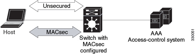
Multiple Host Mode
In standard (not 802.1x REV) 802.1x multiple-host mode, a port is open or closed based on a single authentication. If one user, the primary secured client services client host, is authenticated, the same level of network access is provided to any host connected to the same port. If a secondary host is a MACsec supplicant, it cannot be authenticated and traffic would not flow. A secondary host that is a non-MACsec host can send traffic to the network without authentication because it is in multiple-host mode. The figure shows MACsec in Standard Multiple-Host Unsecure Mode.
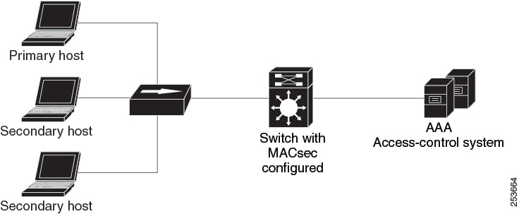
Note |
Multi-host mode is not recommended because after the first successful client, authentication is not required for other clients, which is not secure. |
In standard (not 802.1x REV) 802.1x multiple-domain mode, a port is open or closed based on a single authentication. If the primary user, a PC on data domain, is authenticated, the same level of network access is provided to any domain connected to the same port. If a secondary user is a MACsec supplicant, it cannot be authenticated and traffic would no flow. A secondary user, an IP phone on voice domain, that is a non-MACsec host, can send traffic to the network without authentication because it is in multiple-domain mode.
Multiple-Domain Mode
In standard (not 802.1x REV) 802.1x multiple-domain mode, a port is open or closed based on a single authentication. If the primary user, a PC on data domain, is authenticated, the same level of network access is provided to any domain connected to the same port. If a secondary user is a MACsec supplicant, it cannot be authenticated and traffic would no flow. A secondary user, an IP phone on voice domain, that is a non-MACsec host, can send traffic to the network without authentication because it is in multiple-domain mode.
MKA/MACsec for Port Channel
MKA/MACsec can be configured on the port members of a port channel. MKA/MACsec is agnostic to the port channel since the MKA session is established between the port members of a port channel.
Note |
Etherchannel links that are formed as part of the port channel can either be congruent or disparate i.e. the links can either be MACsec-secured or non-MACsec-secured. MKA session between the port members is established even if a port member on one side of the port channel is not configured with MACsec. |
It is recommended that you enable MKA/MACsec on all the member ports for better security of the port channel.
How to Configure MACsec Encryption
Configuring MKA and MACsec
MACsec is disabled by default. No MKA policies are configured.
Configuring an MKA Policy
SUMMARY STEPS
- enable
- configure terminal
- mka policy policy name
- key-server priority
- include-icv-indicator
- macsec-cipher-suite gcm-aes-128
- confidentiality-offset Offset value
- end
- show mka policy
DETAILED STEPS
| Command or Action | Purpose | |||
|---|---|---|---|---|
|
Step 1 |
enable Example: |
Enables privileged EXEC mode.
|
||
|
Step 2 |
configure terminal Example: |
Enters global configuration mode. |
||
|
Step 3 |
mka policy policy name Example: |
Identifies an MKA policy, and enters MKA policy configuration mode. The maximum policy name length is 16 characters.
|
||
|
Step 4 |
key-server priority Example: |
Configures MKA key server options and set priority (between 0-255).
|
||
|
Step 5 |
include-icv-indicator Example: |
Enables the ICV indicator in MKPDU. Use the no form of this command to disable the ICV indicator — no include-icv-indicator . |
||
|
Step 6 |
macsec-cipher-suite gcm-aes-128 Example: |
Configures cipher suite for deriving SAK with 128-bit encryption. |
||
|
Step 7 |
confidentiality-offset Offset value Example: |
Set the Confidentiality (encryption) offset for each physical interface
|
||
|
Step 8 |
end Example: |
Exit enters MKA policy configuration mode and returns to privileged EXEC mode.
|
||
|
Step 9 |
show mka policy Example: |
Displays MKA policy configuration information.
|
Example
This example configures the MKA policy:
Switch(config)# mka policy mka_policy
Switch(config-mka-policy)# key-server priority 200
Switch(config-mka-policy)# macsec-cipher-suite gcm-aes-128
Switch(config-mka-policy)# confidentiality-offset 30
Switch(config-mka-policy)# end
Configuring MACsec MKA using PSK
SUMMARY STEPS
- enable
- configure terminal
- key chain key-chain-name macsec
- key hex-string
- key-string { [0|6|7] pwd-string | pwd-string}
- lifetime local [start timestamp {hh::mm::ss | day | month | year}] [duration seconds | end timestamp {hh::mm::ss | day | month | year}]
- end
DETAILED STEPS
| Command or Action | Purpose | |||
|---|---|---|---|---|
|
Step 1 |
enable Example: |
Enables privileged EXEC mode.
|
||
|
Step 2 |
configure terminal Example: |
Enters global configuration mode. |
||
|
Step 3 |
key chain key-chain-name macsec Example: |
Configures a key chain and enters the key chain configuration mode. |
||
|
Step 4 |
key hex-string Example: |
Configures a unique identifier for each key in the keychain and enters the keychain's key configuration mode.
|
||
|
Step 5 |
key-string { [0|6|7] pwd-string | pwd-string} Example: |
Sets the password for a key string. Only hex characters must be entered. |
||
|
Step 6 |
lifetime local [start timestamp {hh::mm::ss | day | month | year}] [duration seconds | end timestamp {hh::mm::ss | day | month | year}] Example: |
Sets the lifetime of the pre shared key.
|
||
|
Step 7 |
end Example: |
Exits key chain configuration mode and returns to privileged EXEC mode.
|
Configuring MACsec MKA on an Interface using PSK
SUMMARY STEPS
- enable
- configure terminal
- interface interface-id
- macsec network-link
- mka policy policy-name
- mka pre-shared-key key-chain key-chain name
- macsec replay-protection window-size frame number
- end
DETAILED STEPS
| Command or Action | Purpose | |||
|---|---|---|---|---|
|
Step 1 |
enable Example: |
Enables privileged EXEC mode.
|
||
|
Step 2 |
configure terminal Example: |
Enters global configuration mode. |
||
|
Step 3 |
interface interface-id Example: |
Enters interface configuration mode. |
||
|
Step 4 |
macsec network-link Example: |
Enables MACsec on the interface. |
||
|
Step 5 |
mka policy policy-name Example: |
Configures an MKA policy. |
||
|
Step 6 |
mka pre-shared-key key-chain key-chain name Example: |
Configures an MKA pre-shared-key key-chain name.
|
||
|
Step 7 |
macsec replay-protection window-size frame number Example: |
Sets the MACsec window size for replay protection. |
||
|
Step 8 |
end Example: |
Exits interface configuration mode and returns to privileged EXEC mode.
|
What to do next
-
Disable the existing session by removing macsec network-link configuration on each of the participating node using the no macsec network-link command
-
Configure the MKA policy on the interface on each of the participating node using the mka policy policy-name command.
-
Enable the new session on each of the participating node by using the macsec network-link command.
Configuring MKA MACsec on the Switch-to-host Mode
To configure the MKA MACsec on Switch-to-host mode, perform these steps:
-
Configure dot1x with the SANet including identity control policy.
-
(Optionally) Configure identity control policy with linksec policy.
-
(Optionally) Configure a MKA policy.
-
Apply the macsec on the interface.
-
(Optionally) Apply the configured mka policy on the interface
-
Apply the configured identity control policy on the interface.
Enabling 802.1x Authentication and Configuring AAA
Procedure
| Command or Action | Purpose | |
|---|---|---|
|
Step 1 |
enable Example: |
Enables privileged EXEC mode.
|
|
Step 2 |
configure terminal Example: |
Enters global configuration mode. |
|
Step 3 |
aaa new-model Example: |
Enables AAA. |
|
Step 4 |
aaa authentication dot1x default group group-name Example: |
Sets the default authentication server group for IEEE 802.1x. |
|
Step 5 |
aaa authorization network default group group-name Example: |
Sets the network authorization default group. |
|
Step 6 |
dot1x system-auth-control Example: |
Enables 802.1X on your device. |
|
Step 7 |
aaa group server {radius | tacacs+group-name Example: |
Specifies the name of the RADIUS server configuration for Protected Access Credential (PAC) provisioning and enters RADIUS server configuration mode. |
|
Step 8 |
server name Example: |
Specifies the name of the server configuration for Protected Access Credential (PAC) provisioning and enters RADIUS server configuration mode. |
|
Step 9 |
address ip-address auth-port port-number acct-port port-number Example: |
Configures the IPv4 address for the RADIUS server accounting and authentication parameters. |
|
Step 10 |
key string Example: |
Configures the authentication and encryption key for all RADIUS communications between the device and the RADIUS server. |
|
Step 11 |
policy-map type control subscriber control-policy-name Example: |
Defines a control policy for subscriber sessions and enters control policy-map event configuration mode. |
|
Step 12 |
event event name [ match-all | match-first] Example: |
Specifies the type of event that triggers actions in a control policy if conditions are met.
|
|
Step 13 |
priority-number class { control-class-name | always} [do-all | do-until-failure | do-until-success] Example: |
Specifies that the control class should execute the actions in a control policy, in the specified order, until one of the actions fails, and enters control policy-map action configuration mode. |
|
Step 14 |
action-number authenticate using {dot1x | mab | webauth} [aaa {authc-list authc-list-name | authz-list authz-list-name]} [merge] [parameter-map map-name] [priority priority-number] [replace | replace-all] [retries number {retry-time seconds}] Example: |
(Optional) Initiates the authentication of a subscriber session using the specified method. |
|
Step 15 |
exit |
Returns to global configuration mode. |
|
Step 16 |
interface {type | slot | port} Example: |
Specifies an interface to configure, and enters interface configuration mode. |
|
Step 17 |
switchport mode access vlan vlan id Example: |
Specifies the VLAN for which this access port will carry traffic. If you do not enter this command, the access port carries traffic on VLAN1 only; use this command to change the VLAN for which the access port carries traffic.. |
|
Step 18 |
switchport mode {access | trunk} Example: |
Sets the interface as a nontrunking nontagged single-VLAN Ethernet interface. An access port can carry traffic in one VLAN only. By default, an access port carries traffic for VLAN1. |
|
Step 19 |
access-session closed Example: |
Closes access to a port, preventing clients or devices from gaining network access before authentication is performed. |
|
Step 20 |
access-session port-control {auto | force-authorized | force-unauthorized} Example: |
Enables port-based authentication on the interface. |
|
Step 21 |
dot1x pae [ supplicant| authenticator ] Example: |
Enables port-based authentication on the interface.
|
|
Step 22 |
policy-map type control subscriber control-policy-name Example: |
Defines a control policy for subscriber sessions and enters control policy-map event configuration mode. |
|
Step 23 |
exit |
Returns to global configuration mode. |
Configuring Identity Control Policy with linksec Policy
SUMMARY STEPS
- enable
- configure terminal
- service-template template-name
- linksec policy {must-not-secure | must-secure | should-secure}
- exit
- policy-map type control subscriber control-policy-name
- event authentication-success [ match-all | match-any]
- priority-number class { control-class-name | always} [do-all | do-until-failure | do-until-success]
- action-number activate { policy type control subscriber control-policy-name | service-template template-name [aaa-list list-name] [precedence [replace-all]}
- end
DETAILED STEPS
| Command or Action | Purpose | |
|---|---|---|
|
Step 1 |
enable Example: |
Enables privileged EXEC mode.
|
|
Step 2 |
configure terminal Example: |
Enters global configuration mode. |
|
Step 3 |
service-template template-name Example: |
Defines a template that contains a set of service policy attributes to apply to subscriber sessions and enters service template configuration mode. |
|
Step 4 |
linksec policy {must-not-secure | must-secure | should-secure} Example: |
Sets the link security policy as must-secure.
|
|
Step 5 |
exit Example: |
Exits service template configuration mode and returns to global configuration mode. |
|
Step 6 |
policy-map type control subscriber control-policy-name Example: |
Defines a control policy for subscriber sessions and enters control policy-map event configuration mode. |
|
Step 7 |
event authentication-success [ match-all | match-any] Example: |
Specifies the type of event that triggers actions in a control policy if all authentication events are a match and enters control policy-map class configuration mode. |
|
Step 8 |
priority-number class { control-class-name | always} [do-all | do-until-failure | do-until-success] Example: |
Specifies that the control class should execute the actions in a control policy, in the specified order, until one of the actions fails, and enters control policy-map action configuration mode. |
|
Step 9 |
action-number activate { policy type control subscriber control-policy-name | service-template template-name [aaa-list list-name] [precedence [replace-all]} Example: |
Activates a control policy on a subscriber session. |
|
Step 10 |
end Example: |
Exits control policy-map action configuration mode and enters privileged EXEC mode. |
Configuring MACsec on Switch-to-switch Mode
To configure MACsec on Switch-to-switch mode, perform the following task:
-
Configure a MACsec Pre-Shared Key.
-
(Optionally) configure a MKA policy.
-
Apply the MACsec on the interface.
-
(Optionally) apply the configured MKA policy on the interface.
-
Apply the configured MACsec Pre-Shared Key on the interface.
Configuring MKA Pre-shared Key
Perform the following task to configure MACsec Key Agreement (MKA) pre-shared key.
SUMMARY STEPS
- enable
- configure terminal
- key chain key-chain-name [macsec]
- key hex-string
- cryptographic-algorithm {gcm-aes-128 | gcm-aes-256}
- key-string {[0 | 6] pwd-string | 7 | pwd-string}
- end
DETAILED STEPS
| Command or Action | Purpose | |||
|---|---|---|---|---|
|
Step 1 |
enable Example: |
Enables privileged EXEC mode.
|
||
|
Step 2 |
configure terminal Example: |
Enters global configuration mode. |
||
|
Step 3 |
key chain key-chain-name [macsec] Example: |
Configures a key chain and enters keychain configuration mode |
||
|
Step 4 |
key hex-string Example: |
Configures a key and enters keychain key configuration mode.
|
||
|
Step 5 |
cryptographic-algorithm {gcm-aes-128 | gcm-aes-256} Example: |
Set cryptographic authentication algorithm. |
||
|
Step 6 |
key-string {[0 | 6] pwd-string | 7 | pwd-string} Example: |
Sets the password for a key string. |
||
|
Step 7 |
end Example: |
Returns to privileged EXEC mode. |
Configuring MKA
The MACsec Key Agreement (MKA) enables configuration and control of keying parameters. Perform the following task to configure MKA.
SUMMARY STEPS
- enable
- configure terminal
- mka policy policy-name
- key-server priority key-server-priority
- macsec-cipher-suite {gcm-aes-128 | gcm-aes-256 | gcm-aes-xpn-128 | gcm-aes-xpn-256}
- confidentiality-offset 30
- end
DETAILED STEPS
| Command or Action | Purpose | |||
|---|---|---|---|---|
|
Step 1 |
enable Example: |
Enables privileged EXEC mode.
|
||
|
Step 2 |
configure terminal Example: |
Enters global configuration mode. |
||
|
Step 3 |
mka policy policy-name Example: |
Configures an MKA policy. |
||
|
Step 4 |
key-server priority key-server-priority Example: |
(Optional) Configures MKA key server priority. |
||
|
Step 5 |
macsec-cipher-suite {gcm-aes-128 | gcm-aes-256 | gcm-aes-xpn-128 | gcm-aes-xpn-256} Example: |
(Optional) Configures cipher suite(s) for secure association key (SAK) derivation. Each of the cipher suite options can be repeated only once, but they can be used in any order. |
||
|
Step 6 |
confidentiality-offset 30 Example: |
(Optional) Configures confidentiality offset for MACsec operation. |
||
|
Step 7 |
end Example: |
Returns to privileged EXEC mode.
|
Configuring MACsec and MKA on Interfaces
Perform the following task configure MACsec and MKA on an interface.
SUMMARY STEPS
- enable
- configure terminal
- interface type number
- switchport mode { access | trunk }
- macsec network-link
- mka policy policy-name
- mka pre-shared-key key-chain key-chain-name
- end
DETAILED STEPS
| Command or Action | Purpose | |
|---|---|---|
|
Step 1 |
enable Example: |
Enables privileged EXEC mode.
|
|
Step 2 |
configure terminal Example: |
Enters global configuration mode. |
|
Step 3 |
interface type number Example: |
Enters interface configuration mode. |
|
Step 4 |
switchport mode { access | trunk } Example: |
Sets the switchport mode to trunk. |
|
Step 5 |
macsec network-link Example: |
Enables MKA MACsec on the network link. |
|
Step 6 |
mka policy policy-name Example: |
Configures an MKA policy. |
|
Step 7 |
mka pre-shared-key key-chain key-chain-name Example: |
Configures an MKA pre-shared-key key-chain 10. |
|
Step 8 |
end Example: |
Returns to privileged EXEC mode. |
Configuring MKA/MACsec for Port Channel using PSK
SUMMARY STEPS
- enable
- configure terminal
- interface interface-id
- macsec network-link
- mka policy policy-name
- mka pre-shared-key key-chain key-chain-name
- macsec replay-protection window-size frame number
- channel-group channel-group-number mode {auto | desirable} | {active | passive} | {on}
- end
DETAILED STEPS
| Command or Action | Purpose | |||||||
|---|---|---|---|---|---|---|---|---|
|
Step 1 |
enable Example: |
Enables privileged EXEC mode.
|
||||||
|
Step 2 |
configure terminal Example: |
Enters global configuration mode. |
||||||
|
Step 3 |
interface interface-id Example: |
Enters interface configuration mode. |
||||||
|
Step 4 |
macsec network-link Example: |
Enables MACsec on the interface. Supports layer 2 and layer 3 port channels. |
||||||
|
Step 5 |
mka policy policy-name Example: |
Configures an MKA policy. |
||||||
|
Step 6 |
mka pre-shared-key key-chain key-chain-name Example: |
Configures an MKA pre-shared-key key-chain name.
|
||||||
|
Step 7 |
macsec replay-protection window-size frame number Example: |
Sets the MACsec window size for replay protection. |
||||||
|
Step 8 |
channel-group channel-group-number mode {auto | desirable} | {active | passive} | {on} Example: |
Configures the port in a channel group and sets the mode.
The channel-number range is from 1 to 4096. The port channel associated with this channel group is automatically created if the port channel does not already exist.For mode, select one of the following keywords:
|
||||||
|
Step 9 |
end Example: |
Exits interface configuration mode and returns to privileged EXEC mode.
|
Configuring Port Channel Logical Interfaces for Layer 2 EtherChannels
SUMMARY STEPS
- enable
- configure terminal
- interface port-channel channel-group-number
- switchport
- switchport mode {access | trunk}
- end
DETAILED STEPS
| Command or Action | Purpose | |||
|---|---|---|---|---|
|
Step 1 |
enable Example: |
Enables privileged EXEC mode.
|
||
|
Step 2 |
configure terminal Example: |
Enters global configuration mode. |
||
|
Step 3 |
interface port-channel channel-group-number Example: |
Creates the port channel interface.
|
||
|
Step 4 |
switchport Example: |
Switches an interface that is in Layer 3 mode into Layer 2 mode for Layer 2 configuration. |
||
|
Step 5 |
switchport mode {access | trunk} Example: |
Assigns all ports as static-access ports in the same VLAN, or configure them as trunks. |
||
|
Step 6 |
end Example: |
Exits interface configuration mode and returns to privileged EXEC mode.
|
Configuring Examples for MACsec Encryption
Example: Configuring MKA and MACsec
Device> enable
Device# configure terminal
Device(config)# mka policy mka_policy
Device(config-mka-policy)# key-server priority 200
Device(config-mka-policy)# macsec-cipher-suite gcm-aes-128
Device(config-mka-policy)# confidentiality-offset 30
Device(config-mka-policy)# ssci-based-on-sci
Device(config-mka-policy)#end
Device> enable
Device# configure terminal
Device(config)# interface GigabitEthernet 1/0/1
Device(config-if)# switchport access vlan 17
Device(config-if)# switchport mode access
Device(config-if)# macsec
Device(config-if)# access-session host-mode single-host
Device(config-if)# access-session closed
Device(config-if)# access-session port-control auto
Device(config-if)#mka policy mka_policy
Device(config-if)# dot1x pae authenticator
Device(config-if)#service-policy type control subscriber POLICY_SHOULDSECURE
Device(config-if)#end
Examples: Configuring MACsec MKA using PSK
Device> enable
Device# configure terminal
Device(config)# Key chain keychain1 macsec
Device(config-key-chain)# key 1000
Device(config-keychain-key)# cryptographic-algorithm gcm-aes-128
Device(config-keychain-key)# key-string 12345678901234567890123456789012
Device(config-keychain-key)# lifetime local 12:12:00 July 28 2016 12:19:00 July 28 2016
Device(config-keychain-key)# end
Device> enable
Device# configure terminal
Device(config)# interface GigabitEthernet 0/0/0
Device(config-if)# mka policy mka_policy
Device(config-if)# mka pre-shared-key key-chain key-chain-name
Device(config-if)# macsec replay-protection window-size 10
Device(config-if)# end
Example: Configuring MACsec MKA for Port Channel using PSK
Etherchannel Mode — Static/On
The following is sample configuration on Device 1 and Device 2 with EtherChannel Mode on:
Device> enable
Device# configure terminal
Device(config)# key chain KC macsec
Device(config-key-chain)# key 1000
Device(config-key-chain)# cryptographic-algorithm aes-128-cmac
Device(config-key-chain)# key-string FC8F5B10557C192F03F60198413D7D45
Device(config-key-chain)# exit
Device(config)# mka policy POLICY
Device(config-mka-policy)# key-server priority 0
Device(config-mka-policy)# macsec-cipher-suite gcm-aes-128
Device(config-mka-policy)# confidentiality-offset 0
Device(config-mka-policy)# exit
Device(config)# interface gigabitethernet 1/0/1
Device(config-if)# channel-group 2 mode on
Device(config-if)# macsec network-link
Device(config-if)# mka policy POLICY
Device(config-if)# mka pre-shared-key key-chain KC
Device(config-if)# exit
Device(config)# interface gigabitethernet 1/0/2
Device(config-if)# channel-group 2 mode on
Device(config-if)# macsec network-link
Device(config-if)# mka policy POLICY
Device(config-if)# mka pre-shared-key key-chain KC
Device(config-if)# end
Layer 2 EtherChannel Configuration
Device 1
Device> enable
Device# configure terminal
Device(config)# interface port-channel 2
Device(config-if)# switchport
Device(config-if)# switchport mode trunk
Device(config-if)# no shutdown
Device(config-if)# end
Device 2
Device> enable
Device# configure terminal
Device(config)# interface port-channel 2
Device(config-if)# switchport
Device(config-if)# switchport mode trunk
Device(config-if)# no shutdown
Device(config-if)# end
	Flags:  D - down        P - bundled in port-channel
        I - stand-alone s - suspended
        H - Hot-standby (LACP only)
        R - Layer3      S - Layer2
        U - in use      f - failed to allocate aggregator

        M - not in use, minimum links not met
        u - unsuitable for bundling
        w - waiting to be aggregated
        d - default port

        A - formed by Auto LAG


	Number of channel-groups in use: 1
	Number of aggregators:           1

	Group  Port-channel  Protocol    Ports
	------+-------------+-----------+-----------------------------------------------
	2      Po2(RU)          -        Te1/0/1(P)  Te1/0/2(P)
Etherchannel Mode — LACP
The following is sample configuration on Device 1 and Device 2 with EtherChannel Mode as LACP.
Device> enable
Device# configure terminal
Device(config)# key chain KC macsec
Device(config-key-chain)# key 1000
Device(config-key-chain)# cryptographic-algorithm aes-128-cmac
Device(config-key-chain)# key-string FC8F5B10557C192F03F60198413D7D45
Device(config-key-chain)# exit
Device(config)# mka policy POLICY
Device(config-mka-policy)# key-server priority 0
Device(config-mka-policy)# macsec-cipher-suite gcm-aes-128
Device(config-mka-policy)# confidentiality-offset 0
Device(config-mka-policy)# exit
Device(config)# interface gigabitethernet 1/0/1
Device(config-if)# channel-group 2 mode active
Device(config-if)# macsec network-link
Device(config-if)# mka policy POLICY
Device(config-if)# mka pre-shared-key key-chain KC
Device(config-if)# exit
Device(config)# interface gigabitethernet 1/0/2
Device(config-if)# channel-group 2 mode active
Device(config-if)# macsec network-link
Device(config-if)# mka policy POLICY
Device(config-if)# mka pre-shared-key key-chain KC
Device(config-if)# end
Layer 2 EtherChannel Configuration
Device 1
Device> enable
Device# configure terminal
Device(config)# interface port-channel 2
Device(config-if)# switchport
Device(config-if)# switchport mode trunk
Device(config-if)# no shutdown
Device(config-if)# end
Device 2
Device> enable
Device# configure terminal
Device(config)# interface port-channel 2
Device(config-if)# switchport
Device(config-if)# switchport mode trunk
Device(config-if)# no shutdown
Device(config-if)# end Flags: D - down P - bundled in port-channel
I - stand-alone s - suspended
H - Hot-standby (LACP only)
R - Layer3 S - Layer2
U - in use f - failed to allocate aggregator
M - not in use, minimum links not met
u - unsuitable for bundling
w - waiting to be aggregated
d - default port
A - formed by Auto LAG
Number of channel-groups in use: 1
Number of aggregators: 1
------+-------------+-----------+-----------------------------------------------
2 Po2(SU) LACP Te1/1/1(P) Te1/1/2(P)
	Flags:  D - down        P - bundled in port-channel
        I - stand-alone s - suspended
        H - Hot-standby (LACP only)
        R - Layer3      S - Layer2
        U - in use      f - failed to allocate aggregator

        M - not in use, minimum links not met
        u - unsuitable for bundling
        w - waiting to be aggregated
        d - default port

        A - formed by Auto LAG


	Number of channel-groups in use: 1
	Number of aggregators:           1

	Group  Port-channel  Protocol    Ports
	------+-------------+-----------+-----------------------------------------------
	2      Po2(RU)         LACP      Te1/1/1(P)  Te1/1/2(P)
Etherchannel Mode — PAgP
The following is sample configuration on Device 1 and Device 2 with EtherChannel Mode as PAgP:
Device> enable
Device# configure terminal
Device(config)# key chain KC macsec
Device(config-key-chain)# key 1000
Device(config-key-chain)# cryptographic-algorithm aes-128-cmac
Device(config-key-chain)# key-string FC8F5B10557C192F03F60198413D7D45
Device(config-key-chain)# exit
Device(config)# mka policy POLICY
Device(config-mka-policy)# key-server priority 0
Device(config-mka-policy)# macsec-cipher-suite gcm-aes-128
Device(config-mka-policy)# confidentiality-offset 0
Device(config-mka-policy)# exit
Device(config)# interface gigabitethernet 1/0/1
Device(config-if)# channel-group 2 mode desirable
Device(config-if)# macsec network-link
Device(config-if)# mka policy POLICY
Device(config-if)# mka pre-shared-key key-chain KC
Device(config-if)# exit
Device(config)# interface gigabitethernet 1/0/2
Device(config-if)# channel-group 2 mode desirable
Device(config-if)# macsec network-link
Device(config-if)# mka policy POLICY
Device(config-if)# mka pre-shared-key key-chain KC
Device(config-if)# end
Layer 2 EtherChannel Configuration
Device 1
Device> enable
Device# configure terminal
Device(config)# interface port-channel 2
Device(config-if)# switchport
Device(config-if)# switchport mode trunk
Device(config-if)# no shutdown
Device(config-if)# end
Device 2
Device> enable
Device# configure terminal
Device(config)# interface port-channel 2
Device(config-if)# switchport
Device(config-if)# switchport mode trunk
Device(config-if)# no shutdown
Device(config-if)# end Flags: D - down P - bundled in port-channel
I - stand-alone s - suspended
H - Hot-standby (LACP only)
R - Layer3 S - Layer2
U - in use f - failed to allocate aggregator
M - not in use, minimum links not met
u - unsuitable for bundling
w - waiting to be aggregated
d - default port
A - formed by Auto LAG
Number of channel-groups in use: 1
Number of aggregators: 1
------+-------------+-----------+-----------------------------------------------
2 Po2(SU) PAgP Te1/1/1(P) Te1/1/2(P)
	Flags:  D - down        P - bundled in port-channel
        I - stand-alone s - suspended
        H - Hot-standby (LACP only)
        R - Layer3      S - Layer2
        U - in use      f - failed to allocate aggregator

        M - not in use, minimum links not met
        u - unsuitable for bundling
        w - waiting to be aggregated
        d - default port

        A - formed by Auto LAG


	Number of channel-groups in use: 1
	Number of aggregators:           1

	Group  Port-channel  Protocol    Ports
	------+-------------+-----------+-----------------------------------------------
	2      Po2(RU)         PAgP      Te1/1/1(P)  Te1/1/2(P)
Displaying Active MKA Sessions
Device# show mka sessions interface Te1/0/1

===============================================================================
Interface      Local-TxSCI         Policy-Name      Inherited         Key-Server
Port-ID        Peer-RxSCI          MACsec-Peers     Status            CKN
=========================================================================================
Te1/0/1        00a3.d144.3364/0025 POLICY           NO                NO
37             701f.539b.b0c6/0032 1                Secured           1000
Example: Displaying MKA Information
Device# show mka sessions


Total MKA Sessions....... 1
      Secured Sessions... 1
      Pending Sessions... 0

====================================================================================================
Interface      Local-TxSCI         Policy-Name      Inherited         Key-Server
Port-ID        Peer-RxSCI          MACsec-Peers     Status            CKN
====================================================================================================
Gi1/0/1        204c.9e85.ede4/002b p2               NO                YES
43             c800.8459.e764/002a 1                Secured           0100000000000000000000000000000000000000000000000000000000000000
Device# show mka sessions interface GigabitEthernet 1/0/1

Summary of All Currently Active MKA Sessions on Interface GigabitEthernet1/0/1...

====================================================================================================
Interface      Local-TxSCI         Policy-Name      Inherited         Key-Server
Port-ID        Peer-RxSCI          MACsec-Peers     Status            CKN
====================================================================================================
Gi1/0/1        204c.9e85.ede4/002b p2               NO                YES
43             c800.8459.e764/002a 1                Secured           0100000000000000000000000000000000000000000000000000000000000000
Device# show mka sessions interface GigabitEthernet 1/0/1 detail


MKA Detailed Status for MKA Session
===================================
Status: SECURED - Secured MKA Session with MACsec

Local Tx-SCI............. 204c.9e85.ede4/002b
Interface MAC Address.... 204c.9e85.ede4
MKA Port Identifier...... 43
Interface Name........... GigabitEthernet1/0/1
Audit Session ID.........
CAK Name (CKN)........... 0100000000000000000000000000000000000000000000000000000000000000
Member Identifier (MI)... D46CBEC05D5D67594543CEAE
Message Number (MN)...... 89567
EAP Role................. NA
Key Server............... YES
MKA Cipher Suite......... AES-128-CMAC

Latest SAK Status........ Rx & Tx
Latest SAK AN............ 0
Latest SAK KI (KN)....... D46CBEC05D5D67594543CEAE00000001 (1)
Old SAK Status........... FIRST-SAK
Old SAK AN............... 0
Old SAK KI (KN).......... FIRST-SAK (0)

SAK Transmit Wait Time... 0s (Not waiting for any peers to respond)
SAK Retire Time.......... 0s (No Old SAK to retire)

MKA Policy Name.......... p2
Key Server Priority...... 2
Delay Protection......... NO
Replay Protection........ YES
Replay Window Size....... 0
Confidentiality Offset... 0
Algorithm Agility........ 80C201
Send Secure Announcement.. DISABLED
SAK Cipher Suite......... 0080C20001000001 (GCM-AES-128)
MACsec Capability........ 3 (MACsec Integrity, Confidentiality, & Offset)
MACsec Desired........... YES

# of MACsec Capable Live Peers............ 1
# of MACsec Capable Live Peers Responded.. 1

Live Peers List:
  MI                        MN          Rx-SCI (Peer)        KS Priority
  ----------------------------------------------------------------------
  38046BA37D7DA77E06D006A9  89555       c800.8459.e764/002a   10

Potential Peers List:
  MI                        MN          Rx-SCI (Peer)        KS Priority
  ----------------------------------------------------------------------

Dormant Peers List:
  MI                        MN          Rx-SCI (Peer)        KS Priority
  ----------------------------------------------------------------------
Device# show mka sessions details

MKA Detailed Status for MKA Session
===================================
Status: SECURED - Secured MKA Session with MACsec

Local Tx-SCI............. 204c.9e85.ede4/002b
Interface MAC Address.... 204c.9e85.ede4
MKA Port Identifier...... 43
Interface Name........... GigabitEthernet1/0/1
Audit Session ID.........
CAK Name (CKN)........... 0100000000000000000000000000000000000000000000000000000000000000
Member Identifier (MI)... D46CBEC05D5D67594543CEAE
Message Number (MN)...... 89572
EAP Role................. NA
Key Server............... YES
MKA Cipher Suite......... AES-128-CMAC

Latest SAK Status........ Rx & Tx
Latest SAK AN............ 0
Latest SAK KI (KN)....... D46CBEC05D5D67594543CEAE00000001 (1)
Old SAK Status........... FIRST-SAK
Old SAK AN............... 0
Old SAK KI (KN).......... FIRST-SAK (0)

SAK Transmit Wait Time... 0s (Not waiting for any peers to respond)
SAK Retire Time.......... 0s (No Old SAK to retire)

MKA Policy Name.......... p2
Key Server Priority...... 2
Delay Protection......... NO
Replay Protection........ YES
Replay Window Size....... 0
Confidentiality Offset... 0
Algorithm Agility........ 80C201
Send Secure Announcement.. DISABLED
SAK Cipher Suite......... 0080C20001000001 (GCM-AES-128)
MACsec Capability........ 3 (MACsec Integrity, Confidentiality, & Offset)
MACsec Desired........... YES

# of MACsec Capable Live Peers............ 1
# of MACsec Capable Live Peers Responded.. 1

Live Peers List:
  MI                        MN          Rx-SCI (Peer)        KS Priority
  ----------------------------------------------------------------------
  38046BA37D7DA77E06D006A9  89560       c800.8459.e764/002a   10

Potential Peers List:
  MI                        MN          Rx-SCI (Peer)        KS Priority
  ----------------------------------------------------------------------

Dormant Peers List:
  MI                        MN          Rx-SCI (Peer)        KS Priority
  ----------------------------------------------------------------------
Device# show mka policy


MKA Policy Summary...

Policy            KS       Delay   Replay  Window Conf   Cipher          Interfaces
Name              Priority Protect Protect Size   Offset Suite(s)        Applied
======================================================================================================
*DEFAULT POLICY*  0        FALSE   TRUE    0      0      GCM-AES-128

p1                1        FALSE   TRUE    0      0      GCM-AES-128

p2 2 FALSE TRUE 0 0 GCM-AES-128 Gi1/0/1Device# show mka policy p2
MKA Policy Summary...
Policy KS Delay Replay Window Conf Cipher Interfaces
Name Priority Protect Protect Size Offset Suite(s) Applied
======================================================================================================
p2 2 FALSE TRUE 0 0 GCM-AES-128 Gi1/0/1Device# show mka policy p2 detail
MKA Policy Configuration ("p2")
========================
MKA Policy Name........ p2
Key Server Priority.... 2
Confidentiality Offset. 0
Send Secure Announcement..DISABLED
Cipher Suite(s)........ GCM-AES-128
Applied Interfaces...
GigabitEthernet1/0/1Device# show mka statistics interface GigabitEthernet 1/0/1
MKA Statistics for Session
==========================
Reauthentication Attempts.. 0
CA Statistics
Pairwise CAKs Derived... 0
Pairwise CAK Rekeys..... 0
Group CAKs Generated.... 0
Group CAKs Received..... 0
SA Statistics
SAKs Generated.......... 1
SAKs Rekeyed............ 0
SAKs Received........... 0
SAK Responses Received.. 1
MKPDU Statistics
MKPDUs Validated & Rx... 89585
"Distributed SAK".. 0
"Distributed CAK".. 0
MKPDUs Transmitted...... 89596
"Distributed SAK".. 1
"Distributed CAK".. 0
Device# show mka summary

Total MKA Sessions....... 1
      Secured Sessions... 1
      Pending Sessions... 0

====================================================================================================
Interface      Local-TxSCI         Policy-Name      Inherited         Key-Server
Port-ID        Peer-RxSCI          MACsec-Peers     Status            CKN
====================================================================================================
Gi1/0/1        204c.9e85.ede4/002b p2               NO                YES
43             c800.8459.e764/002a 1                Secured           0100000000000000000000000000000000000000000000000000000000000000


MKA Global Statistics
=====================
MKA Session Totals
   Secured.................... 1
   Reauthentication Attempts.. 0

   Deleted (Secured).......... 0
   Keepalive Timeouts......... 0

CA Statistics
   Pairwise CAKs Derived...... 0
   Pairwise CAK Rekeys........ 0
   Group CAKs Generated....... 0
   Group CAKs Received........ 0

SA Statistics
   SAKs Generated............. 1
   SAKs Rekeyed............... 0
   SAKs Received.............. 0
   SAK Responses Received..... 1

MKPDU Statistics
   MKPDUs Validated & Rx...... 89589
      "Distributed SAK"..... 0
      "Distributed CAK"..... 0
   MKPDUs Transmitted......... 89600
      "Distributed SAK"..... 1
      "Distributed CAK"..... 0

MKA Error Counter Totals
========================
Session Failures
   Bring-up Failures................ 0
   Reauthentication Failures........ 0
   Duplicate Auth-Mgr Handle........ 0

SAK Failures
   SAK Generation................... 0
   Hash Key Generation.............. 0
   SAK Encryption/Wrap.............. 0
   SAK Decryption/Unwrap............ 0
   SAK Cipher Mismatch.............. 0

CA Failures
   Group CAK Generation............. 0
   Group CAK Encryption/Wrap........ 0
   Group CAK Decryption/Unwrap...... 0
   Pairwise CAK Derivation.......... 0
   CKN Derivation................... 0
   ICK Derivation................... 0
   KEK Derivation................... 0
   Invalid Peer MACsec Capability... 0
MACsec Failures
   Rx SC Creation................... 0
   Tx SC Creation................... 0
   Rx SA Installation............... 0
   Tx SA Installation............... 0

MKPDU Failures
   MKPDU Tx......................... 0
   MKPDU Rx Validation.............. 0
   MKPDU Rx Bad Peer MN............. 0
   MKPDU Rx Non-recent Peerlist MN.. 0
IPv6 First Hop Security Overview
First Hop Security in IPv6 (FHS IPv6) is a set of IPv6 security features, whose policies can be attached to a physical interface, an EtherChannel interface, or a VLAN. An IPv6 software policy database service stores and accesses these policies. When a policy is configured or modified, the attributes of the policy are stored or updated in the software policy database, and applied as specified. The following IPv6 policies are currently supported:
-
Manual IPv6 Binding—Creates static IPv6 binding for secure network.
-
IPv6 Address Glean/Inspect/Guard—Allows to build dynamic binding table by NDP and DHCPv6 glean. Also, inspects control packets to prevent unauthorized messages by rogue host, and guard unauthorized RA and DHCP server messages.
-
IPv6 Device Tracking—IPv6 Device Tracking allows to track the presence, location, and movement of end-nodes in the network. SISF snoops traffic received by the switch ports, extracts device identity (MAC and IP address), and stores them in a binding table. Many features, such as, Cisco TrustSec, IEEE 802.1X, LISP, and web authentication depend on the accuracy of this information to operate properly.
-
IPv6 FHS Binding Recory—IPv6 binding address recovery allows to recover binding table from a complete failure of the router. When the traffic is received from a an unknow source that is not in the binding table, IPv6 FHS Binding Recory feature helps to rebuild binding table based on IPv6 address glean by NDP or DHCPv6 recovery.
-
IPv6 Source Guard—Like IPv4 Source Guard, IPv6 Source Guard validates the source address or prefix to prevent source address spoofing.
A source guard programs the hardware to allow or deny traffic based on source or destination addresses. It deals exclusively with data packet traffic.
The IPv6 source guard feature provides the ability to store entries in the hardware TCAM table to prevent a host from sending packets with an invalid IPv6 source address.
To debug source-guard packets, use the debug device-tracking source-guard privileged EXEC command.
Note
The IPv6 Source Guard feature is supported only in the ingress direction and not supported in the egress direction. The IPv6 Prefix Guard is not supported.
-
IPv6 DHCP Guard—The IPv6 DHCP Guard feature blocks reply and advertisement messages that come from unauthorized DHCPv6 servers and relay agents. IPv6 DHCP guard can prevent forged messages from being entered in the binding table and block DHCPv6 server messages when they are received on ports that are not explicitly configured as facing a DHCPv6 server or DHCP relay. To use this feature, configure a policy and attach it to an interface or a VLAN.
-
IPv6 Router Advertisement Guard—The IPv6 Router Advertisement (RA) guard feature enables the network administrator to block or reject unwanted or rogue RA guard messages that arrive at the network device platform. RAs are used by devices to announce themselves on the link. The RA Guard feature analyzes the RAs and filters out bogus RAs sent by unauthorized devices. In host mode, all router advertisement and router redirect messages are disallowed on the port. The RA guard feature compares configuration information on the Layer 2 device with the information found in the received RA frame. Once the Layer 2 device has validated the content of the RA frame and router redirect frame against the configuration, it forwards the RA to its unicast or multicast destination. If the RA frame content is not validated, the RA is dropped.
Configuring the Manual IPv6 Binding
Beginning in privileged EXEC mode, follow these steps to configure IPv6 Binding Table Content :
SUMMARY STEPS
- enable
- configure terminal
- device-tracking binding vlan vlan-id {ipv6-address interface interface {mac_address} [tracking{ [default | disable] [ reachable-lifetimevalue [seconds | default | infinite] | [enable [reachable-lifetimevalue [seconds | default | infinite] }
- exit
- show device-tracking binding
DETAILED STEPS
| Command or Action | Purpose | |
|---|---|---|
|
Step 1 |
enable Example: |
Enables privileged EXEC mode. Enter your password if prompted. |
|
Step 2 |
configure terminal Example: |
Enters global configuration mode. |
|
Step 3 |
device-tracking binding vlan vlan-id {ipv6-address interface interface {mac_address} [tracking{ [default | disable] [ reachable-lifetimevalue [seconds | default | infinite] | [enable [reachable-lifetimevalue [seconds | default | infinite] } Example: |
Adds a static entry to the binding table database. |
|
Step 4 |
exit Example: |
Exits global configuration mode and returns to privileged EXEC mode. |
|
Step 5 |
show device-tracking binding Example: |
Displays contents of a binding table. |
Configuring the IPv6 Binding Recovery
Beginning in privileged EXEC mode, follow these steps to configure IPv6 Binding Recovery:
SUMMARY STEPS
- enable
- configure terminal
- device-tracking policy policy-name
- data-glean recovery {dhcp | ndp [dhcp] }
- data-glean log-only
- exit
DETAILED STEPS
| Command or Action | Purpose | |
|---|---|---|
|
Step 1 |
enable Example: |
Enables privileged EXEC mode. Enter your password if prompted. |
|
Step 2 |
configure terminal Example: |
Enters global configuration mode. |
|
Step 3 |
device-tracking policy policy-name Example: |
Creates a device tracking policy and enters IPv6 device-tracking policy configuration mode. |
|
Step 4 |
data-glean recovery {dhcp | ndp [dhcp] } Example: |
Enables data address gleaning, validates messages against various criteria, specifies the security level for messages. |
|
Step 5 |
data-glean log-only Example: |
Enables IPv6 first-hop security binding table recovery using source (or “data”) address gleaning. |
|
Step 6 |
exit Example: |
Exits global configuration mode and returns to privileged EXEC mode. |
Configuring an IPv6 Neighbor Discovery Inspection Policy
Beginning in privileged EXEC mode, follow these steps to configure an IPv6 ND Inspection Policy:
SUMMARY STEPS
- enable
- configure terminal
- device-tracking policy policy-name
- security-level inspect
- device-role {host | switch}
- limit address-count value
- trusted-port
- end
- show device-tracking policy example_policy
DETAILED STEPS
| Command or Action | Purpose | |
|---|---|---|
|
Step 1 |
enable Example: |
Enables privileged EXEC mode. Enter your password if prompted. |
|
Step 2 |
configure terminal Example: |
Enters global configuration mode. |
|
Step 3 |
device-tracking policy policy-name Example: |
Creates the policy and enters the device-tracking configuration mode. |
|
Step 4 |
security-level inspect Example: |
Specifies the level of security enforced by the feature. |
|
Step 5 |
device-role {host | switch} Example: |
Specifies the role of the device attached to the port. The default is host. |
|
Step 6 |
limit address-count value Example: |
Limits the number of IPv6 addresses allowed to be used on the port. |
|
Step 7 |
trusted-port Example: |
Configures a port to become a trusted port. |
|
Step 8 |
end Example: |
Exits ND Inspection Policy configuration mode and returns to privileged EXEC mode. |
|
Step 9 |
show device-tracking policy example_policy Example: |
Verifies the device-tracking inspection configuration. |
Configuring an IPv6 Device Tracking Policy
Note |
The IPv6 Snooping Policy feature has been deprecated. Although the commands are visible on the CLI and you can configure them, we recommend that you use the Switch Integrated Security Feature (SISF)-based Device Tracking feature instead. |
Beginning in privileged EXEC mode, follow these steps to configure device tracking policy :
SUMMARY STEPS
- enable
- configure terminal
- device-tracking policy policy-name
- {[default ] | [device-role {node | switch}] | [limit address-count value] | [no] | [protocol {dhcp | dhcp 6 | arp ndp} ] | [security-level {glean | guard | inspect} ] | [tracking {disable [stale-lifetime [seconds | infinite] | enable [reachable-lifetime [seconds | infinite] } ] | [trusted-port ] }
- end
- show device-tracking policy policy-name
DETAILED STEPS
| Command or Action | Purpose | |
|---|---|---|
|
Step 1 |
enable Example: |
Enables privileged EXEC mode. Enter your password if prompted. |
|
Step 2 |
configure terminal Example: |
Enters global configuration mode. |
|
Step 3 |
device-tracking policy policy-name Example: |
Creates a device tracking policy and enters IPv4 or IPv6 device-tracking policy configuration mode. |
|
Step 4 |
{[default ] | [device-role {node | switch}] | [limit address-count value] | [no] | [protocol {dhcp | dhcp 6 | arp ndp} ] | [security-level {glean | guard | inspect} ] | [tracking {disable [stale-lifetime [seconds | infinite] | enable [reachable-lifetime [seconds | infinite] } ] | [trusted-port ] } Example:Example: |
Enables data address gleaning, validates messages against various criteria, specifies the security level for messages.
|
|
Step 5 |
end Example: |
Exits IPv6 snooping policy configuration mode and returns to privileged EXEC mode. |
|
Step 6 |
show device-tracking policy policy-name Example: |
Displays the device-tracking policy policy configuration. |
What to do next
Attach an IPv6 device-tracking policy to interfaces or VLANs.
Attaching an IPv6 Device Tracking Policy to an Interface
Beginning in privileged EXEC mode, follow these steps to attach an IPv6 device tracking policy on an interface or VLAN:
SUMMARY STEPS
- enable
- configure terminal
- interface interface_type stack/module/port
- device-tracking [attach-policy policy_name [ vlan {vlan_id | add vlan_ids | except vlan_ids | none | remove vlan_ids}] | vlan {vlan_id | add vlan_ids | except vlan_ids | none | remove vlan_ids | all} ]
- end
- show running-config
DETAILED STEPS
| Command or Action | Purpose | |
|---|---|---|
|
Step 1 |
enable Example: |
Enables privileged EXEC mode. Enter your password if prompted. |
|
Step 2 |
configure terminal Example: |
Enters global configuration mode. |
|
Step 3 |
interface interface_type stack/module/port Example: |
Specifies an interface type and identifier and enters the interface configuration mode. |
|
Step 4 |
device-tracking [attach-policy policy_name [ vlan {vlan_id | add vlan_ids | except vlan_ids | none | remove vlan_ids}] | vlan {vlan_id | add vlan_ids | except vlan_ids | none | remove vlan_ids | all} ] Example: |
Attaches a custom IPv6 snooping policy to the interface or the specified VLANs on the interface. To attach the default policy to the interface, use the device-traking command without the attach-policy keyword. To attach the default policy to VLANs on the interface, use the device-traking vlan command. The default policy is, security-level guard, device-role node, protocol ndp and dhcp. |
|
Step 5 |
end Example: |
Exits interface configuration mode and returns to privileged EXEC mode. |
|
Step 6 |
show running-config Example: |
Verifies that the policy is attached to the specified interface without exiting the interface configuration mode. |
Attaching an IPv6 Device Tracking Policy to VLANs Globally
Beginning in privileged EXEC mode, follow these steps to attach an IPv6 device-tracing policy to VLANs across multiple interfaces:
SUMMARY STEPS
- enable
- configure terminal
- vlan configuration vlan_list
- device-traking [attach-policy policy_name]
- end
DETAILED STEPS
| Command or Action | Purpose | |
|---|---|---|
|
Step 1 |
enable Example: |
Enables privileged EXEC mode. Enter your password if prompted. |
|
Step 2 |
configure terminal Example: |
Enters global configuration mode. |
|
Step 3 |
vlan configuration vlan_list Example: |
Specifies the VLANs to which the IPv6 Snooping policy will be attached, and enters the VLAN interface configuration mode. |
|
Step 4 |
device-traking [attach-policy policy_name] Example: |
Attaches the IPv6 Snooping policy to the specified VLANs across all device interfaces. The default policy is attached if the attach-policy option is not used. The default policy is, security-level guard, device-role node, protocol ndp and dhcp. |
|
Step 5 |
end Example: |
Exits VLAN interface configuration mode and returns to privileged EXEC mode. |
Configuring IPv6 Source Guard
SUMMARY STEPS
- enable
- configure terminal
- ipv6 source-guard policy policy_name
- validate address
- end
- show ipv6 source-guard policy policy_name
DETAILED STEPS
| Command or Action | Purpose | |
|---|---|---|
|
Step 1 |
enable Example: |
Enables privileged EXEC mode. Enter your password, if prompted. |
|
Step 2 |
configure terminal Example: |
Enters global configuration mode. |
|
Step 3 |
ipv6 source-guard policy policy_name Example: |
Specifies the IPv6 Source Guard policy name and enters IPv6 Source Guard policy configuration mode. |
|
Step 4 |
validate address Example: |
Enables the validate address feature. This feature does not support the validate prefix and no validate options. |
|
Step 5 |
end Example: |
Exits of IPv6 Source Guard policy configuration mode and returns to privileged EXEC mode. |
|
Step 6 |
show ipv6 source-guard policy policy_name Example: |
Shows the policy configuration and all the interfaces where the policy is applied. |
What to do next
Apply the IPv6 Source Guard policy to an interface.
Attaching an IPv6 Source Guard Policy to an Interface
SUMMARY STEPS
- enable
- configure terminal
- interface type number
- ipv6 source-guard [ attach-policy <policy_name> ]
- end
- show ipv6 source-guard policy policy_name
DETAILED STEPS
| Command or Action | Purpose | |
|---|---|---|
|
Step 1 |
enable Example: |
Enables privileged EXEC mode. Enter your password, if prompted. |
|
Step 2 |
configure terminal Example: |
Enters global configuration mode. |
|
Step 3 |
interface type number Example: |
Specifies an interface type and identifier; enters interface configuration mode. |
|
Step 4 |
ipv6 source-guard [ attach-policy <policy_name> ] Example: |
Attaches the IPv6 Source Guard policy to the interface. The default policy is attached if the attach-policy option is not used. |
|
Step 5 |
end Example: |
Exits interface configuration mode and returns to privileged EXEC mode. |
|
Step 6 |
show ipv6 source-guard policy policy_name Example: |
Shows the policy configuration and all the interfaces where the policy is applied. |
Configuring an IPv6 DHCP Guard Policy
Beginning in privileged EXEC mode, follow these steps to configure an IPv6 DHCP (DHCPv6) Guard policy:
SUMMARY STEPS
- enable
- configure terminal
- ipv6 dhcp guard policy policy-name
- device-role {client | monitor |server}
- trusted-port
- end
- show ipv6 dhcp guard policy policy_name
DETAILED STEPS
| Command or Action | Purpose | |||
|---|---|---|---|---|
|
Step 1 |
enable Example: |
Enables privileged EXEC mode. Enter your password, if prompted. |
||
|
Step 2 |
configure terminal Example: |
Enters global configuration mode. |
||
|
Step 3 |
ipv6 dhcp guard policy policy-name Example: |
Specifies the DHCPv6 Guard policy name and enters DHCPv6 Guard Policy configuration mode. |
||
|
Step 4 |
device-role {client | monitor |server} Example: |
(Optional) Filters out DHCPv6 replies and DHCPv6 advertisements on the port that are not from a device of the specified role. Default is client.
|
||
|
Step 5 |
trusted-port Example: |
(Optional) trusted-port—Sets the port to a trusted mode. No further policing takes place on the port.
|
||
|
Step 6 |
end Example: |
Exits DHCPv6 Guard Policy configuration mode and returns to privileged EXEC mode. |
||
|
Step 7 |
show ipv6 dhcp guard policy policy_name Example: |
(Optional) Displays the configuration of the IPv6 DHCP guard policy. Omitting the policy_name variable displays all DHCPv6 policies. |
Attaching an IPv6 DHCP Guard Policy to an Interface or a VLAN on an Interface
Beginning in privileged EXEC mode, follow these steps to configure IPv6 Binding Table Content :
SUMMARY STEPS
- enable
- configure terminal
- interface type number
- ipv6 dhcp guard [attach-policy policy_name [ vlan {vlan_ids | add vlan_ids | except vlan_ids | none | remove vlan_ids | all} ] | vlan [ {vlan_ids | add vlan_ids | exceptvlan_ids | none | remove vlan_ids | all} ]
- end
DETAILED STEPS
| Command or Action | Purpose | |
|---|---|---|
|
Step 1 |
enable Example: |
Enables privileged EXEC mode. Enter your password, if prompted. |
|
Step 2 |
configure terminal Example: |
Enters global configuration mode. |
|
Step 3 |
interface type number Example: |
Specifies an interface type and identifier, and enters interface configuration mode. |
|
Step 4 |
ipv6 dhcp guard [attach-policy policy_name [ vlan {vlan_ids | add vlan_ids | except vlan_ids | none | remove vlan_ids | all} ] | vlan [ {vlan_ids | add vlan_ids | exceptvlan_ids | none | remove vlan_ids | all} ] Example: |
Attaches the DHCP Guard policy to the interface or the specified VLANs on that interface. The default policy is attached if the attach-policy option is not used. |
|
Step 5 |
end Example: |
Exits interface configuration mode and returns to privileged EXEC mode. |
Attaching an IPv6 DHCP Guard Policy to VLANs Globally
Beginning in privileged EXEC mode, follow these steps to attach an IPv6 DHCP Guard policy to VLANs across multiple interfaces:
SUMMARY STEPS
- enable
- configure terminal
- vlan configuration vlan_list
- ipv6 dhcp guard [attach-policy policy_name]
- end
DETAILED STEPS
| Command or Action | Purpose | |
|---|---|---|
|
Step 1 |
enable Example: |
Enables privileged EXEC mode. Enter your password, if prompted. |
|
Step 2 |
configure terminal Example: |
Enters global configuration mode. |
|
Step 3 |
vlan configuration vlan_list Example: |
Specifies the VLANs to which the IPv6 Snooping policy will be attached, and enters VLAN interface configuration mode. |
|
Step 4 |
ipv6 dhcp guard [attach-policy policy_name] Example: |
Attaches the IPv6 Neighbor Discovery policy to the specified VLANs across all switch and stack interfaces. The default policy is attached if the attach-policy option is not used. The default policy is, device-role client, no trusted-port. |
|
Step 5 |
end Example: |
Exits VLAN interface configuration mode and returns to privileged EXEC mode. |
Configuring an IPv6 Router Advertisement Guard Policy
Beginning in privileged EXEC mode, follow these steps to configure an IPv6 Router Advertisement policy :
SUMMARY STEPS
- enable
- configure terminal
- ipv6 nd raguard policy policy-name
- [no]device-role {host | monitor | router | switch}
- hop-limit {maximum | minimum} value
- managed-config-flag {off | on}
- match {ipv6 access-list list | ra prefix-list list}
- router-preference maximum {high | medium | low}
- trusted-port
- end
- show ipv6 nd raguard policy policy_name
DETAILED STEPS
| Command or Action | Purpose | |||
|---|---|---|---|---|
|
Step 1 |
enable Example: |
Enables privileged EXEC mode. Enter your password, if prompted. |
||
|
Step 2 |
configure terminal Example: |
Enters global configuration mode. |
||
|
Step 3 |
ipv6 nd raguard policy policy-name Example: |
Specifies the RA guard policy name and enters RA guard policy configuration mode. |
||
|
Step 4 |
[no]device-role {host | monitor | router | switch} Example: |
Specifies the role of the device attached to the port. The default is host.
|
||
|
Step 5 |
hop-limit {maximum | minimum} value Example: |
Enables filtering of Router Advertisement messages by the Hop Limit value. A rogue RA message may have a low Hop Limit value (equivalent to the IPv4 Time to Live) that when accepted by the host, prevents the host from generating traffic to destinations beyond the rogue RA message generator. An RA message with an unspecified Hop Limit value is blocked. (1–255) Range for Maximum and Minimum Hop Limit values. If not configured, this filter is disabled. Configure minimum to block RA messages with Hop Limit values lower than the value you specify. Configure maximumto block RA messages with Hop Limit values greater than the value you specify. |
||
|
Step 6 |
managed-config-flag {off | on} Example: |
Enables filtering of Router Advertisement messages by the managed address configuration, or "M" flag field. A rouge RA message with an M field of 1 can cause a host to use a rogue DHCPv6 server. If not configured, this filter is disabled. On—Accepts and forwards RA messages with an M value of 1, blocks those with 0. Off—Accepts and forwards RA messages with an M value of 0, blocks those with 1. |
||
|
Step 7 |
match {ipv6 access-list list | ra prefix-list list} Example: |
Matches a specified prefix list or access list. |
||
|
Step 8 |
router-preference maximum {high | medium | low} Example: |
Enables filtering of Router Advertisement messages by the router preference flag. If not configured, this filter is disabled.
|
||
|
Step 9 |
trusted-port Example: |
When configured as a trusted port, all attached devices are trusted, and no further message verification is performed. |
||
|
Step 10 |
end Example: |
Exits RA Guard policy configuration mode and returns to privileged EXEC mode. |
||
|
Step 11 |
show ipv6 nd raguard policy policy_name Example: |
(Optional)—Displays the ND guard policy configuration. |
Attaching an IPv6 Router Advertisement Guard Policy to an Interface
Beginning in privileged EXEC mode, follow these steps to attach an IPv6 Router Advertisement policy to an interface or to VLANs on the interface :
SUMMARY STEPS
- enable
- configure terminal
- interface type number
- ipv6 nd raguard [attach-policy policy_name [ vlan {vlan_ids | add vlan_ids | except vlan_ids | none | remove vlan_ids | all} ] | vlan [ {vlan_ids | add vlan_ids | exceptvlan_ids | none | remove vlan_ids | all} ]
- end
DETAILED STEPS
| Command or Action | Purpose | |
|---|---|---|
|
Step 1 |
enable Example: |
Enables privileged EXEC mode. Enter your password, if prompted. |
|
Step 2 |
configure terminal Example: |
Enters global configuration mode. |
|
Step 3 |
interface type number Example: |
Specifies an interface type and identifier; enters the interface configuration mode. |
|
Step 4 |
ipv6 nd raguard [attach-policy policy_name [ vlan {vlan_ids | add vlan_ids | except vlan_ids | none | remove vlan_ids | all} ] | vlan [ {vlan_ids | add vlan_ids | exceptvlan_ids | none | remove vlan_ids | all} ] Example: |
Attaches the Neighbor Discovery Inspection policy to the interface or the specified VLANs on that interface. The default policy is attached if the attach-policy option is not used. |
|
Step 5 |
end Example: |
Exits interface configuration mode and returns to privileged EXEC mode. |
Attaching an IPv6 Router Advertisement Guard Policy to VLANs Globally
Beginning in privileged EXEC mode, follow these steps to attach an IPv6 Router Advertisement policy to VLANs regardless of interface:
SUMMARY STEPS
- enable
- configure terminal
- vlan configuration vlan_list
- ipv6 dhcp guard [attach-policy policy_name]
- end
DETAILED STEPS
| Command or Action | Purpose | |
|---|---|---|
|
Step 1 |
enable Example: |
Enables privileged EXEC mode. Enter your password, if prompted. |
|
Step 2 |
configure terminal Example: |
Enters global configuration mode. |
|
Step 3 |
vlan configuration vlan_list Example: |
Specifies the VLANs to which the IPv6 RA Guard policy will be attached, and enters VLAN interface configuration mode. |
|
Step 4 |
ipv6 dhcp guard [attach-policy policy_name] Example: |
Attaches the IPv6 RA Guard policy to the specified VLANs across all switch and stack interfaces. The default policy is attached if the attach-policy option is not used. |
|
Step 5 |
end Example: |
Exits VLAN interface configuration mode and returns to privileged EXEC mode. |
Information About Dynamic ARP Inspection
Dynamic ARP Inspection (DAI) is a security feature that validates Address Resolution Protocol (ARP) packets in a network. DAI allows a network administrator to intercept, log, and discard ARP packets with invalid MAC address to IP address bindings. This capability protects the network from certain “man-in-the-middle” attacks.
To prevent ARP poisoning attacks such as the one described in the previous section, a device must ensure that only valid ARP requests and responses are relayed. DAI prevents these attacks by intercepting all ARP requests and responses. Each of these intercepted packets is verified for valid MAC address to IP address bindings before the local ARP cache is updated or the packet is forwarded to the appropriate destination. Invalid ARP packets are dropped.
DAI determines the validity of an ARP packet based on valid MAC address to IP address bindings stored in a trusted database. This database is built at runtime by DHCP snooping, provided that it is enabled on the VLANs and on the device in question. In addition, DAI can also validate ARP packets against user-configured ARP ACLs in order to handle hosts that use statically configured IP addresses.
DAI can also be configured to drop ARP packets when the IP addresses in the packet are invalid or when the MAC addresses in the body of the ARP packet do not match the addresses specified in the Ethernet header.
Configuring Dynamic ARP Inspection
Dynamic ARP inspection intercepts, logs, and discards ARP packets with invalid IP-to-MAC address bindings. You can configure the devic to perform additional checks on the destination MAC address, the sender and target IP addresses, and the source MAC address.
Follow these steps to configure dynamic ARP inspection.
SUMMARY STEPS
- enable
- configure terminal
- ip arp inspection vlan {vlan_ID | vlan_range}
- interface interface-id
- ip arp inspection trust
- ip arp inspection filter arp_acl_name vlan {vlan_ID | vlan_range} [static]
- ip arp inspection limit {rate pps [burst interval seconds] | none}
- exit
- errdisable recovery cause arp-inspection
- ip arp inspection validate {[src-mac] [dst-mac] [ip]}
- ip arp inspection log-buffer entries number
- ip arp inspection log-buffer logs number_of_messages interval length_in_seconds
- ip arp inspection vlan vlan_range logging {acl-match {matchlog | none} | dhcp-bindings {all | none | permit}}
- exit
- show ip arp inspection vlan vlan-range
DETAILED STEPS
| Command or Action | Purpose | |
|---|---|---|
|
Step 1 |
enable Example: |
Enables privileged EXEC mode.
|
|
Step 2 |
configure terminal Example: |
Enters global configuration mode. |
|
Step 3 |
ip arp inspection vlan {vlan_ID | vlan_range} Example: |
Enables DAI on VLANs (disabled by default). |
|
Step 4 |
interface interface-id Example: |
Specify the Switch A interface that is connected to Switch B, and enter interface configuration mode. For untrusted interfaces, the device intercepts all ARP requests and responses. It verifies that the intercepted packets have valid IP-to-MAC address bindings before updating the local cache and before forwarding the packet to the appropriate destination. The device drops invalid packets and logs them in the log buffer according to the logging configuration specified with the ip arp inspection vlan logging global configuration command. |
|
Step 5 |
ip arp inspection trust Example: |
Configures the connection between switches. |
|
Step 6 |
ip arp inspection filter arp_acl_name vlan {vlan_ID | vlan_range} [static] Example: |
Applies the ARP ACL to a VLAN Apply the ARP ACL to the VLAN. By default, no defined ARP ACLs are applied to any VLAN.
|
|
Step 7 |
ip arp inspection limit {rate pps [burst interval seconds] | none} Example: |
Limits the rate of incoming ARP requests and responses on the interface. The default rate is 15 pps on untrusted interfaces and unlimited on trusted interfaces. The burst interval is 1 second. |
|
Step 8 |
exit Example: |
Returns to global configuration mode. |
|
Step 9 |
errdisable recovery cause arp-inspection |
(Optional) Enables error recovery from the dynamic ARP inspection error-disabled state, and configure the dynamic ARPinspection recover mechanism variables. |
|
Step 10 |
ip arp inspection validate {[src-mac] [dst-mac] [ip]} Example: |
Performs a specific check on incoming ARP packets. By default, no checks are performed. The keywords have these meanings:
You must specify at least one of the keywords. Each command overrides the configuration of the previous command; that is, if a command enables src and dst mac validations, and a second command enables IP validation only, the src and dst mac validations are disabled as a result of the second command. |
|
Step 11 |
ip arp inspection log-buffer entries number |
Configures the DAI logging buffer size (range is 0 to 1024). |
|
Step 12 |
ip arp inspection log-buffer logs number_of_messages interval length_in_seconds |
Configures the DAI logging buffer. |
|
Step 13 |
ip arp inspection vlan vlan_range logging {acl-match {matchlog | none} | dhcp-bindings {all | none | permit}} |
Configures log filtering for each VLAN. |
|
Step 14 |
exit Example: |
Exits global configuration mode and returns to privileged EXEC mode. |
|
Step 15 |
show ip arp inspection vlan vlan-range Example: |
Displays the statistics for the selected range of VLANs. |
Information about InterfaceTemplate
An interface template provides a mechanism to configure multiple commands at the same time and associate it with a target such as an interface. An interface template is a container of configurations or policies that can be applied to specific ports.
Interface Templates provide an efficient way to apply ACLs along with other commands on interfaces. ACLs can be applied on an interface by first configuring an ACL inside an interface template, and then applying the template to any number of desired interfaces. A single template having an ACL can be applied to any number of physical or virtual interfaces.
Note |
Interface Template is not supported on SVI or EtherChannel. |
Configuring Interface Template
To configure an interface template, follow these steps.
SUMMARY STEPS
- enable
- configure terminal
- template <name>
- ip access-group <acl> in | out
- ipv6 traffic-filter <acl> in | out
- source template template name
- exit
DETAILED STEPS
| Command or Action | Purpose | |
|---|---|---|
|
Step 1 |
enable Example: |
Enables privileged EXEC mode.
|
|
Step 2 |
configure terminal Example: |
Enters global configuration mode. |
|
Step 3 |
template <name> Example: |
Pls provide the inputs. |
|
Step 4 |
ip access-group <acl> in | out Example: |
Applies the specified IPv6 access list to the template. |
|
Step 5 |
ipv6 traffic-filter <acl> in | out Example: |
Applies the specified IPv6 access list to the interface specified in the previous step. |
|
Step 6 |
source template template name Example: |
Pls provide the inputs. |
|
Step 7 |
exit Example: |
Exits global configuration mode and returns to privileged EXEC mode. |
Information about Time Domain Reflectometer
Time Domain Reflectometry is a technique used to analyze a conductor by transmitting into it a pulsed signal and then by examining the polarity, amplitude and round trip time of the reflected waveform.
By estimating the speed of propagation of the signal in the specific transmission medium and by measuring the time it takes for its reflection to travel back to the source it is possible to measure the distance of the reflecting point from the cable tester. Also, by comparing the polarity and amplitude of the original pulse with its reflection it is possible to distinguish between different types of faults, for example open or shorted pairs.
Configuring Time Domain Reflectometer
To configure an interface template, follow these steps.
SUMMARY STEPS
- enable
- configure terminal
- test cable-diagnostics tdr {interface { Starts the TDR test. interface-number }}
- show cable-diagnostics tdr {interfaces}
- exit
DETAILED STEPS
| Command or Action | Purpose | |
|---|---|---|
|
Step 1 |
enable Example: |
Enables privileged EXEC mode.
|
|
Step 2 |
configure terminal Example: |
Enters global configuration mode. |
|
Step 3 |
test cable-diagnostics tdr {interface { Starts the TDR test. interface-number }} Example: |
Starts the TDR test. |
|
Step 4 |
show cable-diagnostics tdr {interfaces} Example: |
Displays the TDR test counter information. interface-number |
|
Step 5 |
exit Example: |
Exits global configuration mode and returns to privileged EXEC mode. |
Troubleshooting Cisco C-SM-16P4M2X, SM-X-16G4M2X, C-SM-40P4M2X or SM-X-40G9M2X Service Module
To troubleshoot and collect debug logs, use the following commands:
-
Check the status of the module by using the show platform command.
-
To check if the related vlan is created, use the show vlan id <id_number> command.
-
Ensure the port is not blocked by Spanning Tree Protocol, or error-disabled by UDLD, port-security, and so on.
-
When both the Cisco C-SM-16P4M2X, SM-X-16G4M2X, C-SM-40P4M2X or SM-X-40G9M2X are inserted in the same router, the Cisco 16-Port service module takes the priority. The router reboots and work in ‘next-gen switching mode’ instead of ‘legacy switching mode’. After the reload, Cisco 4-Port and 8-Port goes out of service’, the Cisco 16-Port is active.
Related Documentation
|
Related Topic |
Document Title |
|---|---|
|
Hardware installation instructions for Cisco SM-X-16G4M2X Service Module |
Installing the Cisco SM-X-16G4M2X EtherSwitch Service Module |
|
General information about configuration and command reference. |
Software Configuration Guide for the Cisco 4000 Integrated Services Router |
|
Regulatory compliance information for Cisco 4000 ISR. |
Regulatory Compliance and Safety Information for the Cisco 4000 Integrated Services Router |
|
Software Activation on Cisco Integrated Services Routers and Cisco Integrated Service Routers G2 |
Software Activation on Cisco Integrated Services Routers and Cisco Integrated Service Routers G2 |
Conventions
This document uses the following conventions.
|
Conventions |
Indication |
|---|---|
|
bold font |
Commands and keywords and user-entered text appear in bold font. |
|
italic font |
Document titles, new or emphasized terms, and arguments for which you supply values are in italic font. |
|
[ ] |
Elements in square brackets are optional. |
|
{x | y | z } |
Required alternative keywords are grouped in braces and separated by vertical bars. |
|
[ x | y | z ] |
Optional alternative keywords are grouped in brackets and separated by vertical bars. |
|
string |
A nonquoted set of characters. Do not use quotation marks around the string or the string will include the quotation marks. |
|
courier font |
Terminal sessions and information the system displays appear in courier font. |
|
< > |
Nonprinting characters such as passwords are in angle brackets. |
|
[ ] |
Default responses to system prompts are in square brackets. |
|
!, # |
An exclamation point (!) or a pound sign (#) at the beginning of a line of code indicates a comment line. |
Obtaining Documentation and Submitting a Service Request
For information on obtaining documentation, using the Cisco Bug Search Tool (BST), submitting a service request, and gathering additional information, see What’s New in Cisco Product Documentation at: http://www.cisco.com/c/en/us/td/docs/general/whatsnew/whatsnew.html .
Subscribe to What’s New in Cisco Product Documentation, which lists all new and revised Cisco technical documentation as an RSS feed and delivers content directly to your desktop using a reader application. The RSS feeds are a free service.
© 2020 Cisco Systems, Inc. All rights reserved.
 Feedback