Overview of Cisco SM-X-16G4M2X or SM-X-40G8M2X Service Module
The Cisco SM-X-16G4M2X and SM-X-40G8M2X service modules are layer-2 switch modules that provide enhanced security, reliability, and performance. The Cisco SM-X-16G4M2X and SM-X-40G8M2X modules provide Small Form-Factor Pluggable (SFP) /Small Form-Factor Pluggable Plus (SFP+), 1 Gigabit, 2.5 mGiG, and 10G connectivity to the Cisco 4000 Series Integrated Services Routers (ISRs). They also, provide 10G-capable internal uplink to central forwarding data plane on modular ISR platforms.
The Cisco SM-X-16G4M2X and SM-X-40G8M2X service modules are capable of supporting standard Power over Ethernet (PoE), Power over Ethernet Plus (PoE+), Cisco Enhanced Power over Ethernet (EPoE), and Cisco Universal Power over Ethernet (UPoE) on all copper ports. A maximum of 60 watts of power for each copper port is supported by leveraging both signal and spare pairs.
This article describes how to install the SM-X-16G4M2X or the SM-X-40G8M2X module in the Cisco 4000 Series ISR. This installation includes the installation of Small-Form-Factor pluggable (SFP) modules. It also describes how to connect the service module in your network.
Limitations of Cisco SM-X-16G4M2X or SM-X-40G8M2X Service Modules
The limitations of the SM-X-16G4M2X and SM-X-40G8M2X service modules are:
-
Either the SM-X-16G4M2X or the SM-X-40G8M2X service module is supported within a single chassis.
-
Cisco NIM-ES2-4/NIM-ES2-8 and SM-X-16G4M2X cannot co-exist within a single chassis due to feature incompatibility. When you switch between legacy and next-generation switching modes, you need to reload the system.

Note
By default, the system boots up in legacy switching mode. In legacy switching mode, you can perform online insertion and removal of the previous generation NIM switching modules such as NIM-ES2-4/NIM-ES2-8. This does not introduce any behavior change in previous use cases.
-
After installing the service module, you must reload the system to enable and activate the new next-generation switching feature set.
Preparing for Installation
The following sections describe safety warnings, general maintenance guidelines, and safety recommendations that you must read before installing and using the service module:
Safety Warnings
DANGER |
Read the installation instructions before connecting the system to the power source. Statement 1004 |
DANGER |
Only trained and qualified personnel should be allowed to install, replace, or service this equipment. Statement 1030 |
DANGER |
Before working on equipment that is connected to power lines, remove jewelry (including rings, necklaces, and watches). Metal objects heat up when connected to power and ground and can cause serious burns or may weld the metal object to the terminals. Statement 43 |
DANGER |
Do not use this product near water; for example, near a bath tub, wash bowl, kitchen sink or laundry tub, in a wet basement, or near a swimming pool. Statement 1035 |
DANGER |
Never install telephone jacks in wet locations unless the jack is specifically designed for wet locations. Statement 1036 |
DANGER |
Never touch uninsulated telephone wires or terminals unless the telephone line has been disconnected at the network interface. Statement 1037 |
DANGER |
Avoid using a telephone (other than a cordless type) during an electrical storm. There may be a remote risk of electric shock from lightning. Statement 1038 |
DANGER |
To report a gas leak, do not use a telephone in the vicinity of the leak. Statement 1039 |
DANGER |
There is the danger of explosion if the battery is replaced incorrectly. Replace the battery only with the same or equivalent type recommended by the manufacturer. Dispose of used batteries according to the manufacturer's instructions. Statement 1015 |
DANGER |
Blank faceplates and cover panels serve three important functions: they prevent exposure to hazardous voltages and currents inside the chassis; they contain electromagnetic interference (EMI) that might disrupt other equipment; and they direct the flow of cooling air through the chassis. Do not operate the system unless all cards, faceplates, front covers, and rear covers are in place. Statement 1029 |
DANGER |
For connections outside the building where the equipment is installed, the following ports must be connected through an approved network termination unit with integral circuit protection. Statement 1044 |
Preventing Electrostatic Discharge Damage
Electrostatic discharge can damage equipment and electrical circuitry. Electrostatic discharge occurs when electronic printed circuit cards, such as those used in Cisco service modules, are not handled properly. Improper handling can result in complete or intermittent equipment failure. Always observe the following procedures to prevent electrostatic discharge damage (ESD) when installing, removing, or replacing any electronic printed circuit cards:
-
Make sure that the router chassis is electrically connected to earth ground.
-
Wear an ESD-preventive wrist strap, and make sure that it makes good contact with your skin.
-
Connect the wrist strap clip to an unpainted portion of the chassis frame to channel unwanted ESD voltages to ground.
-
The wrist strap and clip must be used correctly to ensure proper ESD protection. Periodically confirm that the resistance value of the ESD-preventive wrist strap is between 1 and 10 megohms (Mohm).
-
If no wrist strap is available, ground yourself by touching a metal part of the router chassis.
General Maintenance Guidelines and Safety Recommendations for Cisco SM-X-16G4M2X Service Module
General Maintenance Guidelines
-
Keep the router chassis area clear and dust-free during and after installation.
-
If you remove the chassis cover for any reason, store it in a safe place.
-
Do not perform any action that creates a hazard to people or makes equipment unsafe.
-
Keep walk areas clear to prevent falls or damage to equipment.
-
Follow installation and maintenance procedures as documented by Cisco Systems, Inc.
-
Always wear an electrostatic discharge (ESD)-preventive wrist strap, and ensure that it makes good contact with your skin when you remove or install an Service Module (SM). Connect the equipment end of the wrist strap to a metal part of the chassis.
-
Handle the SMs only by their edges. SMs are ESD-sensitive components and can be damaged by mishandling.
Safety Recommendations
To prevent hazardous conditions, follow these safety recommendations while working with this equipment:
-
Keep tools away from walk areas where you or others could trip over them.
-
Do not wear loose clothing around the router. Fasten your tie or scarf and roll up your sleeves to prevent clothing from being caught in the chassis.
-
Wear safety glasses when working under any conditions that might be hazardous to your eyes.
-
Locate the emergency power-off switch in the room before you start working. If an electrical accident occurs, shut the power off.
-
Before working on the router, turn off the power and unplug the power cord.
-
Disconnect all power sources before doing the following:
-
Installing or removing a router chassis
-
Working near power supplies
-
-
Do not work alone if potentially hazardous conditions exist.
-
Always check that power is disconnected from a circuit.
-
Remove, from your work area, possible hazards such as damp floors, ungrounded power extension cables, or missing safety grounds.
-
If an electrical accident occurs to another person with you, proceed as follows:
-
Turn off power to the room using the emergency power-off switch.
-
Determine the condition of the victim and send another person to get medical aid or call for help.
-
Determine if the person needs rescue breathing or external cardiac compressions; then take appropriate action.
-
Software Requirements for Installing Cisco SM-X-16G4M2X Service Module
Cisco IOS XE Release Gibraltar 16.12.1 or a later release is required to install the Cisco SM-X-16G4M2X service module.
To determine the version of Cisco IOS software that is running on your router, log in to the router and enter the show version command:
Router> show version Cisco IOS XE Software, Version BLD_V1612_THROTTLE_LATEST_20190608_165018_V16_12_0_136
Cisco IOS Software [Gibraltar], ISR Software (X86_64_LINUX_IOSD-UNIVERSALK9-M), Experimental Version 16.12.20190608:174218
Technical Support: http://www.cisco.com/techsupport
Copyright (c) 1986-2019 by Cisco Systems, Inc.
Compiled Sun 09-Jun-19 04:16 by mcpre
Equipment That You Need
-
Ratcheting torque screwdriver with a number-2 Phillips head that exerts a maximum of 15 pound-force inches (lbf-in.) of pressure
-
Wire-stripping tools
-
12-gauge copper ground wire (insulated or not) for the single-hole ground connection
-
Single-hole ground lug and screw (included in the accessory kit)
-
Four leads of 14-gauge copper wire
Installing Cisco SM-X-16G4M2X or SM-X-40G8M2X Service Module
This section describes how to install the Cisco SM-X-16G4M2X or SM-X-40G8M2X service module.
After the router boots up, insert the SM-X-16G4M2X or the SM-X-40G8M2X module into the router.
A system message displays: : Jun 10 13:58:14.367 CST: %IOMD-3-UNSUPPORTED_NGSWITCH: R0/0: iomd:
The message denotes that the system is in legacy switching mode. For the legacy switching mode to take effect, you need to reload the slot 1 bay 0 of the switch module for the SM-X-16G4M2X service module. Also, you need to reload the router to get the module working.
 Caution |
Always wear an electrostatic discharge (ESD)-preventive wrist strap and ensure that it makes good contact with your skin when you install or remove the SM-X-16G4M2X or SM-X-40G8M2X service module. Connect the equipment end of the wrist strap to the metal part of the chassis. |
Caution |
Handle your service modules only by their edges. Service modules are ESD-sensitive components and can be damaged by mishandling. |
|
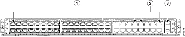
1 |
GE copper port |
3 |
1G/10G SFP/SFP+ port |
|
2 |
2.5G mGiG copper port |
|
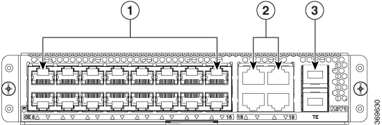
1 |
GE copper port |
3 |
1G/10G SFP/SFP+ port |
|
2 |
2.5G mGiG copper port |
Use the following procedure to install the Cisco SM-X-16G4M2X or SM-X-40G8M2X service module on your router:
Procedure
| Step 1 |
Read the Safety Warnings before you perform any module replacement. |
||
| Step 2 |
For Cisco SM-X-16G4M2X module, remove the blank faceplate installed over the router's slot you intend to use. |
||
| Step 3 |
For SM-X-40G8M2X module, remove both the blank faceplates and the divider installed over the router's slot you intend to use.
|
||
| Step 4 |
With the SM-X-16G4M2X service module, push the module into place until you feel the edge connector seat securely into the connector on the router backplane. The module faceplate should contact the chassis rear panel. OR |
||
| Step 5 |
For SM-X-40G8M2X service module, keep the latches in open position before inserting the module. The latches assist to fully insert the module before securing the screws. |
||
| Step 6 |
Using a number 1 Phillips or flat-blade screwdriver, tighten the captive mounting screws on the module faceplate. For more information on installing the single-wide and double-wide service module, see the Cisco 4000 Series Installation Guide. |
Verifying Cisco SM-X-16G4M2X or SM-X-40G8M2X Service Module Installation
Use the show platform command to verify that the Cisco SM-X-16G4M2X or the SM-X-40G8M2X service module is installed. The following example shows that the Cisco SM-X-16G4M2X service module is installed and recognized by the system.
Device#show platform
Chassis type: ISR4331/K9

Slot      Type                State                 Insert time (ago)
--------- ------------------- --------------------- -----------------
0         ISR4331/K9          ok                    2d01h
 0/0      ISR4331-3x1GE       ok                    2d01h
 0/1      NIM-4BRI-S/T        ok                    2d01h
 0/2      NIM-4BRI-S/T        ok                    2d01h
1         ISR4331/K9          ok                    2d01h
 1/0      SM-X-16G4M2X        ok                    2d01h
R0        ISR4331/K9          ok, active            2d01h
F0        ISR4331/K9          ok, active            2d01h
P0        PWR-4330-POE-AC     ok                    2d01h
P2        ACS-4330-FANASSY    ok                    2d01h

Slot      CPLD Version        Firmware Version
--------- ------------------- ---------------------------------------
0         14101324            16.12(1r)
1         14101324            16.12(1r)
R0        14101324            16.12(1r)
F0        14101324            16.12(1r)
Removing Cisco SM-X-16G4M2X or SM-X-40G8M2X Service Module from the Chassis
Use the following procedure to remove the SM-X-16G4M2X or SM-X-40G8M2X service module from your router:
Procedure
| Step 1 |
Read the Safety Warnings before you perform any module replacement. |
| Step 2 |
Locate the Cisco SM-X-16G4M2X or SM-X-40G8M2X service module to be removed. |
| Step 3 |
Using a number 1 Phillips or flat-blade screwdriver, unscrew the captive mounting screws on the module faceplate. |
| Step 4 |
Pull the Cisco SM-X-16G4M2X module out of the chassis. |
| Step 5 |
For Cisco SM-X-40G8M2X module, keep the latches in open position and pull the Cisco SM-X-40G8M2X module out of the chassis. |
| Step 6 |
Place the service module in an antistatic bag to protect it from electrostatic discharge (ESD) damage. |
Installing SFP and SFP+ Modules
Before you begin
See the Cisco 4000 Series ISRs data sheet on Cisco.com for a list of supported SFP and SFP+ modules. Use only supported SFP/SFP+ modules on the router.
 Warning |
Class 1 laser product. Statement 1008 |
-
Do not remove the dust plugs from the SFP and SFP+ modules or the rubber caps from the fiber-optic cable until you are ready to connect the cable. The plugs and caps protect the module ports and cables from contamination and ambient light.
-
Removing and installing an SFP and SFP+ module can shorten its useful life. Do not remove and insert any SFP/SFP+ module more often than is necessary.
-
To prevent ESD damage, follow your normal board and component handling procedures when connecting cables to the switch and other devices.
-
When you insert several SFP and SFP+ modules in multiple ports, wait for 5 seconds between inserting each SFP/SFP+. This will prevent the ports from going into error disabled mode. Similarly, when you remove an SFP and SFP+ from a port, wait for 5 seconds before reinserting it.
Procedure
| Step 1 |
Attach an ESD-preventive wrist strap to your wrist and to an earth ground surface. |
| Step 2 |
Find the send (TX) and receive (RX) markings that identify the top of the SFP/SFP+ module. On some SFP/SFP+ modules, the send and receive (TX and RX) markings might be shown by arrows that show the direction of the
connection.
|
| Step 3 |
If the SFP/SFP+ module has a bale-clasp latch, move it to the open, unlocked position. |
| Step 4 |
Align the module in front of the slot opening, and push until you feel the connector snap into place. |
| Step 5 |
If the module has a bale-clasp latch, close it to lock the SFP/SFP+ module in place. |
| Step 6 |
Remove the SFP and SFP+ dust plugs and save. |
| Step 7 |
Connect the SFP and SFP+ cables. |
LED Indicators
You can check the status of the SM-X-16G4M2X or SM-X-40G8M2X service module by referring to LED indicators. The following table summarizes the LED indicators that are located on the bezel of the service module.
|
LED |
Color |
Status |
Control Source |
|---|---|---|---|
|
Power |
Green+Amber |
System Power Status Off: Powered off Green Steady On: Powered on and operational Amber Steady on Or Blink: System at booting stage or power failure |
Host through I2C |
|
GiG and mGiG |
Green+Amber |
GiG and mGiG Status Off: Link down Blinking Green : Link up, and active Solid Green : Link up, no activity Solid Amber : POE Rejected |
PHY |
|
SFP/SFP+ LEDs |
Green+Amber |
SFP/SFP+ Status Off: No SFP detected or inserted Blinking Green : SFP is powered up and enabled, active Solid Green : SFP is powered up and enabled, no activity Solid Amber : Gets led off if SFP is detected, but not enabled due to error(l non-supported SFP is inserted) |
I/O |
Connecting to Cisco SM-X-16G4M2X or SM-X-40G8M2X Service Module
Before you can access the module, you must connect to the host router through the router console or through Telnet. After you are connected to the router, you must configure an IP address on the Gigabit Ethernet interface connected to your module. Open a session to your module using the hw-module session command in privileged EXEC mode on the router.
To establish a connection to the module, connect to the router console using Telnet or Secure Shell (SSH) and open a session to the switch using the hw-module session slot/subslot command in privileged EXEC mode on the router.
Router# hw-module session slot/card
Router# hw-module session 0/1 endpoint 0

Establishing session connect to subslot 0/1
Note |
Connecting a GE port to the network requires a Category 5 cable with RJ-45 male connectors, not provided with the module. Category 5 cables are widely available. |
DANGER |
To comply with the standard for electromagnetic compatibility and safety, connect the Cisco SM-X-16G4M2X or SM-X-40G8M2X only to intra-building or unexposed wiring or cable. The intra-building port(s) of the equipment or subassembly must not be metallically connected to interfaces that connect to the OSP or its wiring. These interfaces are designed for use as intra-building interfaces only (Type 2 or Type 4 ports as described in GR-1089-CORE, Issue 4) and require isolation from the exposed OSP cabling. The addition of Primary Protectors is not sufficient protection in order to connect these interfaces metallically to OSP wiring. The intra-building cable must be shielded and the shield must be grounded at both ends. |
Related Documents
|
Related Topic |
Document Title |
|---|---|
|
Configuration guide for the Cisco SM-X-16G4M2X Service Module |
Configuring the Cisco SM-X-16G4M2X EtherSwitch Service Module |
|
Hardware installation instructions for service modules |
Hardware Installation Guide for the Cisco 4000 Series Integrated Services Router |
|
General information about configuration and the command reference. |
Software Configuration Guide for the Cisco 4000 Seris Integrated Services Router |
|
Regulatory compliance information for the Cisco 4000 Series ISR. |
Regulatory Compliance and Safety Information for the Cisco 4000 Series Integrated Services Router |
 Feedback