Connecting the Cisco 6-port GE SFP Service Modules and Cisco 4-port GE SFP and 1-port 10 GE SFP Service Modules to the Network
Available Languages
Table of Contents
Software Requirements for the Cisco SM-X-6X1G and Cisco SM-X-4X1G-1X10G
Removing the Cisco SM-X-6X1G and Cisco SM-X-4X1G-1X10G from the Router
Installing the Cisco SM-X-6X1G and Cisco SM-X-4X1G-1X10G in the Router
Verifying Cisco SM-X-6X1G and Cisco SM-X-4X1G-1X10G Installation in a Cisco Router
Connecting the Cisco 6-port GE SFP Service Modules and the Cisco 4-port GE SFP and 1-port 10 GE SFP Service Modules to the Network
This document describes how to install a Cisco 6-port GE SFP Service Module and Cisco 4-port GE SFP and 1-port 10 GE SFP Service Module on the Cisco ISR 4400 Series Routers and how to connect the service module to your network.
Contents
This guide contains the following sections:
- About the Cisco 6-port GE SFP Service Module and Cisco 4-port GE SFP and 1-port 10 GE SFP Service Module
- Service Module GE Ports
- Service Module LEDs
- Conventions
- Safety Warnings
- Installing and Removing the Cisco SM-X-6X1G and Cisco SM-X-4X1G-1X10G on Cisco ISR 4400 Series Routers
- Additional References
About the Cisco 6-port GE SFP Service Module and Cisco 4-port GE SFP and 1-port 10 GE SFP Service Module
The Cisco SM-X-6X1G and Cisco SM-X-4X1G-1X10G are multi GE service modules for the Cisco ISR 4400 Series routers.
The SM-X-4X1G-1X10G provides one 10GE and four 1GE ports. You can configure this service module to use either a single 10GE port or four 1GE ports.
The SM-X-6X1G provides six 1GE routing ports.
The service module provides the following external interfaces:
- 10/100/1000 Mbps RJ45 interface with Speed and Link LEDs
- SFP interface with Speed and EN LEDs
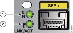
- SFP+ interface with LNK/ACT and EN LEDs
Figure 1 shows the faceplate of the Cisco SM-X-6X1G service module.
Figure 1 Cisco SM-X-6X1G Service Module
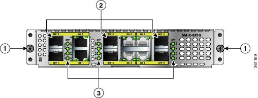
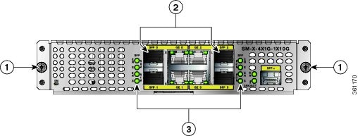
Figure 2 shows the faceplate of the Cisco SM-X-4X1G-1X10G service module.
Figure 2 Faceplate of the Cisco SM-X-4X1G-1X10G Service Module
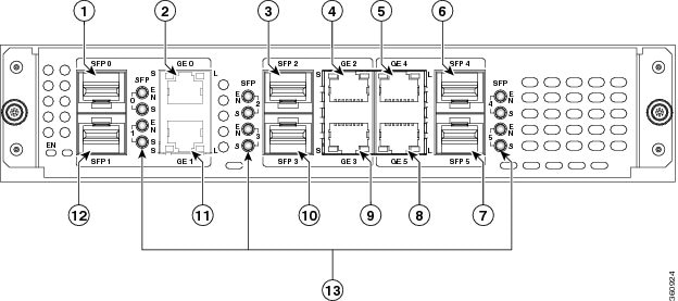
Service Module GE Ports
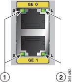
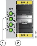
Figure 3 and Figure 4 show the various ports on the Cisco SM-X-6X1G and Cisco SM-X-4X1G-1X10G:
Figure 3 Front Ports on the SM-X-4X1G-1X10G
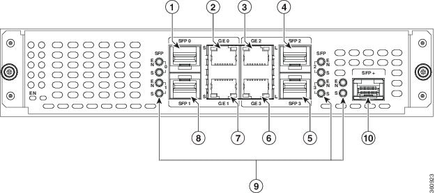
Figure 4 Front Ports on the SM-X-6X1G
Service Module LEDs
The Cisco SM-X-6X1G and Cisco SM-X-4X1G-1X10G enhanced service module includes several indicator LEDs. The following figures show the port LEDs on the service modules. Table 1 describes the LEDs.
Conventions

Note
Means reader take note. Notes contain helpful suggestions or references to additional information and material.

Caution

Tip

Warning
This warning symbol means danger. You are in a situation that could cause bodily injury. Before you work on any equipment, be aware of the hazards involved with electrical circuitry and be familiar with standard practices for preventing accidents. Use the statement number provided at the end of each warning statement to locate its translation in the translated safety warnings that accompanied this device. Statement 1071
SAVE THESE INSTRUCTIONS
Safety Warnings
Warning
Warning
Warning
Warning
Warning
Warning
Warning
Warning
Warning
Warning
Warning
Warning
Warning
Warning
Warning
Warning
Warning
Warning
T3, E3 Statement 1044
Installing and Removing the Cisco SM-X-6X1G and Cisco SM-X-4X1G-1X10G on Cisco ISR 4400 Series Routers
This section describes the following tasks for the Cisco SM-X-6X1G and Cisco SM-X-4X1G-1X10G enhanced service module:
- Software Requirements for the Cisco SM-X-6X1G and Cisco SM-X-4X1G-1X10G
- Removing the Cisco SM-X-6X1G and Cisco SM-X-4X1G-1X10G from the Router
- Installing the Cisco SM-X-6X1G and Cisco SM-X-4X1G-1X10G in the Router
- Verifying Cisco SM-X-6X1G and Cisco SM-X-4X1G-1X10G Installation in a Cisco Router
Caution
Caution
Caution
Software Requirements for the Cisco SM-X-6X1G and Cisco SM-X-4X1G-1X10G
Cisco IOS XE Release 3.11S or later release is required to operate the SM-X-6X1G and Cisco IOS XE Release 3.13S to operate the SM-X-4X1G-1X10G enhanced service module on a Cisco router. However, Cisco IOS XE Release 3.13.1 or later is the recommended version for both the SMs.
To determine the version of Cisco IOS software that is running on your router, log in to the router and enter the show version command:
Removing the Cisco SM-X-6X1G and Cisco SM-X-4X1G-1X10G from the Router
Use the following procedure to remove the Cisco SM-X-6X1G and Cisco SM-X-4X1G-1X10G from a Cisco router:
Step 1
Step 2
Step 3
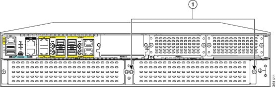
Figure 8 Removing a module from the Router (Model Shown: Cisco ISR 4451-X)
Step 4
Step 5
Installing the Cisco SM-X-6X1G and Cisco SM-X-4X1G-1X10G in the Router
Use the following procedure to install the Cisco SM-X-6X1G and Cisco SM-X-4X1G-1X10G on a Cisco router:
Step 1
Step 2
Step 3
Step 4
Verifying Cisco SM-X-6X1G and Cisco SM-X-4X1G-1X10G Installation in a Cisco Router
Use the show diag command to verify that the Cisco SM-X-6X1G and Cisco SM-X-4X1G-1X10G has been installed correctly.
In the following example, the SM-X-6X1G service module is recognized by the system.
In the following example, the SM-X-4X1G-1X10G service module is recognized by the system:
Additional References
Related Documents
Configuring Cisco SM-X-6X1G and Cisco SM-X-4X1G-1X10G software
Software Configuration Guide for the Cisco 6-port GE SFP Service Module and Cisco 4-port GE SFP and 1-port 10 GE SFP Service Module
Cisco Service Module Regulatory Compliance and Safety Information
Technical Assistance
Cisco and the Cisco logo are trademarks or registered trademarks of Cisco and/or its affiliates in the U.S. and other countries. To view a list of Cisco trademarks, go to this URL: www.cisco.com/go/trademarks. Third-party trademarks mentioned are the property of their respective owners. The use of the word partner does not imply a partnership relationship between Cisco and any other company. (1110R)
Any Internet Protocol (IP) addresses and phone numbers used in this document are not intended to be actual addresses and phone numbers. Any examples, command display output, network topology diagrams, and other figures included in the document are shown for illustrative purposes only. Any use of actual IP addresses or phone numbers in illustrative content is unintentional and coincidental.
© 2014 Cisco Systems, Inc. All rights reserved.
 Feedback
Contact Cisco
- Open a Support Case

- (Requires a Cisco Service Contract)