Feedback Feedback
|
Table Of Contents
Software Configuration Guide for the Cisco 6-port GE SFP Service Module
Requirements for the Cisco SM-X-6X1G
Configuring the Cisco SM-X-6X1G
Specifying the Interface Address on a SM
Modifying the MAC Address on an Interface
Configuring the Hot Standby Router Protocol
Modifying the Interface MTU Size
Interface MTU Configuration Guidelines
Interface MTU Configuration Task
Ingress QoS Classification for IPv4 and IPv6
Configuring the Encapsulation Type
Configuring Autonegotiation on an Interface
Configuring a Subinterface on a VLAN
Addition of Warning Message when Enabling VLAN Scale Configuration
Verifying Subinterface Configuration on a VLAN
Shutting Down and Restarting an Interface on a SM
Configuring Ethernet Flow Control
Verifying the Interface Configuration
Verifying Per-Port Interface Status
Verifying Configuration and Classification Counters on an Interface
Using show Commands to Check SFP Module Status
Software Configuration Guide for the Cisco 6-port GE SFP Service Module
Last Updated: December 5, 2013OL-30170-01Contents
•
Requirements for the Cisco SM-X-6X1G
•
•
•
About the SM-X-6X1G Modules
The Cisco 6-port GE SFP Service Modules are software-configurable high-speed connectivity routing port service modules for the Cisco 4451-X Integrated Services Router (Cisco ISR 4451-X). These service modules provide increased density of ethernet interfaces on the Cisco ISR 4451-X and offer the following SKU:
•
The SM-X-6X1G is a multi gigabit ethernet service module for the Cisco 4451-X Integrated Services Routers (Cisco ISR 4451-X).
The SM-X-6X1G provides six 1 GB ethernet routing ports.
The SM-X-6X1G include the following features:
•
•
•
•
•
•
•
•
•
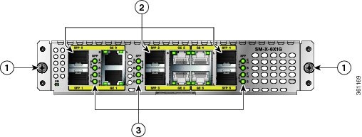
Figure 1-1 shows the faceplate of the Cisco SM-X-6X1G service module.
Figure 1-1 Cisco SM-X-6X1G Service Module
Service Module LEDs
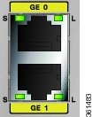
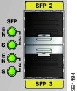
The SM-X-6X1G enhanced service module includes several indicator LEDs. Figure 1-3 and Figure 1-3 show the LEDs available on the service module. Table 1 describes the LEDs on the SM-X-6X1G.
Figure 1-2
SM-X-6X1G LEDs
Figure 1-3
SM-X-6X1G LEDs
Requirements for the Cisco SM-X-6X1G
Cisco IOS/IOS XE Requirements
Table 2 describes Cisco IOS/IOS XE requirements for operating the Cisco SM-X-6X1G.
Table 2 Cisco IOS/IOS XE Requirements
Cisco ISR 4451-X routers
Cisco IOS XE release 3.11 or later
Memory Requirements
Table 3 describes the minimum platform memory recommended for operating the Cisco SM-X-6X1G.
Table 3 Cisco SM-X-6X1G Minimum Memory Requirements
Cisco ISR 4451-X routers
8 Mb
Finding Support Information for Platforms and Cisco IOS Software Images
Your software release may not support all the features documented in this module. For the latest feature information and caveats, see the release notes for your platform and software release. Use Cisco Feature Navigator to find information about platform support and Cisco software image support. To access Cisco Feature Navigator, go to http://www.cisco.com/go/cfn. An account on Cisco.com is not required.
Restrictions
The following are the restrictions with the use of the Cisco SM-X-6X1G service modules:
•
•
Configuring the Cisco SM-X-6X1G
This section describes how to configure the Cisco SM-X-6X1G and includes information about verifying the configuration.
This section includes the following topics:
•
•
•
•
•
•
•
•
•
•
Required Configuration Tasks
This section lists the required configuration steps to configure the Cisco SM-X-6X1G. Some of the required configuration commands implement default values that might be appropriate for your network. If the default value is correct for your network, then you do not need to configure the command. These commands are indicated by "(As Required)" in the Purpose column.
To configure the Cisco SM-X-6X1G, complete the following steps:
Step 1
Router# configure terminal
Enters global configuration mode.
Step 2
Router(config)# interface GigabitEthernet slot/subslot/port[.subinterface-number]
or
Router(config)# interface TenGigabitEthernet slot/subslot/port[.subinterface-number]
Specifies the Gigabit Ethernet, or Ten Gigabit Ethernet interface to configure, where:
•
•
Step 3
Router(config-if)# ip address [ip-address mask {secondary} | dhcp {client-id interface-name}{hostname host-name}]
Sets a primary or secondary IP address for an interface that is using IPv4, where:
•
•
•
•
•
•
Step 4
Router(config-if)# mtu bytes
(As Required) Specifies the maximum packet size for an interface, where:
•
The default is 1500 bytes; the range is 1500 to 9216.
Step 5
Router(config-if)# standby [group-number] ip [ip-address [secondary]]
(Required for HSRP Configuration Only) Creates (or enables) the HSRP group using its number and virtual IP address, where:
•
•
•
This command enables HSRP but does not configure it further. For additional information on configuring HSRP, refer to the HSRP section of the Cisco IP Configuration Guide publication that corresponds to your Cisco IOS software release.
Step 6
Router(config-if)# no shutdown
Enables the interface.
Specifying the Interface Address on a SM
SM interface ports begin numbering with "0" from left to right. Single-port SMs use only the port number 0. To configure or monitor SM interfaces, you need to specify the physical location of the SM, and interface in the CLI. The interface address format is slot/subslot/port, where:
•
•
•
The following example shows how to specify the first interface (0) on a SM installed in the first subslot of a SIP (0) installed in chassis slot 1:
Router(config)# interface GigabitEthernet 1/0/0interface GigabitEthernet1/0/0no ip addressshutdownnegotiation autono cdp enableModifying the MAC Address on an Interface
The Cisco SM-X-6X1G use a default MAC address for each port that is derived from the base address that is stored in the electrically erasable programmable read-only memory (EEPROM) on the backplane of the Cisco ISR 4451-X.
To modify the default MAC address of an interface to some user-defined address, use the following command in interface configuration mode:
To return to the default MAC address on the interface, use the no form of the command.
Verifying a MAC Address
To verify the MAC address of an interface, use the show interfaces gigabitethernet privileged EXEC command and observe the value shown in the "address is" field.
The following example shows that the MAC address is a44c.119e.0884 (bia a44c.119e.0884) for interface 2 on the SM installed in subslot 0 of the SIP installed in slot 0 of the Cisco ISR 4451-X:
router#show interface gigabitEthernet 1/0/0GigabitEthernet1/0/0 is up, line protocol is upHardware is SM-X-6X1G, address is a44c.119e.0884 (bia a44c.119e.0884)Internet address is 3.0.0.1/24MTU 1500 bytes, BW 100000 Kbit/sec, DLY 100 usec,reliability 255/255, txload 1/255, rxload 1/255Encapsulation ARPA, loopback not setKeepalive not supportedHalf Duplex, 100Mbps, link type is force-up, media type is RJ45output flow-control is on, input flow-control is onARP type: ARPA, ARP Timeout 04:00:00Last input never, output 00:00:55, output hang neverLast clearing of "show interface" counters neverInput queue: 0/375/0/0 (size/max/drops/flushes); Total output drops: 440722919Queueing strategy: fifoOutput queue: 0/40 (size/max)5 minute input rate 0 bits/sec, 0 packets/sec5 minute output rate 0 bits/sec, 0 packets/sec(Additional output removed for readability)Configuring the Hot Standby Router Protocol
The Hot Standby Router Protocol (HSRP) provides high network availability because it routes IP traffic from hosts without relying on the availability of any single router. HSRP is used in a group of routers for selecting an active router and a standby router. (An active router is the router of choice for routing packets; a standby router is a router that takes over the routing duties when an active router fails, or when preset conditions are met).
HSRP is enabled on an interface by entering the standby [group-number] ip [ip-address [secondary]] command. The standby command is also used to configure various HSRP elements. This document does not discuss more complex HSRP configurations. For additional information on configuring HSRP, refer to the HSRP section of the Cisco IP Configuration Guide publication that corresponds to your Cisco IOS XE software release. In the following HSRP configuration, standby group 2 on Gigabit Ethernet port 2/1/0 is configured at a priority of 110 and is also configured to have a preemptive delay should a switchover to this port occur:
Router(config)#interface GigabitEthernet 2/0/xRouter(config-if)#standby 2 ip 120.12.1.200Router(config-if)#standby 2 priority 110Router(config-if)#standby 2 preemptVerifying HSRP
To verify the HSRP information, use the show standby command in EXEC mode:
Router# show standbyEthernet0 - Group 0Local state is Active, priority 100, may preemptHellotime 3 holdtime 10Next hello sent in 0:00:00Hot standby IP address is 198.92.72.29 configuredActive router is localStandby router is 198.92.72.21 expires in 0:00:07Standby virtual mac address is 0000.0c07.ac00Tracking interface states for 2 interfaces, 2 up:UpSerial0UpSerial1Modifying the Interface MTU Size
The Cisco IOS software supports three different types of configurable maximum transmission unit (MTU) options at different levels of the protocol stack:
•
•
•
Different encapsulation methods and the number of MPLS MTU labels add additional overhead to a packet. For example, Subnetwork Access Protocol (SNAP) encapsulation adds an 8-byte header, dot1q encapsulation adds a 2-byte header, and each MPLS label adds a 4-byte header (n labels x 4 bytes).
For Cisco SM-X-6X1G on the Cisco ISR 4451-X, the default MTU size is 1500 bytes. The maximum configurable MTU is 9216 bytes. The SM automatically adds an additional 22 bytes to the configured MTU size to accommodate some of the additional overhead.
Note
Interface MTU Configuration Guidelines
When configuring the interface MTU size on a Gigabit Ethernet SM on a Cisco ISR 4451-X, consider the following guidelines:
•
–
–
–
•
•
Interface MTU Configuration Task
To modify the MTU size on an interface, use the following command in interface configuration mode:
To return to the default MTU size, use the no form of the command.
Verifying the MTU Size
To verify the MTU size for an interface, use the show interfaces gigabitethernet privileged EXEC command and observe the value shown in the "MTU" field.
The following example shows an MTU size of 1500 bytes for interface port 0 on the Gigabit Ethernet SM installed in the top subslot (0) of the SIP that is located in slot 2 of the Cisco ISR 4451-X:
router#show interface gigabitEthernet 2/0/2GigabitEthernet2/0/2 is up, line protocol is upHardware is SM-X-6X1G, address is a44c.119e.0884 (bia a44c.119e.0884)Internet address is 3.0.0.1/24MTU 1500 bytes, BW 100000 Kbit/sec, DLY 100 usec,reliability 255/255, txload 1/255, rxload 1/255Encapsulation ARPA, loopback not setKeepalive not supportedHalf Duplex, 100Mbps, link type is force-up, media type is RJ45output flow-control is on, input flow-control is onARP type: ARPA, ARP Timeout 04:00:00Last input never, output 00:00:55, output hang neverLast clearing of "show interface" counters neverInput queue: 0/375/0/0 (size/max/drops/flushes); Total output drops: 440722919Queueing strategy: fifoOutput queue: 0/40 (size/max)5 minute input rate 0 bits/sec, 0 packets/sec5 minute output rate 0 bits/sec, 0 packets/sec557663005 packets input, 33459780300 bytes, 0 no bufferReceived 0 broadcasts (0 IP multicasts)0 runts, 0 giants, 0 throttles0 input errors, 0 CRC, 0 frame, 0 overrun, 0 ignored0 watchdog, 0 multicast, 0 pause input451428325 packets output, 27800558158 bytes, 0 underruns0 output errors, 0 collisions, 7 interface resets0 unknown protocol drops0 babbles, 0 late collision, 0 deferred0 lost carrier, 0 no carrier, 0 pause output0 output buffer failures, 0 output buffers swapped outIngress QoS Classification for IPv4 and IPv6
The SM-X-6X1G module support two priority queues per port on ingress. The high-priority queue is always processed before the low-priority queue.
Restrictions
•
•
•
•
Note
Use the following commands in interface configuration mode to configure ingress QoS classification for IPv4/IPv6:
Configuring the Encapsulation Type
By default, the interfaces on the Cisco SM-X-6X1G support Advanced Research Projects Agency (ARPA) encapsulation. They do not support configuration of service access point or SNAP encapsulation for transmission of frames.
The only other encapsulation supported by the SM interfaces is IEEE 802.1Q encapsulation for virtual LANs (VLANs).
Configuring Autonegotiation on an Interface
The Gigabit Ethernet interfaces use a connection-setup algorithm called autonegotiation. Autonegotiation allows the local and remote devices to configure compatible settings for communication over the link. Using autonegotiation, each device advertises its transmission capabilities and then agrees upon the settings to be used for the link.
For the Gigabit Ethernet interfaces on the Cisco ISR 4451-X, flow control is autonegotiated when autonegotiation is enabled. Autonegotiation is enabled by default.
The following guidelines should be followed regarding autonegotiation:
•
•
•
Enabling Autonegotiation
To re-enable autonegotiation on a Gigabit Ethernet interface, use the following command in interface configuration mode:
Router(config-if)# negotiation auto
Enables autonegotiation on a Gigabit Ethernet SM interface on the Cisco ISR 4451-X routers. Advertisement of flow control occurs.
Disabling Autonegotiation
Autonegotiation is automatically enabled and can be disabled on the Gigabit Ethernet interfaces on the Cisco ISR 4451-X routers. During autonegotiation, advertisement for flow control, speed, and duplex occurs, depending on the media (fiber or copper) in use. If the interface is connected to a link that has autonegotiation disabled, autonegotiation should either be re-enabled on the other end of the link or disabled on the Gigabit Ethernet SM, if possible. Both ends of the link will not come up properly if only one end of the link has disabled autonegotiation.
Speed and duplex configurations can be advertised using autonegotiation. However, the only values that are negotiated are:
•
From a user's perspective, these settings are not really negotiated, but rather are enabled using autonegotiation. The SFPs for Cisco SM-X-6X1G support 1000Base-X, and the IEEE 1000Base-X standard for fiber does not support negotiation of link speed.
To disable autonegotiation, use the following command in interface configuration mode:
Router(config-if)# no negotiation auto
Disables autonegotiation on Gigabit Ethernet SM interfaces on the Cisco ISR 4451-X routers. No advertisement of flow control occurs.
Configuring Speed and Duplex
Note
If the media-type is SFP, after disabling "negotiation auto", some SFPs allow you to configure duplex mode (half or full) but the speed cannot be manually changed.
For SFP+, speed- and duplex-related CLIs are not available and cannot be manually configured..
To configure the speed for a Gigabit Ethernet interface, use the speed command in interface configuration mode. To return to the default setting, use the no form of this command:
Router(config-if)# speed {10 | 100 | 1000}
Configures the interface to transmit at 10 Mbps, 100 Mbps, or 1000 Mbps. (The 1000 keyword is only valid for Gigabit Ethernet.)
To configure duplex operation on an interface, use the duplex command in interface configuration mode. Use the no form of this command to return to the default value.
Configuring the Media Type
The Gigabit Ethernet SMs support two media types: RJ-45 and SFP. Use the media-type configuration command to select either the RJ-45 or SFP for a given port.
Router(config-if)# media-type { rj45 | sfp}
Specifies the physical connection on an interface.
Configuring a Subinterface on a VLAN
You can configure subinterfaces on the Gigabit Ethernet SM interfaces on a VLAN using IEEE 802.1Q encapsulation. Cisco Discovery Protocol (CDP) is disabled by default on the Gigabit Ethernet SM interfaces and subinterfaces on the Cisco ISR 4451-X routers.
To configure a SM interface on a VLAN, use the following commands beginning in global configuration mode:
Step 1
Router(config)# interface gigabitethernet slot/subslot/port.subinterface-number
or
Router(config)# interface tengigabitethernet slot/subslot/port.subinterface-number
Specifies the Gigabit Ethernet interface to configure, where:
•
•
Step 2
Router(config-subif)# encapsulation dot1q vlan-id
Defines the encapsulation format as IEEE 802.1Q ("dot1q"), where vlan-id is the number of the VLAN (1-4094).
Step 3
Router(config-if)# ip address ip-address mask [secondary]
Sets a primary or secondary IP address for an interface, where:
•
•
•
VLAN Classification
Addition of Warning Message when Enabling VLAN Scale Configuration
To specify VLAN classification, use the following commands in physical router configuration mode:
Verifying Subinterface Configuration on a VLAN
To verify the configuration of a subinterface and its status on the VLAN, use the show vlans privileged EXEC command.
The following example shows the status of subinterface number 1 on port 0 on the SM in VLAN number 200:
Router# show vlansVLAN ID:200 (IEEE 802.1Q Encapsulation)Protocols Configured: Received: Transmitted:IP 0 2VLAN trunk interfaces for VLAN ID 200:GigabitEthernet1/0/0.1 (200)IP:12.200.21.21Total 0 packets, 0 bytes inputTotal 2 packets, 120 bytes outputSaving the Configuration
To save your running configuration to nonvolatile random-access memory (NVRAM), use the following command in privileged EXEC configuration mode:
For information about managing your system image and configuration files, refer to the Cisco IOS Configuration Fundamentals Configuration Guide and Cisco IOS Configuration Fundamentals Command Reference publications that correspond to your Cisco IOS software release.
Shutting Down and Restarting an Interface on a SM
You can shut down and restart any of the interface ports on a SM independently of each other. Shutting down an interface stops traffic and enters the interface into an "administratively down" state.
There are no restrictions for online insertion and removal (OIR) on Cisco SM-X-6X1G. Cisco SM-X-6X1G can be removed from a SIP at any time. SIPs populated with any type of SMs can be removed from the router at any time.
If you are preparing for an OIR of a SM, it is not necessary to independently shut down each of the interfaces prior to deactivation of the SM. The hw-module subslot stop command automatically stops traffic on the interfaces and deactivates them along with the SM in preparation for OIR.
In similar fashion, you do not need to independently restart any interfaces on a SM after OIR of a SM or SIP.
To shut down an interface on a SM, use the following command in interface configuration mode:
To restart an interface on a SM, use the following command in interface configuration mode:
Configuring Ethernet Flow Control
To configure ethernet flow control per queue per port, use the following commands in the interface configuration mode:
Verifying the Interface Configuration
Besides using the show running-configuration command to display your Cisco ISR 4451-X configuration settings, you can use the show interfaces gigabitethernet command to get detailed information on a per-port basis for your Cisco SM-X-6X1G.
Verifying Per-Port Interface Status
To find detailed interface information on a per-port basis for the Cisco SM-X-6X1G, use the show interfaces gigabitethernet command.
The following example provides sample output for interface port 0 on the SM located in the top subslot (0) of the SIP that is installed in slot 2 of the Cisco ISR 4451-X:
router#show interface gigabitEthernet 2/0/0GigabitEthernet2/0/0 is up, line protocol is upHardware is SM-X-6X1G, address is a44c.119e.0884 (bia a44c.119e.0884)Internet address is 3.0.0.1/24MTU 1500 bytes, BW 100000 Kbit/sec, DLY 100 usec,reliability 255/255, txload 1/255, rxload 1/255Encapsulation ARPA, loopback not setKeepalive not supportedHalf Duplex, 100Mbps, link type is force-up, media type is RJ45output flow-control is on, input flow-control is onARP type: ARPA, ARP Timeout 04:00:00Last input never, output 00:00:55, output hang neverLast clearing of "show interface" counters neverInput queue: 0/375/0/0 (size/max/drops/flushes); Total output drops: 440722919Queueing strategy: fifoOutput queue: 0/40 (size/max)5 minute input rate 0 bits/sec, 0 packets/sec5 minute output rate 0 bits/sec, 0 packets/sec557663005 packets input, 33459780300 bytes, 0 no bufferReceived 0 broadcasts (0 IP multicasts)0 runts, 0 giants, 0 throttles0 input errors, 0 CRC, 0 frame, 0 overrun, 0 ignored0 watchdog, 0 multicast, 0 pause input451428325 packets output, 27800558158 bytes, 0 underruns0 output errors, 0 collisions, 7 interface resets0 unknown protocol drops0 babbles, 0 late collision, 0 deferred0 lost carrier, 0 no carrier, 0 pause output0 output buffer failures, 0 output buffers swapped outVerifying Configuration and Classification Counters on an Interface
Use the following show commands to verify the configuration and classification counters on an interface:
Using show Commands to Check SFP Module Status
You can use various show commands to view information specific to SFP and SFP+ optical transceiver modules.
To check or verify the status of an SFP Module or SFP+ Module, use the following show commands:
•
•
•
•
•
Following are sample output of several show commands for SFP Modules and SFP+ Modules.
The following show hw-module subslot command sample output is for SFP-GE-S:
Router# show hw-module subslot 2/0 transceiver 0 idpromIDPROM for transceiver GigabitEthernet2/0/0: Description = SFP optics (type 3) Transceiver Type: = GE SX (19) Product Identifier (PID) = FTRJ8519P1BNL-C6 Vendor Revision = A Serial Number (SN) = FNS1037R8DH Vendor Name = CISCO-FINISAR Vendor OUI (IEEE company ID) = 00.90.65 (36965) CLEI code = IPUIALJRAA Cisco part number = 10-2143-01 Device State = Enabled. Date code (yy/mm/dd) = 06/09/14 Connector type = LC. Encoding = 8B10B NRZ Nominal bitrate = GE (1300 Mbits/s) Minimum bit rate as % of nominal bit rate = not specified Maximum bit rate as % of nominal bit rate = not specifiedThe following show hw-module subslot command sample output is for SFP-GE-SX:
Router# show hw-module subslot 2/0 transceiver 0 idprom dump
IDPROM for transceiver GigabitEthernet2/0/0:
Description = SFP optics (type 3)
Transceiver Type: = GE SX (19)
Product Identifier (PID) = FTRJ8519P1BNL-C6
Vendor Revision = A
Serial Number (SN) = FNS1037R8DH
Vendor Name = CISCO-FINISAR
Vendor OUI (IEEE company ID) = 00.90.65 (36965)
CLEI code = IPUIALJRAA
Cisco part number = 10-2143-01
Device State = Enabled.
SFP IDPROM Page 0xA0: 000: 03 04 07 00 00 00 01 00 00 00 010: 00 01 0D 00 00 00 37 1B 00 00 020: 43 49 53 43 4F 2D 46 49 4E 49 030: 53 41 52 20 20 20 00 00 90 65 040: 46 54 52 4A 38 35 31 39 50 31 050: 42 4E 4C 2D 43 36 41 20 20 20 060: 03 52 00 74 00 1A 00 00 46 4E 070: 53 31 30 33 37 52 38 44 48 20 080: 20 20 20 20 30 36 30 39 31 34 090: 20 20 58 80 01SFP IDPROM Page 0xA2: 000: 6D 00 E3 00 67 00 F3 00 98 58 010: 69 78 90 88 71 48 1D 4C 01 F4 020: 17 70 03 E8 25 19 02 F5 25 19 030: 04 A9 E3 EE 01 DF 8F C5 02 EC 040: 00 00 00 00 00 00 00 00 00 00 050: 00 00 00 00 00 00 00 00 00 00 060: 00 00 00 00 00 00 00 00 3E 5D 070: 01 79 C0 5B AC 86 01 00 00 00 080: 00 AA FF FD 01 00 00 00 01 00 090: 00 00 00 00 00 3A 1B 70 80 D8 100: 00 62 00 28 00 22 00 00 00 00 110: 82 F8 05 40 00 00 05 40 00 00 120: 00 00 00 00 00 00 00 01 49 50 130: 55 49 41 4C 4A 52 41 41 31 30 140: 2D 32 31 34 33 2D 30 31 56 30 150: 31 20 89 FB 55 00 00 00 00 78 160: 00 00 00 00 00 00 00 00 00 00 170: 00 00 00 00 00 00 00 00 00 00 180: 00 00 00 00 00 00 00 00 00 00 190: AA AA 53 46 50 2D 47 45 2D 53 200: 20 20 20 20 20 20 20 20 20 20 210: 20 20 00 00 00 00 00 00 00 00 220: 00 00 00 A2 00 00 00 00 00 00 230: 00 00 00 00 00 00 00 00 00 00 240: 00 00 00 00 00 00 00 00 00 40 250: 00 40 00 00 00 00 Router#Configuration Examples
This section includes the following configuration examples:
•
Basic Interface Configuration
The following example shows how to enter the global configuration mode to specify the interface that you want to configure, configure an IP address for the interface, and save the configuration. This example configures interface port 1 on the SM that is located in subslot 0 of the SIP that is installed in slot 0 of the Cisco ISR 4451-X:
! Enter global configuration mode.
!
Router# configure terminal
! Enter configuration commands, one per line. End with CNTL/Z.!
! Specify the interface address.
!
Router(config)# interface gigabitethernet 2/0/0
!
! Configure an IP address.
!
Router(config-if)# ip address 192.168.50.1 255.255.255.0
!
! Start the interface.
!
Router(config-if)# no shut
!
! Save the configuration to NVRAM.
!
Router(config-if)# exit
Router# copy running-config startup-config
MAC Address Configuration
The following example shows how to change the default MAC address on the interface to 1111.2222.3333:
! Enter global configuration mode.
!
Router# configure terminal
! Enter configuration commands, one per line. End with CNTL/Z.!
! Specify the interface address
!
Router(config)# interface gigabitethernet 2/0/0
!
! Modify the MAC address.
!
Router(config-if)# mac-address 1111.2222.3333
MTU Configuration
The following example shows how to set the MTU interface to 9216 bytes.
Note
! Enter global configuration mode.
!
Router# configure terminal
! Enter configuration commands, one per line. End with CNTL/Z.!
! Specify the interface address
!
Router(config)# interface gigabitethernet 2/0/0
!
! Configure the interface MTU.
!
Router(config-if)# mtu 9216
VLAN Configuration
The following example shows how to create the subinterface number 268 on SM interface port 2 (the third port), and configure the subinterface on the VLAN with the ID number 268, using IEEE 802.1Q encapsulation:
! Enter global configuration mode.
!
Router# configure terminal
! Enter configuration commands, one per line. End with CNTL/Z.!
! Specify the interface address
!
Router(config)# interface gigabitethernet 2/0/1.268
!
! Configure dot1q encapsulation and specify the VLAN ID.
!
Router(config-subif)# encapsulation dot1q 268
Additional References
Related Documents
MIBs
RFC1407-MIB
To locate and download MIBs for selected platforms, Cisco software releases, and feature sets, use Cisco MIB Locator found at the following URL:
Technical Assistance
Cisco and the Cisco Logo are trademarks of Cisco Systems, Inc. and/or its affiliates in the U.S. and other countries. A listing of Cisco's trademarks can be found at www.cisco.com/go/trademarks. Third party trademarks mentioned are the property of their respective owners. The use of the word partner does not imply a partnership relationship between Cisco and any other company. (1005R)
Any Internet Protocol (IP) addresses and phone numbers used in this document are not intended to be actual addresses and phone numbers. Any examples, command display output, network topology diagrams, and other figures included in the document are shown for illustrative purposes only. Any use of actual IP addresses or phone numbers in illustrative content is unintentional and coincidental.
© 2013 Cisco Systems, Inc. All rights reserved.