The documentation set for this product strives to use bias-free language. For the purposes of this documentation set, bias-free is defined as language that does not imply discrimination based on age, disability, gender, racial identity, ethnic identity, sexual orientation, socioeconomic status, and intersectionality. Exceptions may be present in the documentation due to language that is hardcoded in the user interfaces of the product software, language used based on RFP documentation, or language that is used by a referenced third-party product. Learn more about how Cisco is using Inclusive Language.
This chapter describes how to install the various components in the Cisco NCS 560-4 Router and includes the following sections:
Prerequisites
Before installing the Cisco NCS 560-4 Router, it is important to prepare for the installation by:
Preparing the site (site planning) and reviewing the installation plans or method of procedures (MOP). For more information,
see the Preparing for Installation section.
Unpacking and inspecting the Cisco NCS 560-4 Router
Gathering the tools and test equipment required to properly install the Cisco NCS 560-4 Router
Installing the Router in a Rack
The following sections describe how to install the Cisco NCS 560-4 Router in a rack:
The chassis is shipped with mounting brackets that can be installed on the front of the chassis. To install the brackets:
Note
Mounting brackets are not required if the router is mounted on a 19-inch EIA rack.
Procedure
Step 1
Remove the rack-mount brackets from the accessory kit and position them beside the router chassis.
Step 2
Position one of the brackets against the chassis side and align the screw holes.
Step 3
Secure the bracket to the chassis with the screws removed when performing Step 1. The recommended maximum torque is 6.2 in.-lb
(0.7 N-m).
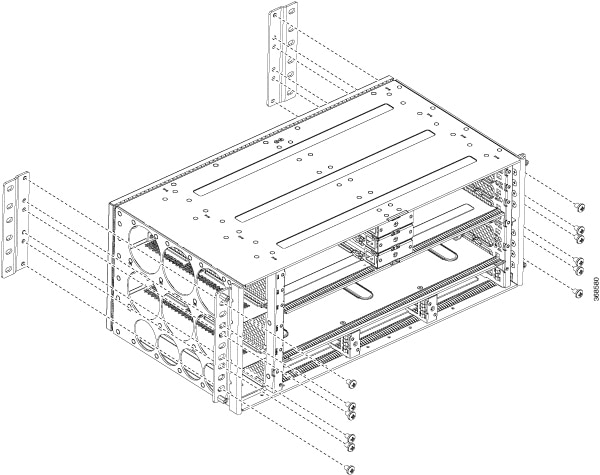
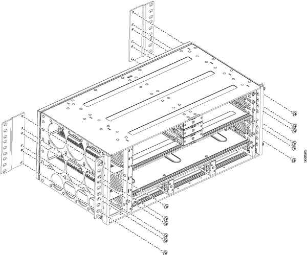
The following figures shows how to attach the brackets on the Cisco NCS 560-4 Router for a ETSI rack and a 23-inch EIA rack.
Figure 1. Installing the Mounting Brackets for n ETSI Rack
Figure 2. Installing the Mounting Brackets for the 23-inch EIA Rack
Step 4
Position the chassis in the rack as follows:
If the front of the chassis (front panel) is at the front of the rack, insert the rear of the chassis between the mounting
posts.
If the rear of the chassis is at the front of the rack, insert the front of the chassis between the mounting posts.
Step 5
Align the mounting holes in the bracket with the mounting holes in the equipment rack.
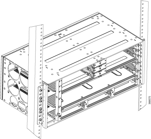
Do not use interface module and power supply ejector handles to lift the chassis; using the handles to lift the chassis can
deform or damage the handles.
Figure 3. Mounting the Router on a 19-inch EIA Rack
Note
The router can be mounted in an ETSI rack but the required bend radius for the cables and fibers within the 300 mm ETSI specification
cannot be maintained.
If you want to mount the router in ETSI cabinets, you need to have a custom-made cabinet front door to meet the fiber bend
radius requirement.
Step 6
Install the 8 or 12 (4 or 6 per side) 12-24 x 3/4-inch or 10-32 x 3/4-inch screws through the holes in the bracket and into
the threaded holes in the equipment rack posts.
Step 7
Use a tape measure and level to verify that the chassis is installed straight and level.
Assembling the Plenum (N560-4-F2B-AIR-U=)
The plenum allows the air around the router to be distributed evenly.
Note
If a plenum is to be installed on the rack, ensure that it is first assembled before it is mounted on the rack.
Note
Installing the chassis in a plenum changes the air flow direction from right-to-left of router to front-to-back of the router.
Procedure
Step 1
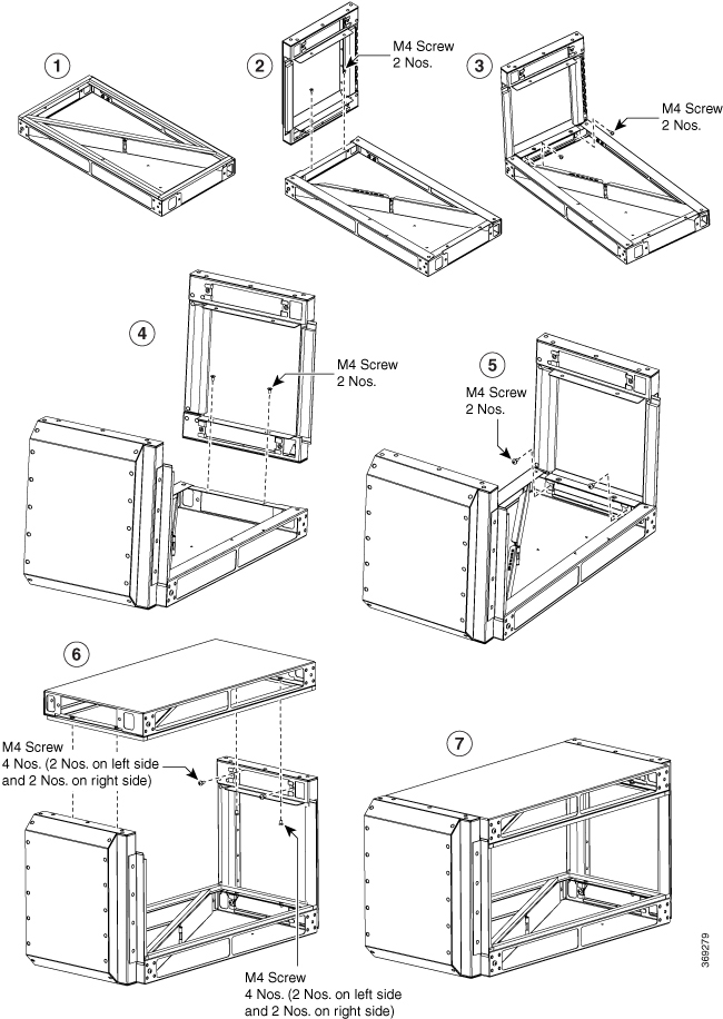
Refer to the figures below to assemble the plenum. Secure all screws using a torque of 11.5 in.-lb (1.3 N-m).
Figure 4. Assembling the Plenum
Step 2
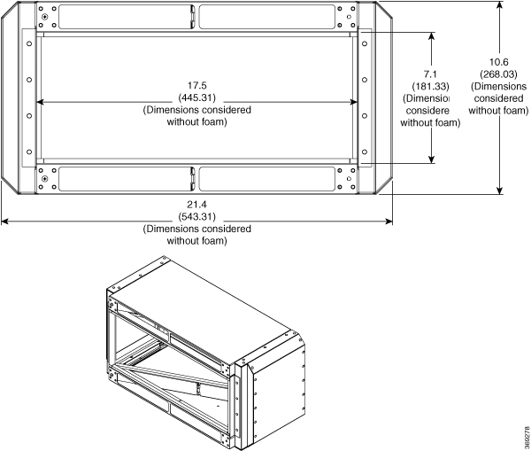
The assembled plenum has the dimensions as shown in the figure below.
Figure 5. Dimensions of the Assembled Plenum
Installing the Plenum on the Rack When Router is Not Installed on the Rack
This procedure talks about installing the plenum when the router is not installed on the rack.
Procedure
Step 1
Identify the correct brackets to the plenum.
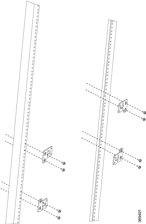
Step 2
Depending on the rack on which you are installing the plenum, identify the appropriate screws to the plenum as shown in the
figures below.
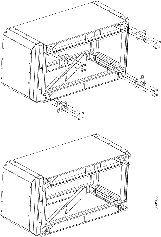
Figure 6. Plenum Brackets for Installation on 19-inch Rack
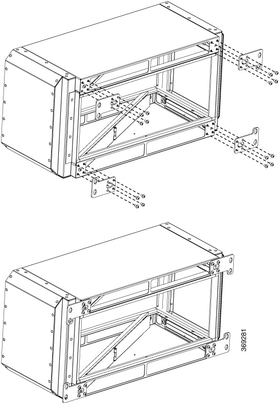
Figure 7. Plenum Brackets for Installation on 21-inch Rack
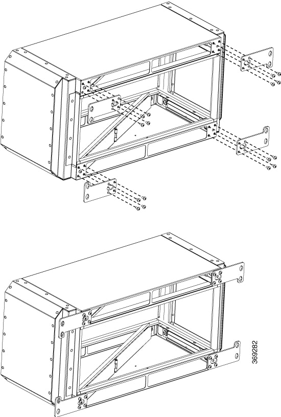
Figure 8. Plenum Brackets for Installation on 23-inch Rack
Step 3
Secure the plenum using appropriate bracket on the rack.
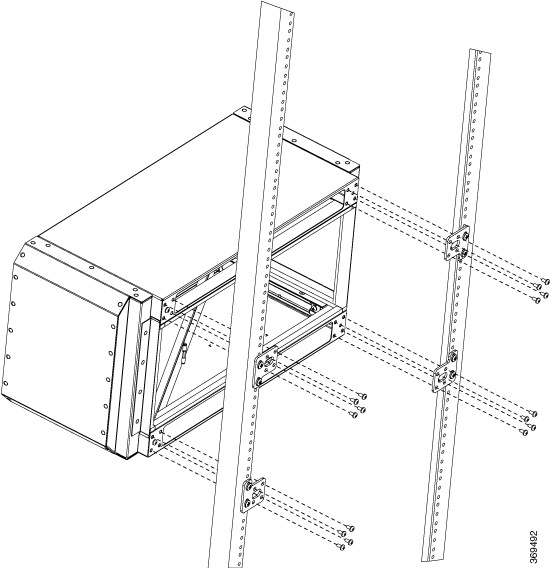
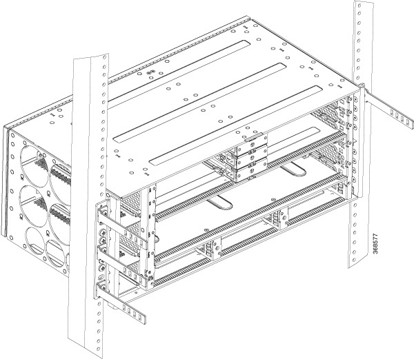
Step 4
Install the router in the plenum as shown in the figure below.
Figure 9. Assembling the Plenum and Router on the Rack
Ensure that the rack post flange dimensions are maintaned as shown in the figure below.
Figure 10. Rack Post Flange Dimensions
Installing the Plenum on the Rack When Router is Installed on the Rack
This procedure talks about installing the plenum when the router is already installed on the rack.
Procedure
Step 1
Identify the type of rack (19-inch, 21-inch, or 23-inch) on which the router is already installed.
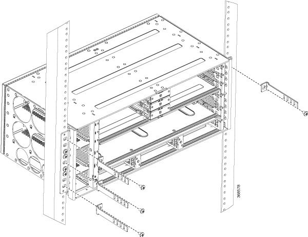
Step 2
Use the assembled plenum as as shown in the figure below.
Step 3
Use the appropriate bracket for the rack and attach the brackets.
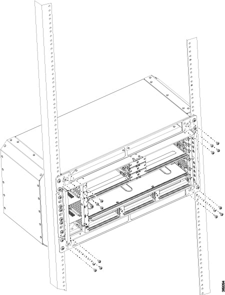
Figure 11. Attaching the Brackets on the Rack
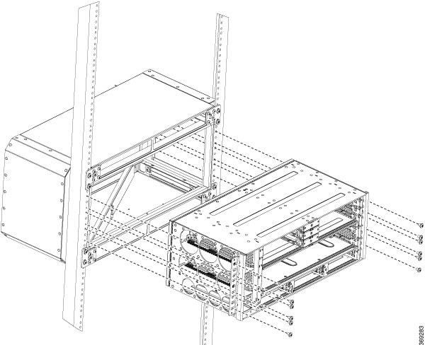
Step 4
Slide the plenum over the router as shown in the figure below.
Step 5
Using the screws that came with the bracket, secure the plenum to the rack.
Figure 12. Installing the Plenum Around the Router
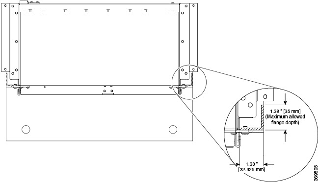
Ensure that the rack post flange dimensions are maintaned as shown in the figure below.
Figure 13. Rack Post Flange Dimensions
Attaching the Cable Management Brackets
The router supports the following bracket:
N560-4-CAB-BRCKT —This bracket helps in routing the cables from the interface modules, router switch processors (RSPs), and
power supply units; thereby enabling a proper cable bending radius.
Note
You can install the cable brackets along with the rack mount screws while installing the chassis. Or, you can install the
cable brackets after the chassis is monted on the rack. However, ensure the brackets are positioned such that they aid cable
routing and provide enough slack for fan trays and air filter removal.
Procedure
Step 1
Position the cable management brackets against the front of the chassis and align the four screw holes, as shown in the figure
below.
Figure 14. Attaching Cable Management Brackets to the 19-inch Rack
Step 2
Secure the cable management brackets with four M4 screws. The recommended maximum torque is 10 in.-lb (1.12 N-m).
Installing the Chassis Ground Connection
Before you connect the power or turn on the power to the Cisco NCS 560-4 Router, you must provide an adequate chassis ground
(earth) connection to your router.
This section describes how to ground the Cisco NCS 560-4 Router. The router provides two locations for attaching a 2-hole
grounding lug according to the rack-mounting brackets you use to install the router.
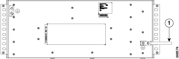
Figure 15. Attaching a Grounding Lug to the Rear of the Router
1
Grounding lug
To ensure that the chassis ground connection that you provide is adequate, you need the following parts and tools:
Ratcheting torque screwdriver with Phillips head that exerts up to 20 in.-lb (2.25 N-m) of pressure for attaching the ground
wire to the router
Crimping tool as specified by the ground lug manufacturer
8 AWG copper wire for the power cord
6 AWG or larger copper wire for the ground wire
Wire-stripping tools appropriate to the wire you are using
Caution
Before making connections to the Cisco NCS 560-4 Router, ensure that you disconnect the power at the circuit breaker. Otherwise,
severe injury to you or damage to the router may occur.
Warning
This equipment must be grounded. Never defeat the ground conductor or operate the equipment in the absence of a suitably
installed ground conductor. Contact the appropriate electrical inspection authority or an electrician if you are uncertain
that suitable grounding is available. Statement 1024
Warning
Use copper conductors only. Statement 1025
Warning
When installing the unit, the ground connection must always be made first and disconnected last. Statement 42
This unit is to be installed in a restrictive access location and must be permanently grounded to minimum 6 AWG copper ground
wire.
Perform the following procedure to ground the router using a 2-hole lug and the corresponding mounting point. Most carriers
require a minimum 6 AWG ground connection. Verify your carrier’s requirements for the ground connection.
Procedure
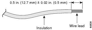
Step 1
If your ground wire is insulated, use a wire-stripping tool to strip the ground wire to 0.5 inch ± 0.02 inch (12.7 mm ±0.5
mm) As shown in the figure below.
Figure 16. Stripping a Ground Wire
Step 2
Slide the open end of your 2-hole ground lug over the exposed area of the ground wire.
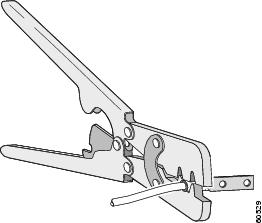
Step 3
Using a crimping tool (as specified by the ground lug manufacturer), crimp the ground lug to the ground wire as shown in
figure below.
Figure 17. Crimping a Ground Lug onto the Ground Wire
Step 4
Use a Phillips head screwdriver to attach the 2-hole ground lug and wire assembly to the router with the 2 pan-head Phillips
head screws. For all racks, attach the 2-hole ground lug to the rear of the router.
Step 5
Connect the other end of the ground wire to a suitable grounding point at your site.
Installing the Power Supply
The Cisco NCS 560-4 Router router provides the choice of three different power supplies—two DC power supplies and one AC
power supply:
1200 W DC power (N560-PWR1200-D-E and A900-PWR1200-D): - 40.8VDC to -72VDC
The A900-PWR1200-D DC power supply uses 3 position terminal block-style connector with positive latching/securing and labeled
connections for RTN and 48V.
The N560-PWR1200-D-E DC power supply uses 2 position terminal block-style connector with positive latching/securing and labeled
connections for RTN and 48V.
The terminal block connector is of suitable size to carry the appropriate AWG wire size (6AWG to 14 AWG) to handle the input
current of the power supply. No ON/OFF switch is provided.
AC power (A900-PWR1200-A): 85VAC to 264VAC
The AC power supply has an IEC-320-C21-type power receptacle and a 20 A service connector. You can use standard right-angle
power cords with the AC power supply. The power supply includes a power cord retainer. No ON/OFF switch is provided.
Caution
Unseat the power supply partially so that there is enough space to open the terminal block cover. Ensure the branch circuit
breaker is turned off. Only after installing the power supply in the chassis, should the branch circuit breaker be turned
on. The branch circuit breaker must be turned off before unplugging the power supply.
Each power supply provides a single primary input power connection. The router supports (2+1) redundancy.
Warning
Read the installation instructions before connecting the system to the power source. Statement 10
Note
Products that have an AC power connection are required to have an external surge protective device (SPD) provided as part
of the building installation to comply with the Telcordia GR-1089 NEBS standard for electromagnetic compatibility and safety.
Caution
Do not use interface module and power supply ejector handles to lift the chassis; using the handles to lift the chassis can
deform or damage the handles.
Preventing Power Loss
Use the following guidelines to prevent power loss to the router.
To prevent loss of input power, ensure that the total maximum load on each circuit supplying the power supplies is within
the current ratings of the wiring and breakers.
In some systems, you can use an UPS to protect against power failures at your site. Avoid UPS types that use ferroresonant
technology. These UPS types can become unstable with systems like the Cisco NCS 560-4 Router, which can have substantial current
draw fluctuations due to bursty data traffic patterns.
Use the information in the DC Power Supply Specifications table to estimate the power requirements and heat dissipation of
a Cisco NCS560-4 Router based on a given configuration of the router. Determining power requirements is useful for planning
the power distribution system needed to support the router.
Power Connection Guidelines
This section provides guidelines for connecting the Cisco NCS 560-4 Router power supplies to the site power source.
Warning
Never defeat the ground conductor or operate the equipment in the
absence of a suitably installed ground conductor. Contact the appropriate
electrical inspection authority or an electrician if you are uncertain that
suitable grounding is available. Statement 213
Warning
The plug-socket combination must be accessible at all times because
it serves as the main disconnecting device. Statement 1019
Note
The above statement is applicable only to the AC power supplies.
Warning
This product requires short-circuit (overcurrent) protection, to be
provided as part of the building installation. Install only in accordance with
national and local wiring regulations. Statement 1045
Guidelines for DC-Powered Systems
Basic guidelines for DC-powered systems include the following:
Each chassis power supply should have its own dedicated input power source. The source must comply with the safety extra-low
voltage (SELV) requirements in the UL 60950, CSA 60950, EN 60950, and IEC 60950 standards.
The circuit must be protected by a dedicated two-pole circuit breaker. The circuit breaker should be sized according to the
power supply input rating and local or national code requirements.
The circuit breaker is considered the disconnect device and should be easily accessible.
The system ground is the power supply and chassis ground.
Do not connect the DC return wire to the system frame or to the system grounding equipment.
Use the grounding lug to attach a wrist strap for ESD protection during servicing.
Guidelines for AC-Powered Systems
Basic guidelines for AC-powered systems include the following:
Each chassis power supply should have its own dedicated branch circuit.
The circuit breaker should be sized according to the power supply input rating and local or national code requirements.
The AC power receptacles used to plug in the chassis must be the grounding type. The grounding conductors that connect to
the receptacles should connect to protective earth ground at the service equipment.
Installing the N560-PWR1200-D-E DC Power Supply Module
The following sections describe how to install a DC power supply in the Cisco NCS 560-4 Router:
Note
This equipment is suitable for installation in Network Telecommunications Facilities and locations where the NEC applies.
Note
The grounding architecture of this product is DC-Isolated (DC-I) for DC-powered products. DC-powered products have a nominal
operating DC voltage of 48 VDC.
Perform the
following procedure to install the power supply module:
Procedure
Step 1
Ensure that the system (earth) ground connection has been made. For ground connection installation instructions, see the
Installing the Chassis Ground Connection section.
Step 2
Slip on the ESD-preventive wrist strap that was included in the accessory kit.
Step 3
If necessary,
remove the blank power supply filler plate from the chassis power supply bay
opening by loosening the captive installation screws.
Step 4
Verify that
power to the DC circuit connected to the power supply you are installing is
off. To ensure that power has been removed from the DC circuits, locate the
circuit breakers for the DC circuits, switch the circuit breakers to the OFF
position, and tape the circuit-breaker switches in the OFF position.
Note
The power supplies do not have a power switch. This step is performed at the power input end.
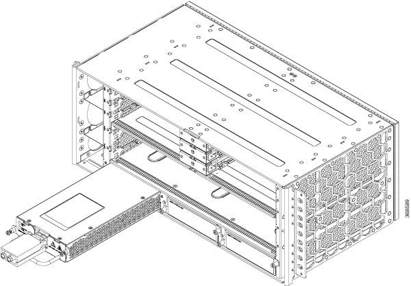
Step 5
Grasp the power supply handle with one hand. Place your other hand underneath the power supply. Slide the power supply into
the power supply slot, but do not seat the power supply completely. Provide ample room for the terminal block cover to be
opened completely for the installation of the lugs.
Figure 18. Inserting the N560-PWR1200-D-E Power Supply
Step 6
Locate the terminal block plug on the power supply unit.
Step 7
Flap open the front protective cover on the power supply unit.
Step 8
Use a wire-stripping tool to strip the ends of each of the two wires coming from the DC-input power source as recommended
by the lug manufacturer. See steps 1 to 3 of Installing the Chassis Ground Connection for information on stripping and crimping the ground wires.
Note
Stripping more than the recommended amount of wire can leave behind exposed wire from the terminal block after installation.
Step 9
Identify the positive and negative feed positions for the terminal block. The recommended wiring sequence is to connect the
negative lead wire and then the positive lead wire.
Step 10
Attach the lugs on the terminal block, as shown in the figure below.
Figure 19. Wiring Sequence and Attaching the Lugs
Caution
Do not over torque the fasteners of the terminal block. The recommended maximum torque is 25 in.-lb (2.82 N-m).
Step 11
Use a tie wrap to secure the wires to the rack, so that the wires are not pulled from the terminal block by casual contact.
Make sure the tie wrap allows for some slack in the wire.
Step 12
Slide the power supply completely until it is firmly seated.
If you are installing a redundant DC power supply, repeat these steps for the second power source.
Installing the A900-PWR1200-D DC Power Supply Module
The following tools are required:
Cables of suitable gauge required for each type of PSU
10 AWG to 16 AWG for 550 W PSU
8 AWG to 10 AWG for 1200 W PSU
Lugs fork-type or ring-type (Burndy—TP10 -6 or TP10-8F (recommended)
Procedure
Step 1
Follow the steps to remove the power supply unit if installed in the chassis. See the Removing and Replacing the DC Power Supply section.
Step 2
Slip on the ESD-preventive wrist strap that was included in the accessory kit.
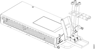
Step 3
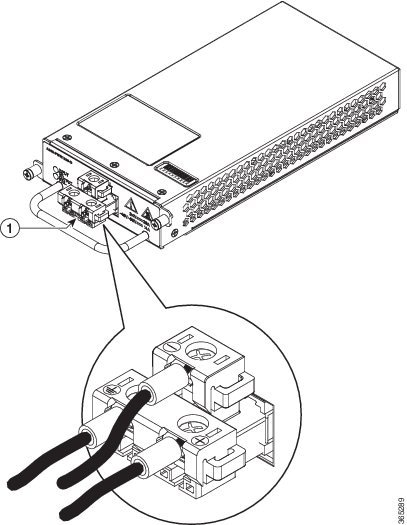
Locate the T-shaped terminal block plug on the DC power supply unit. See the figure below.
Figure 20. A900-PWR1200-D DC Power Supply
1
T-shaped connector
—
—
Step 4
Use a wire-stripping tool to strip the ends of each of the two wires coming from the DC-input power source to 0.27 inch (6.6
mm) ± 0.02 inch (0.5 mm) and the wire for grounding. Do not strip more than 0.29 inch (7.4 mm) of insulation from the wire.
Stripping more than the recommended amount of wire can leave behind exposed wire from the terminal block after installation.
Step 5
Use the appropriate crimping tool as suggested by the manufacture.
Step 6
Prepare the cables by attaching the lugs to the cables.
Step 7
Identify the ground, positive, and negative feed positions for the terminal block connection. The recommended wiring sequence
is:
Negative (-) lead wire (top)
Ground lead wire (left)
Positive (+) lead wire (right)
Step 8
Insert the lugged end of the cables to the connector and secure the cables using the captive screws.
Note
The recommended torque for securing the captive screws is 0.7 N-m.
Step 9
Ensure that the terminal block plug is fully seated in the terminal block header on the DC power supply panel.
Step 10
Slide the power supply into the chassis until it is firmly seated.
Activating the DC Power Supply
Procedure
Step 1
Remove the tape from the circuit-breaker switch handle, and restore power by moving the circuit-breaker switch handle to the
On (|) position.
Step 2
Verify power supply operation by checking if the power supply front panel LEDs are in the following states:
INPUT OK LED is green
OUTPUT FAIL LED is green
If the LEDs indicate a power problem, see the Fan Tray LEDs section.
If you are installing a redundant DC power supply, ensure that each power supply is connected to a separate power source to
prevent power loss during a power failure.
If you are installing a redundant DC power supply, repeat these steps for the second power source.
Removing and Replacing the DC Power Supply
This section provides information about removing and replacing the DC power supply in the Cisco NCS 560-4 Router.
Note
The Cisco NCS 560-4 router power supplies are hot-swappable. If you have installed redundant power supply modules, you can
replace a single power supply without interrupting power to the router.
Caution
To avoid erroneous failure messages, allow at least two minutes for the system to reinitialize after a power supply has been
removed or replaced.
Warning
When you install the unit, the ground connection must always be made first and disconnected last. Statement 1046
Warning
Before performing any of the following procedures, ensure that power is removed from the DC circuit. Statement 1003
Warning
Only trained and qualified personnel should be allowed to install, replace, or service this equipment. Statement 1030
Warning
Installation of the equipment must comply with local and national electrical codes. Statement 1074
Follow these steps to remove and replace the DC power supply on the Cisco NCS 560-4 Router:
Before you begin
See the table below for OIR parameters for the power supply.
Table 1. Online Insertion and Removal - Parameters
1 It is not recommended to perform OIR of any module above 40°C ambient
Procedure
Step 1
Before servicing the power supply, switch off the circuit breaker in your equipment area. As an additional precaution, tape
the circuit-breaker switch in the Off position.
Step 2
Slip on the ESD-preventive wrist strap that was included in the accessory kit.
Step 3
Loosen the captive screws on the DC power supply and pull out the power supply partially so that there is enough space to
open the terminal block cover.
Step 4
Open the terminal block cover to unscrew and remove the lugs.
Note
This step does not apply to the A900-PWR1200-D power supply.
Step 5
Grasping the power supply handle with one hand, pull the power supply out from the chassis while supporting it with the other
hand.
Step 6
Replace the DC power supply within 5 minutes. If the power supply bay is to remain empty, install a blank filler plate (Cisco
part number N560-PWR-BLANK) over the opening, and secure it with the captive installation screws.
Installing the AC Power Supply Module for A900-PWR1200-A (1200 W)
Follow these steps to install the power supply module:
Procedure
Step 1
Ensure that the system (earth) ground connection has been made. For ground connection installation instructions, see the
Installing the Chassis Ground Connection section.
Step 2
Slip on the ESD-preventive wrist strap that was included in the accessory kit.
Step 3
If necessary, remove the blank power supply filler plate from the chassis power supply bay opening by loosening the captive
installation screws.
Step 4
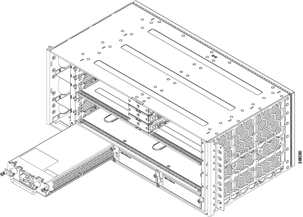
Grasp the power supply handle with one hand. Place your other hand underneath the power supply, as shown in the figure below.
Slide the power supply into the power supply slot. Make sure that the power supply is fully seated in the bay.
Figure 21. Inserting the A900-PWR1200-A Power Supply
Step 5
Tighten the captive installation screws of the power supply. The recommended maximum torque is 5.5 in.-lb (.62 N-m).
Warning
Power supply captive installation screws must be tight to ensure protective grounding continuity.
Recommended Power Cables
Table 2. Power Cable PIDs for A900-PWR1200-A (1200 W)
PID
Description
PWR-CAB-AC-USA520
US AC Power Cord for Cisco ASR 900, NEMA 5-20
PWR-CAB-AC-USA
Power Cord for AC V2 Power Module (USA), NEMA L6-20P
PWR-CAB-AC-AUS
Power Cord for AC V2 Power Module (Australia), AS 3112
PWR-CAB-AC-EU
Power Cord for AC V2 Power Module (Europe), CEE 7/7
PWR-CAB-AC-ITA
Power Cord for AC V2 Power Module (Italy), CEI-23-50
PWR-CAB-AC-SA
Power Cord for AC V2 Power Module (South Africa), SABS 164
PWR-CAB-AC-UK
Power Cord for AC V2 Power Module (UK), EN 60309-2
PWR-CAB-AC-ISRL
Power Cord for AC V2 Power Module (Israel), SI 32
PWR-CAB-AC-CHN
Power Cord for AC V2 Power Module (China), GB2099.1/GB1002
PWR-CAB-AC-BRA
Power Cord for AC V2 Power Module (Brazil), NBR 14136
PWR-CAB-AC-SUI
Power Cord for AC V2 Power Module (Swiss), SEV 1011
PWR-CAB-AC-JPN
Power Cord for AC V2 Power Module (Japan), JIS C8303
PWR-CAB-AC-IND
India AC Power Cord for Cisco ASR 900, IS:1293
PWR-CAB-AC-ARG
AC POWER CORD, WIRE HARNESS, Argentina, IRAM 2073, IEC60320 C21, ST, 4M, 30 AWG, STRANDED, 250.0 V, 16.0 A
Activating the AC Power Supply
Follow these steps to activate the AC power supply:
Procedure
Step 1
Plug the power cord into the power supply.
Step 2
Connect the other end of the power cord to an AC-input power source.
Step 3
Verify power supply operation by checking that the power supply LEDs are in the following states:
INPUT OK LED is green
OUTPUT FAIL LED is green
Step 4
If the LEDs indicate a power problem, see the Troubleshooting for troubleshooting information.
Step 5
If you are installing a redundant power supply, repeat these steps for the second power source.
Note
If you are installing a redundant AC power supply, ensure that each power supply is connected to a separate power source
in order to prevent power loss in the event of a power failure.
Removing and Replacing the AC Power Supply
This section describes how to remove and replace the AC power supply.
Note
The Cisco NCS 560-4 Router power supplies are hot-swappable. If you have installed redundant power supply modules, you can
replace a single power supply without interrupting power to the router.
Caution
To avoid erroneous failure messages, allow at least two minutes for the system to reinitialize after a power supply has been
removed or replaced.
Warning
When you install the unit, the ground connection must always be made first and disconnected last. Statement 1046
Warning
Before performing any of the following procedures, ensure that power is removed from the AC circuit. Statement 1003
Warning
Only trained and qualified personnel should be allowed to install, replace, or service this equipment. Statement 1030
Warning
Installation of the equipment must comply with local and national electrical codes. Statement 1074
Follow these steps to remove and replace the AC power supply:
Before you begin
See the table below for OIR parameters for the power supply.
Table 3. Online Insertion and Removal - Parameters
2 It is not recommended to perform OIR of any module above 40°C ambient
Procedure
Step 1
Disconnect the power cord from the power source. Do not touch the metal prongs on the power cord when it is still connected
to the power supply.
Step 2
Remove the power cord from the power connection on the power supply. Do not touch the metal prongs embedded in the power
supply.
Step 3
Loosen the captive installation screws.
Step 4
Grasp the AC power supply with one hand, and slide it part of the way out of the chassis. Place your other hand underneath
the power supply, and slide it completely out of the chassis.
Step 5
If the power supply bay is to remain empty, install a blank filler plate (Cisco part number N560-PWR-BLANK) over the opening,
and secure it with the captive installation screws.
Installing the Fan Trays
The fan trays are modular units that provides cooling to the Cisco NCS 560-4 Router.
Note
Do not introduce
body parts or objects in the fan tray slot when installing or removing the fan
tray module. Exposed circuitry is an energy hazard.
Follow these steps to install the master fan tray in the chassis:
Procedure
Step 1
Slip on the ESD-preventive wrist strap that was included in the accessory kit.
Step 2
Orient the master fan tray (N560-4-PWR-FAN) so that the captive screws are on the right side of the fan tray’s front panel.
The figure below shows how to orient the fan tray.
Figure 22. Installing the Master Fan Tray (N560-4-PWR-FAN)
Step 3
Guide the master fan tray into the chassis until it is fully seated.
Caution
The fans are exposed on the right side of the fan tray. Keep your fingers, clothing, and jewellery away from the fans. Always
handle the fan tray by the handle.
Step 4
Secure the master fan tray to the chassis using the attached captive installation screws. The recommended maximum torque
is 5.5 in.-lb (.62 N-m).
Step 5
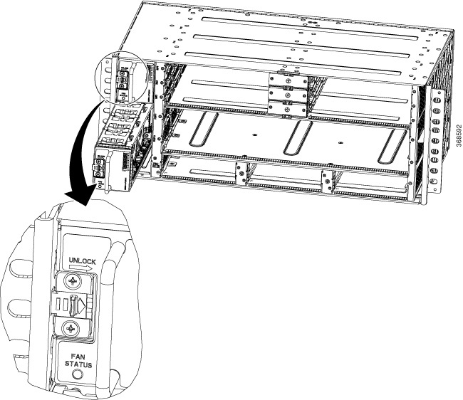
Orient the slave fan tray (N560-4-FAN-H) so that the fan tray is upright. See the figure below.
Figure 23. Installing the Slave Fan Tray (N560-4-FAN-H)
Step 6
Slide the slave fan tray until the snap lock clicks in to place and the fan tray is seated completely.
Step 7
Repeat steps 4 and 5 for the second slave fan tray.
This completes the procedure for installing the fan trays in a Cisco NCS 560-4 Router.
For a summary of the LEDs on the fan tray, see the Pinout and LED Details section. For more information about air flow guidelines, see the Air Flow Guidelines section.
Removing and Replacing the Dust Filter
The chassis is shipped with two blank fan filter covers with the same product identifier (N560-4-FILTER). To install the
dust filter:
Before you begin
If the cables from the interface modules on the right of the chassis cross over the dust filters, gently lift the cables to
clear enough space to remove the dust filters from the chassis.
Procedure
Step 1
Slip on the ESD-preventive wrist strap that was included in the accessory kit.
Step 2
Pull out the blank fan filter covers (N560-4-FILTER).
Step 3
Slide the new dust filters (N560-4-FILTER) onto the fan tray as shown in the figure below.
Figure 24. Dust Filter
Note
The dust filter is a sungle-use component.
Dust Filter Maintenance
A periodic health check of the filter, every 3 months based on the level of dust in the environment, helps in avoiding over
clogging of the filters and provides a better life. This product's filter is used as a single-use component. If the product
is installed in a controlled environment, check and replace the filter every three months, otherwise replace the filter every
month with PID (N560-4-FILTER=) or equivalent.
Removing and Replacing the Fan Trays
This section describes the removal and replacement of both, the master fan tray and the slave fan trays.
When any fan tray is removed, the other fans run at maximum speed. When a fan tray is re-inserted in the chassis, all fans
run at normal speed within two minutes.
Note
If a fan tray is removed and not replaced within the stipulated time the system will automatically power-off. There should
be a minimum time period of 15 seconds between fan tray removal and re-insertion of the fan trays during the operation of
the system. See the OIR section.
Note
Ensure that you keep your fingers, clothing, and jewelry away from the fans when installing or removing the fan tray module.
Exposed circuitry is an energy hazard.
Caution
To avoid erroneous failure messages, allow at least two minutes for the system to reinitialize after the fan tray has been
replaced.
Before you begin
To remove the master fan tray when the cables from the power supplies cross over and across the fan tray, gently lower the
cables to clear enough space and remove the fan tray from the chassis as mentioned in steps 1–4.
To remove the slave fan tray when the cables from the interface module and the RSP cross over and across the fan trays, gently
lift the cables to clear enough space and remove the fan trays from the chassis as mentioned in steps 5–8.
Table 4. Online Insertion and Removal - Parameters
3 It is not recommended to perform OIR of any module above 40°C ambient
4 Fan Tray OIR should be performed only when a fan's failed condition is encountered and other fans are spinning at max speed.
Procedure
Step 1
Slip on the ESD-preventive wrist strap that was included in the accessory kit.
Step 2
Using a No. 2 Phillips screwdriver, loosen the captive installation screw that secures the master fan tray to the router.
Step 3
Grasp the fan tray handle of the master fan tray (N560-4-FAN) with one hand and the outside of the chassis with the other
hand.
Caution
The fans are exposed on the right side of the fan tray. Keep your fingers, clothing, and jewelry away from the fans. Always
handle the fan tray by the handle.
Step 4
Pull the fan tray toward you no more than 1 inch to disengage it from the power receptacle on the midplane.
Step 5
Wait at least 5 seconds to allow the fans to stop spinning. Then, pull the fan trayrout toward you and out of the router.
Note
As the fan tray slides out of the chassis, support the bottom of the fan tray with one hand and keep your other hand on the
fan tray handle.
Note
The chassis must not be allowed to operate without functioning fans for more than 5 minutes.
Step 6
To remove the slave fan tray (N560-4-FAN-H), move the UNLOCK slider to the right to unlocl the slave fan tray from the router.
Step 7
Grasp the slave fan tray handle with one hand and the outside of the chassis with the other hand.
Step 8
Pull the fan tray toward you no more than 1 inch to disengage it from the power receptacle on the midplane.
Step 9
Wait at least 5 seconds to allow the fans to stop spinning. Then, pull the fan tray toward you and out of the router.
Note
As the fan tray slides out of the chassis, support the bottom of the fan tray with one hand and keep your other hand on the
fan tray handle.
This completes the steps for removing the fan tray from the chassis.
This section describes the installation and removal of the RSP.
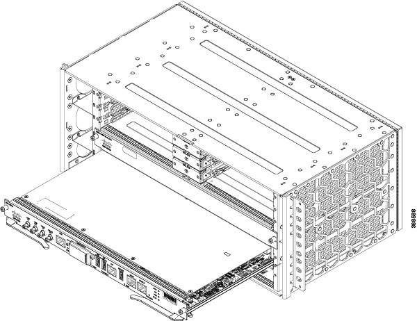
Installing an RSP Module
To install an RSP module in the router chassis, perform the following steps:
Procedure
Step 1
Slip on the ESD-preventive wrist strap that was included in the accessory kit.
Step 2
Choose a slot for the module. Make sure that there is enough clearance to accommodate any equipment that will be connected
to the ports on the module. If a blank module filler plate is installed in the slot in which you plan to install the module,
remove the plate by removing its 2 Phillips pan-head screws.
Step 3
Fully open both the ejector levers on the new module.
Caution
To prevent ESD damage, handle modules by carrier edges only.
Step 4
Position the module in the slot. Make sure that you align the sides of the module with the guides on each side of the slot,
as shown in the figure below.
Figure 25. RSP Installation
Step 5
Carefully slide the module into the slot until the EMI gasket on the module makes contact with the module in the adjacent
slot and both the ejector levers have closed to approximately 45 degrees with respect to the module faceplate.
Caution
If the top slot already has an RSP module installed, and you install a second RSP module in the slot below it, be careful
not to damage the EMI gasket of the bottom RSP module against the ejector levers of the top RSP during insertion.
Step 6
While pressing down, simultaneously close both the ejector levers to fully seat the module in the backplane connector. The
ejector levers are fully closed when they are flush with the module faceplate.
Step 7
Tighten the two captive installation screws on the module. The recommended maximum torque is 5.5 in.-lb (.62 N-m).
Note
Make sure that the ejector levers are fully closed before tightening the captive installation screws.
Step 8
Verify that the captive installation screws are tightened on all of the modules installed in the chassis. This step ensures
that the EMI gaskets on all the modules are fully compressed in order to maximize the opening space for the new or replacement
module.
Note
If the captive installation screws are loose, the EMI gaskets on the installed modules will push adjacent modules toward
the open slot, which reduces the size of the opening and makes it difficult to install the new module.
Caution
Blank module filler plates (Cisco part number N560-4-RSP-BLANK) should be installed in any empty chassis slots to keep dust
out of the chassis and to maintain consistent airflow through the chassis.
Note
When installing the cabling to an RSP, we recommend that you leave a service loop of extra cabling sufficient to allow for
fan tray removal.
Note
Close all unused RJ-45 and USB ports on the RSP module using the appropriate dust caps to prevent dust from accumulating
inside the cage. For information on dust caps, see the Installing Dust Caps section.
Removing an RSP Module
Before you remove an RSP from the router, you should save the current configuration on a TFTP server or an external USB flash
drive, using the copyrunning-config {ftp| tftp| harddisk:} command. This saves you time when bringing the module back online.
Warning
Hazardous voltage or energy is present on the backplane when the system is operating. Use caution when servicing. Statement
1034
Warning
Invisible laser radiation may be emitted from disconnected fibers or connectors. Do not stare into beams or view directly
with optical instruments. Statement 1051
To remove an RSP module:
Before you begin
See the table below for the OIR parameters for RSPs.
Table 5. Online Insertion and Removal - Parameters
5 It is not recommended to perform OIR of any module above 40°C ambient
Procedure
Step 1
Slip on the ESD-preventive wrist strap that was included in the accessory kit.
Step 2
Disconnect any cables attached to the ports on the module.
Step 3
Verify that the captive installation screws on all the modules in the chassis are tight. This step ensures that the space
created by the removed module is maintained.
Note
If the captive installation screws are loose, the EMI gaskets on the installed modules will push the modules toward the open
slot, which in turn reduces the size of the opening and makes it difficult to remove the module.
Step 4
Loosen the two captive installation screws on the module you plan to remove from the chassis.
Step 5
Place your thumbs on the ejector levers (see ) and simultaneously rotate the ejector levers outward to unseat the module
from the backplane connector.
Step 6
Grasp the front edge of the module and slide the module straight out of the slot. If the chassis has horizontal slots, place
your hand under the module to support its weight as you slide it out from the slot. Do not touch the module circuitry.
Caution
To prevent ESD damage, handle modules by the carrier edges only.
Step 7
Place the module on an antistatic mat or antistatic foam, or immediately reinstall the module in another slot.
Step 8
Install blank module filler plates (Cisco part number N560-4-RSP-BLANK) in empty slots, if any.
Warning
Blank faceplates and cover panels serve three important functions: they prevent exposure to hazardous voltages and currents
inside the chassis; they contain electromagnetic interference (EMI) that might disrupt other equipment; and they direct the
flow of cooling air through the chassis. Do not operate the system unless all cards, faceplates, front covers, and rear covers
are in place. Statement 1029
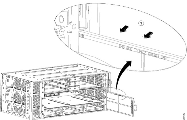
Removing the IM Center Brackets
The IM center brackets are already installed in the chassis. They allow for installing two interface modules of half-width
side-by-side. By removing the IM center bracket, full-width Interface Modules with higher capacity and interface density can
be installed in the chassis.
Procedure
Step 1
Slip on the ESD-preventive wrist strap that was included in the accessory kit.
Step 2
Grasp the IM center bracket from its sides and slide it straight out of its slot.
Figure 26. Removing the IM Center Bracket from the IM Slot
This completes the removal of the IM center brackets.
Interface Module Installation
The following sections describe the various tasks associated with interface module installation on the Cisco NCS 560-4 Router:
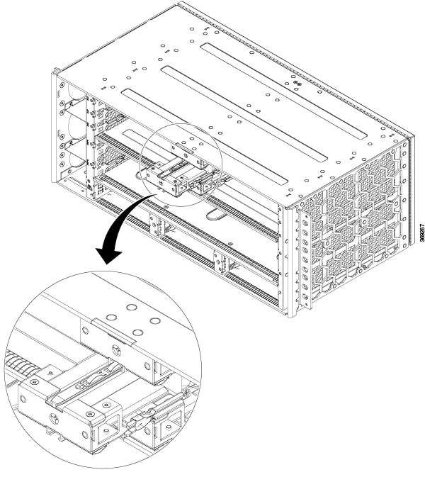
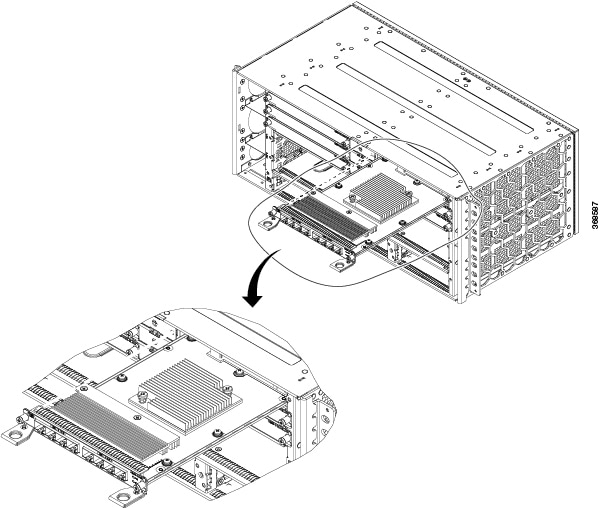
Installing an Interface Module
Procedure
Step 1
Slip on the ESD-preventive wrist strap that was included in the accessory kit.
Step 2
Before inserting an interface module (IM), make sure that the chassis is grounded.
Step 3
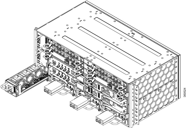
To insert the IM, carefully align the edges of the IM between the upper and lower edges of the IM slot.
Step 4
Carefully slide the IM into the slot until the IM makes contact with the backplane.
Figure 27. Inserting an Interface Module
Step 5
Tighten the locking thumbscrews on both sides of the interface module. The recommended maximum torque is 5.5 in.-lb (.62 N-m).
Step 6
Connect all the cables to each interface module when ready for test and turn-up.
Caution
Do not use interface module and power supply ejector handles to lift the chassis; using the handles to lift the chassis can
deform or damage the handles
Note
Close all unused RJ-45, SFP, XFP, and QSFP ports on the interface module using the appropriate dust caps to prevent dust from
accumulating inside the cage. For information on dust caps, see Installing Dust Caps .
Removing an Interface Module
Procedure
Step 1
Slip on the ESD-preventive wrist strap that was included in the accessory kit.
Step 2
To remove an interface module, disconnect all the cables from each interface module.
Step 3
Loosen the locking thumbscrews on both sides of the interface module.
Step 4
Slide the interface module out of the IM slot by pulling on the handles. If you are removing a blank filler plate, pull the
blank filler plate completely out of the IM slot using the captive screws.
Hot-Swapping an RSP or Interface Module
The Cisco NCS 560-4 Router provides a feature that allows you to remove and replace a redundant RSP module without powering
down the router. This feature, called hot-swapping or OIR, allows you to remove and replace a redundant module without disrupting
router operation.
When two redundant modules are installed in the router, only one of the modules is active. The other one runs in standby mode,
ready to take over processing if the active module fails.
When you remove or insert a redundant module while the router is powered on and running, the router does the following:
Determines if there is sufficient power for the module.
Scans the backplane for configuration changes.
Initializes the newly inserted module. In addition, the system notes any removed modules and places those modules in the administratively
shutdown state.
Places any previously configured interfaces on the module back to the state they were in when they were removed. Any newly
inserted interfaces are put in the administratively shutdown state as if they were present (but unconfigured) at boot time.
If you insert the same type of module into a slot, its ports are configured and brought online up to the port count of the
original module.
The router runs diagnostic tests on any new interfaces and the test results indicate the following:
If the tests pass, the router is operating normally.
If the new module is faulty, the router resumes normal operation but leaves the new interfaces disabled.
If the diagnostic tests fail, the router stops operating, which usually indicates that the new module has a problem in the
bus and should be removed.
Use the following guidelines when performing an OIR on an IM:
Allow at least two minutes for the system to reinitialize before inserting a new IM.
Avoid inserting a new IM during bootup until the active and standby RSPs have reached an OK state.
When inserting multiple IMs into the chassis, wait until each IM reaches an OK state before inserting the next IM.
Installing Dust Caps
The following list provides the product IDs (PIDs) for the dust caps that are available for each port type:
RJ-45—A900-DCAP-RJ45-S= (24 dust caps per package) or A900-DCAP-RJ45-L= (240 caps per package)
SFP—A900-DCAP-SFP-S= (24 caps per package) or A900-DCAP-SFP-L= (240 caps per package)
USB—A900-DCAP-USB-S= (12 dust caps per package) or A900-DCAP-USB-L= (120 dust caps per package)
XFP/QSFP—A900-DCAP-XFP-S= (12 dust caps per package) or A900-DCAP-XFP-L= (120 dust caps per package)
To install the dust cap:
Hold the dust cap by its handle.
Insert the dust cap in to the appropriate unused ports (RJ-45, SFP, USB, or XFP/QSFP) on the chassis front panel.
Securing the Cables Around the Cable Management Brackets
Procedure
Step 1
Gather cables from the interface modules (IM) on the left side of the chassis and secure them with velcro. Repeat this process
with the IMs s on the right side, the cables from the RSPs and the cables from the power supply units.
Step 2
Secure the cables around the cable management brackets as shown in the figures below.
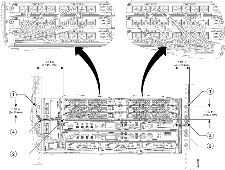
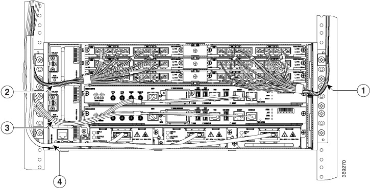
Figure 28. Gathering and Securing the Cables - Front View
1
Point A
2
Point B
3
Curved cable length 95mm from point A to point B
4
Curved cable length 120mm from point A to point B
1
Cables from the interface modules on the right side of chassis
2
Cables from the interface modules on the left side of chassis
3
Cables from the active and standby RSPs
4
Cables from the active and standby RSPs
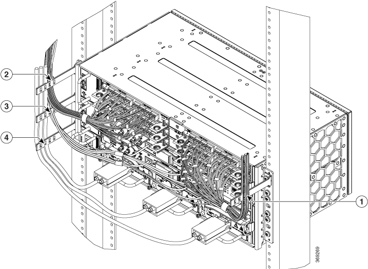
Figure 29. Securing the Cables – Side View
1
Position of the IM Card cables (dust filter side) on the cable management bracket
2
Position of the IM Card cables (fan tray side) on the cable management bracket
3
Postion of the RSP cables on the cable management bracket
4
Postion of the power supply cables on the cable management bracket
Connecting the Router to the Network
This section describes the various ways to connect the router to the network.
Connecting Console Cables
Note
You cannot use the USB and RS232 console ports at the same time; if you insert the USB cable into the router, the RS232 port
is disabled.
Connecting to the Serial Port using Microsoft Windows
This procedure shows how to connect to the serial port using Microsoft Windows.
Note
Install the USB device driver before establishing a physical connection between the router and the PC, by using the USB Console
cable plugged into the USB serial port. Otherwise, the connection will fail. For more information, see the Installing the Cisco Microsoft Windows USB Device Driver.
Procedure
Step 1
Connect the end of the console cable with the RJ45 connector to the light blue console port on the router. or Connect a USB
Type A-to-Type A cable to the USB console port. If you are using the USB serial port for the first time on a Windows-based
PC, install the USB driver now according to the instructions in the following sections.
Installing the Cisco Microsoft Windows Vista USB Driver
Note
You cannot use the USB port and the EIA port concurrently. See Connecting to the Auxiliary Port section. When the USB port is used it takes priority over the RJ45 EIA port.
Note
The USB Type A-to-Type A cable is not included with the Cisco NCS 560-4 Router; it is ordered separately.
Step 2
Connect the end of the cable with the DB-9 connector (or USB Type-A) to the terminal or PC. If your terminal or PC has a
console port that does not accommodate a DB-9 connector, you must provide an appropriate adapter for that port.
Step 3
To communicate with the router, start a terminal emulator application, such as Microsoft Windows HyperTerminal. This software
should be configured with the following parameters:
9600 baud
8 data bits
no parity
1 stop-bit
no flow control
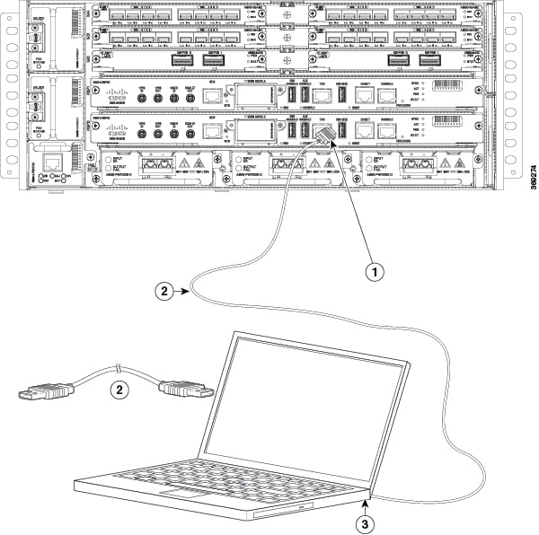
Figure 30. Connecting the USB Console Cable to the Cisco NCS 560-4 Router
1
USB Type-A console port
2
USB 5-pin mini USB Type-B to USB Type-A console cable
3
USB Type-A
—
—
Connecting to the Console Port using Mac OS X
This procedure describes how to connect a Mac OS X system USB port to the console using the built in OS X Terminal utility.
Procedure
Step 1
Use the Finder to go to Applications → Utilities → Terminal.
Step 2
Connect the OS X USB port to the router.
Step 3
Enter the following commands to find the OS X USB port number:
Example:
macbook:user$ cd /dev
macbook:user$ ls -ltr /dev/*usb*
crw-rw-rw-  1 root    wheel       9,  66 Apr  1 16:46 tty.usbmodem1a21 DT-macbook:dev user$
Step 4
Connect to the USB port with the following command followed by the router USB port speed
Example:
macbook:user$ screen /dev/tty.usbmodem1a21 9600
To disconnect the OS X USB console from the Terminal window enter Ctrl-a followed by Ctrl-\.
Connecting to the Console Port using Linux
This procedure shows how to connect a Linux system USB port to the console using the built in Linux Terminal utility.
Procedure
Step 1
Open the Linux Terminal window.
Step 2
Connect the Linux USB port to the router.
Step 3
Enter the following commands to find the Linux USB port number
Example:
root@usb-suse# cd /dev
root@usb-suse /dev# ls -ltr *ACM*
crw-r--r--    1 root     root     188,   0 Jan 14 18:02 ttyACM0
root@usb-suse /dev#
Step 4
Connect to the USB port with the following command followed by the router USB port speed
Example:
root@usb-suse /dev# screen /dev/ttyACM0 9600
To disconnect the Linux USB console from the Terminal window enter Ctrl-a followed by : then quit
Installing the Cisco Microsoft Windows USB Device Driver
A USB device driver must be installed the first time a Microsoft Windows-based PC is connected to the USB serial port on the
router.
Installing the Cisco Microsoft Windows XP USB Driver
This procedure shows how to install the Microsoft Windows XP USB driver. Download the driver for your router model from the
Tools and Resources Download Software site, USB Console Software category, at the following URL:
Unzip the file Cisco_usbconsole_driver_X_X.zip (where X is a revision number).
Step 2
If using 32-bit Windows XP double-click the file setup.exe from the Windows_32 folder, or if using 64-bit Windows XP double-click
the file setup(x64).exe from the Windows_64 folder.
Step 3
The Cisco Virtual Com InstallShield Wizard begins. Click Next.
Step 4
The Ready to Install the Program window appears. Click Install.
Step 5
The InstallShield Wizard Completed window appears. Click Finish.
Step 6
Connect the USB cable to the PC and router USB console ports. The EN LED for the USB console port turns green, and within
a few moments the Found New Hardware Wizard appears. Follow the instructions to complete the installation of the driver.
The USB console is ready for use.
Installing the Cisco Microsoft Windows 2000 USB Driver
This procedure shows how to install the Microsoft Windows 2000 USB driver.
Procedure
Step 1
Obtain the file Cisco_usbconsole_driver.zip from the Cisco.com web site and unzip it.
Step 2
Double-click the file setup.exe.
Step 3
The Cisco Virtual Com InstallShield Wizard begins. Click Next.
Step 4
The Ready to Install the Program window appears, Click Install.
Step 5
The InstallShield Wizard Completed window appears. Click Finish.
Step 6
Connect the USB cable to the PC and router USB console ports. The EN LED for the USB console port turns green, and within
a few moments a series of Found New Hardware Wizard windows appear. Follow the instructions to complete the installation of
the driver.
The USB console is ready for use.
Installing the Cisco Microsoft Windows XP USB Driver
This procedure shows how to install the Microsoft Windows XP USB driver. Download the driver for your router model from the
Tools and Resources Download Software site, USB Console Software category, at the following URL:
Unzip the file Cisco_usbconsole_driver_X_X.zip (where X is a revision number).
Step 2
If using 32-bit Windows XP double-click the file setup.exe from the Windows_32 folder, or if using 64-bit Windows XP double-click
the file setup(x64).exe from the Windows_64 folder.
Step 3
The Cisco Virtual Com InstallShield Wizard begins. Click Next.
Step 4
The Ready to Install the Program window appears. Click Install.
Step 5
The InstallShield Wizard Completed window appears. Click Finish.
Step 6
Connect the USB cable to the PC and router USB console ports. The EN LED for the USB console port turns green, and within
a few moments the Found New Hardware Wizard appears. Follow the instructions to complete the installation of the driver.
The USB console is ready for use.
Uninstalling the Cisco Microsoft Windows USB Driver
This section provides instructions for how to uninstall the Cisco Microsoft Windows USB device driver.
Uninstalling the
Cisco Microsoft Windows XP and 2000 USB Driver Using the Setup.exe
Program
Disconnect the router console terminal before uninstalling the driver.
Procedure
Step 1
Run the setup.exe for Windows 32-bit or setup(x64).exe for
Windows-64bit. Click
Next.
Step 2
The InstallShield Wizard for Cisco Virtual Com appears. Click
Next.
Step 3
When the Program Maintenance window appears, select the Remove
radio button. Click
Next.
Step 4
When the Remove the Program window appears, click
Remove.
Step 5
When the InstallShield Wizard Completed window appears click
Finish.
Uninstalling the Cisco Microsoft Windows XP and 2000 USB Driver Using the Add Remove Programs Utility
Disconnect the router console terminal before uninstalling the driver.
Procedure
Step 1
Click Start → Control Panel → Add or Remove Programs.
Step 2
Scroll to Cisco Virtual Com and click Remove.
Step 3
When the Program Maintenance window appears, select the Remove radio button. Click Next.
Uninstalling the Cisco Microsoft Windows Vista USB Driver
This procedure shows you how to uninstall the Microsoft Windows Vista
USB driver.
Note
Disconnect the router console terminal before uninstalling the
driver.
Procedure
Step 1
Run the setup.exe for Windows 32-bit or setup(x64).exe for Windows-64bit. Click Next.
Step 2
The InstallShield Wizard for Cisco Virtual Com appears. Click Next.
Step 3
When the Program Maintenance window appears, select the Remove radio button. Click Next.
Step 4
When the Remove the Program window appears, click Remove.
Note
If a User Account Control warning appears, click Allow - I trust this program... to proceed.
Step 5
When the InstallShield Wizard Completed window appears click Finish.
Connecting to the Auxiliary Port
When a modem is connected to the auxiliary port, a remote user can dial in to the router and configure it. Use a light blue
console cable and the DB-9-to-DB-25 connector adapter.
Note
The console cable and DB-9-to-DB-25 connector are not included with the Cisco NCS 560-4 Router; they are ordered separately.
To connect a modem to the router, follow these steps:
Procedure
Step 1
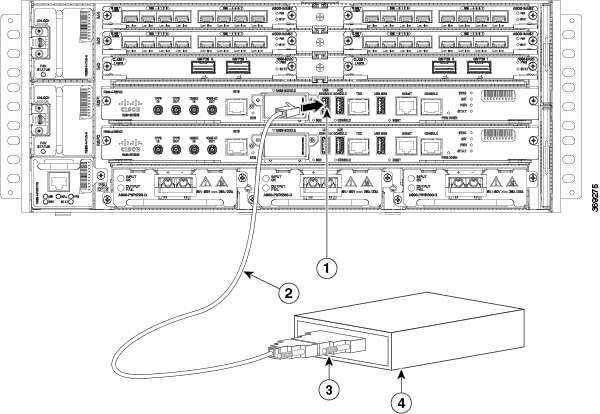
Connect the RJ45 end of the adapter cable to the black AUX port on the router, as shown in the figure below.
Figure 31. Connecting a Modem to the Cisco NCS 560-4 Router
1
RJ45 AUX port
3
RJ45 to DB-9
2
DB-9 to DB-25 adapter
4
Modem
Step 2
Connect the DB-9 end of the console cable to the DB-9 end of the modem adapter.
Step 3
Connect the DB-25 end of the modem adapter to the modem.
Step 4
Make sure that your modem and the router auxiliary port are configured for the same transmission speed (up to 115200 bps
is supported) and for mode control with data carrier detect (DCD) and data terminal ready (DTR) operations.
Connecting a Management Ethernet Cable
When using the Ethernet Management port in the default mode (speed-auto and duplex-auto) the port operates in auto-MDI/MDI-X
mode. The port automatically provides the correct signal connectivity through the Auto-MDI/MDI-X feature. The port automatically
senses a crossover or straight-through cable and adapts to it.
However, when the Ethernet Management port is configured to a fixed speed (10 or 100 Mbps) through command-line interface
(CLI) commands, the port is forced to MDI mode.
When in a fixed-speed configuration and MDI mode:
Use a crossover cable to connect to an MDI port
Use a straight-through cable to connect to an MDI-X port
Warning
To comply with the Telcordia GR-1089 NEBS standard for electromagnetic compatibility and safety, connect the Management Ethernet
ports only to intra-building or unexposed wiring or cable. The intrabuilding cable must be shielded and the shield must be
grounded at both ends. The intra-building port(s) of the equipment or subassembly must not be metallically connected to interfaces
that connect to the OSP or its wiring. These interfaces are designed for use as intra-building interfaces only (Type 2 or
Type 4 ports as described in GR-1089-CORE) and require isolation from the exposed OSP cabling. The addition of Primary Protectors
is not sufficient protection in order to connect these interfaces metallically to OSP wiring.
Installing and Removing SFP Modules
The Cisco NCS 560-4 Router supports a variety of SFP modules, including optical and Ethernet modules. For information on
how to install and remove SFP modules, see the documentation for the SFP module at
We recommend that you wait 30 seconds between removal and insertion of an SFP on an interface module. This time is recommended
to allow the transceiver software to initialize and synchronize with the standby RSP. Changing an SFP more quickly could result
in transceiver initialization issues that disable the SFP.
Connecting a USB Flash Device
To connect a USB flash device to the Cisco NCS 560-4 Router, insert the memory stick in the USB port labeled MEM. The Flash
memory module can be inserted in only one way, and can be inserted or removed regardless of whether the router is powered
up or not.
Removing a USB Flash Device
To remove and then replace a USB flash token memory stick from a Cisco NCS 560-4 Router, follow these steps:
Procedure
Step 1
Pull the memory stick from the USB port.
Step 2
To replace a Cisco USB Flash memory stick, simply insert the module into the USB port labeled USB MEM. The Flash memory module
can be inserted in only one way, and can be inserted or removed regardless of whether the router is powered up or not.
Note
You can insert or remove the memory stick whether the router is powered on or not.
This completes the USB Flash memory installation procedure.
Connecting Timing Cables
The following sections describe how to connect timing cables to the Cisco NCS 560-4 Router:
Note
When installing the cabling to the RSPs, we recommend that you leave a service loop of extra cabling sufficient to allow
for fan tray removal.
Connecting Cables to the BITS Interface
The following steps describe how to connect a cable to the router BITS port:
Procedure
Step 1
Confirm that the router is powered off.
Step 2
Connect one end of the cable to the BITS port using a straight-through, shielded RJ48C-to-RJ48C cable.
Step 3
Connect the other end to the BTS patch or demarcation panel at your site.
Step 4
Turn on power to the router.
For information about the BITS port pinouts, see Troubleshooting.
Note
Use of two BITS sources or a Y-cable is optional. Each BITS input port is routed to both RSPs, so that SETS device on each
RSP has visibility to both BITS inputs.
Warning
To comply with the Telcordia GR-1089 NEBS standard for electromagnetic compatibility and safety, connect the BITS ports only
to intra-building or unexposed wiring or cable. The intrabuilding cable must be shielded and the shield must be grounded at
both ends. The intra-building port(s) of the equipment or subassembly must not be metallically connected to interfaces that
connect to the OSP or its wiring. These interfaces are designed for use as intra-building interfaces only (Type 2 or Type
4 ports as described in GR-1089-CORE) and require isolation from the exposed OSP cabling. The addition of Primary Protectors
is not sufficient protection in order to connect these interfaces metallically to OSP wiring.
Connecting Cables to the Input 10Mhz or 1PPS Interface
Procedure
Step 1
Connect one end of a mini-coax Y-cable to the GPS unit.
Step 2
Connect one end of the split-side Y-cable mini-coax to the 10Mhz or 1PPS port on the primary RSP of the router.
Step 3
Connect the other end of the split-side Y-cable mini-coax to the 10Mhz or 1PPS port on the backup RSP of the router.
Connecting Cables to the Output 10Mhz or 1PPS Interface
Procedure
Step 1
Connect one end of a mini-coax Y-cable to the Slave unit.
Step 2
Connect one end of the split-side Y-cable mini-coax to the 10Mhz or 1PPS port on the primary RSP of the router.
Step 3
Connect the other end of the split-side Y-cable mini-coax to the 10Mhz or 1PPS port on the backup RSP of the router.
Connecting Cables to the ToD Interface
Procedure
Step 1
Connect one end of a straight-through Ethernet cable to the GPS unit.
Step 2
Connect one end of the split-side Y-cable Ethernet to the ToD port on the primary RSP of the router.
Step 3
Connect the other end of the split-side Y-cable Ethernet to the ToD port on the backup RSP of the rRouter.
Note
For instructions on how to configure clocking, see the Network Synchronization Configuration for the Cisco NCS 560 Series Routers.
Warning
To comply with the Telcordia GR-1089 NEBS standard for electromagnetic compatibility and safety, connect the ToD ports only
to intra-building or unexposed wiring or cable. The intrabuilding cable must be shielded and the shield must be grounded at
both ends. The intra-building port(s) of the equipment or subassembly must not be metallically connected to interfaces that
connect to the OSP or its wiring. These interfaces are designed for use as intra-building interfaces only (Type 2 or Type
4 ports as described in GR-1089-CORE) and require isolation from the exposed OSP cabling. The addition of Primary Protectors
is not sufficient protection in order to connect these interfaces metallically to OSP wiring.
Note
For more information about GPS port pinouts, see the LED Details section.
Connecting Cables to a GNSS Interface
The following sections describe how to connect cables from the Cisco NCS 560-4 Router to a GPS unit for input or output timing
of frequency.
Note
A Y-cable is required to connect to a primary and backup RSP in order to ensure that the router continues to transmit timing
signals in the event of a network failure. For a mini-coax connection, this Y-cable can be part number CAB-BNC-7INY (7 inch
BNC Y-cable). For an Ethernet connection, this Y-cable can be a RJ45 Cat5 1-to-2 splitter (3 female port RJ45 connector).
Note
When installing the cabling to the RSPs, we recommend that you leave a service loop of extra cabling sufficient to allow
for fan tray removal.
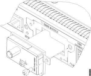
Connecting a Cable to the GNSS Antenna Interface
Note
The GNSS module is not hot swappable.
Procedure
Step 1
Connect one end of a shielded coaxial cable to the GNSS RF IN port.
Step 2
Connect the other end of the shielded coaxial cable to the GNSS antenna after the primary protector.
Note
The GNSS RF In port should have a primary protector installed to meet the Local Safety guidelines.
Note
The GNSS RF In coaxial cable shield must be connected to the Facility Equipment Ground through the chassis. The chassis must
have the ground wire connected to the Facility Equipment Ground.
Figure 32. Inserting the GNSS Module in the RSP
Connecting Ethernet Cables
The interface modules support RJ45 or SFP Ethernet ports. For instructions on how to connect cables to Ethernet SFP ports,
see Connecting Cables to SFP Modules.
The RJ45 port supports standard straight-through and crossover Category 5 unshielded twisted-pair (UTP) cables. Cisco Systems
does not supply Category 5 UTP cables; these cables are available commercially.
Warning
To comply with the Telcordia GR-1089 NEBS standard for electromagnetic compatibility and safety, connect the Gigabit Ethernet
ports only to intra-building or unexposed wiring or cable. The intrabuilding cable must be shielded and the shield must be
grounded at both ends. The intra-building port(s) of the equipment or subassembly must not be metallically connected to interfaces
that connect to the OSP or its wiring. These interfaces are designed for use as intra-building interfaces only (Type 2 or
Type 4 ports as described in GR-1089-CORE) and require isolation from the exposed OSP cabling. The addition of Primary Protectors
is not sufficient protection in order to connect these interfaces metallically to OSP wiring.
Note
When installing the cabling to the RSPs, we recommend that you leave a service loop of extra cabling sufficient to allow
for fan tray removal.
Follow these steps to connect the cable to a copper Gigabit Ethernet port:
Procedure
Step 1
Confirm that the router is powered off.
Step 2
Connect one end of the cable to the Gigabit Ethernet port on the router.
Step 3
Connect the other end to the BTS patch or demarcation panel at your site.
Connecting Cables to SFP Modules
For information on connecting cables to Cisco optical and Ethernet SFP interfaces, see
The Cisco NCS 560-4 Router supports a variety of SFP modules, including optical and Ethernet modules. For information on
how to install and remove SFP modules, see the documentation for the SFP module at
We recommend that you wait 30 seconds between removal and insertion of an SFP on an interface module. This time is recommended
to allow the transceiver software to initialize and synchronize with the standby RSP. Changing an SFP more quickly could result
in transceiver initialization issues that disable the SFP.


 Feedback