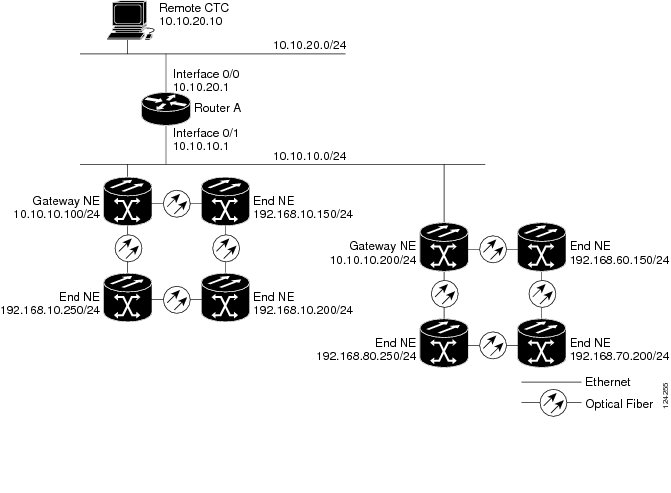
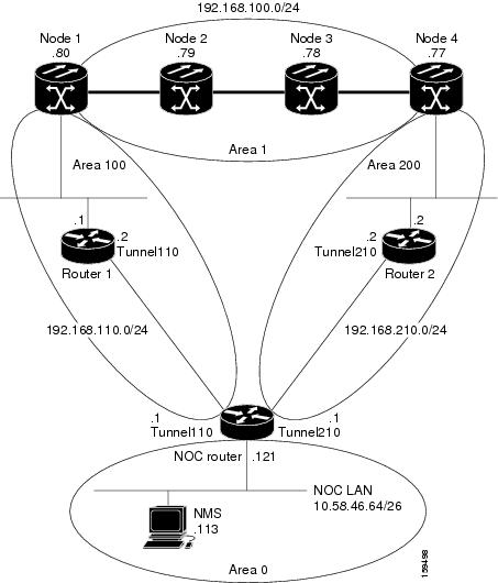
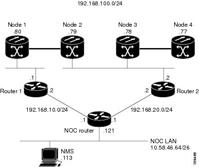
The following sections
provide sample IP configurations at routers and
NCS nodes for
DCN Case Study 3.
NOC Router IP Configuration
Interface configuration:
interface Ethernet0/0
 ip address 10.58.46.121 255.255.255.192
 no ip directed-broadcast
!
interface Ethernet1/0
 ip address 192.168.20.1 255.255.255.0
 no ip directed-broadcast
!
interface Ethernet2/0
 ip address 192.168.10.1 255.255.255.0
 no ip directed-broadcast
!
interface Loopback0
ip address 10.1.1.1 255.255.255.0
no ip directed-broadcast
!
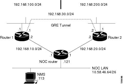
GRE tunnel interface
configuration:
interface Tunnel110
ip address 192.168.110.1 255.255.255.0
tunnel source Ethernet2/0
tunnel destination 192.168.10.2
!
interface Tunnel210
ip address 192.168.210.1 255.255.255.0
tunnel source Ethernet1/0
tunnel destination 192.168.20.2
!
OSPF routing configuration:
router ospf 1
network 10.1.1.0 0.0.0.255 area 0
network 10.0.0.0 0.255.255.255 area 0
network 192.168.110.0 0.0.0.255 area 100
network 192.168.210.0 0.0.0.255 area 200
area 100 virtual-link 192.168.100.80
area 200 virtual-link 192.168.100.77
!

Note
|
The OSPF virtual
link to the end
NCS is created to
connect the DCC/OSC/GCC OSPF area 1 to the backbone area 0. No static routes
are defined on the NOC router.
|
Router 1 IP Configuration
Interface configuration:
interface Ethernet0/0
ip address 192.168.10.2 255.255.255.0
no ip directed-broadcast
!
interface Ethernet1/0
ip address 192.168.100.1 255.255.255.0
no ip directed-broadcast
GRE tunnel interface
configuration:
interface Tunnel110
ip address 192.168.110.2 255.255.255.0
tunnel source Ethernet0/0
tunnel destination 192.168.10.1
!
OSPF and static routing
configuration:
router ospf 1
log-adjacency-changes
network 192.168.100.0 0.0.0.255 area 100
network 192.168.110.0 0.0.0.255 area 100
!
ip classless
ip route 0.0.0.0 0.0.0.0 192.168.10.1
Router 2 IP Configuration
Interface configuration:
interface Ethernet0/0
ip address 192.168.20.2 255.255.255.0
no ip directed-broadcast
!
interface Ethernet1/0
ip address 192.168.100.2 255.255.255.0
no ip directed-broadcast
GRE tunnel interface
configuration:
interface Tunnel210
 ip address 192.168.210.2 255.255.255.0
 tunnel source Ethernet0/0
 tunnel destination 192.168.20.1
!
OSPF and static routing
configuration:
router ospf 1
 network 192.168.100.0 0.0.0.255 area 200
 network 192.168.210.0 0.0.0.255 area 200
!
ip classless
ip route 0.0.0.0 0.0.0.0 192.168.20.1
The following table shows the
network settings on the four
NCS nodes. The static
routes are created so the DCN-connected nodes can advertise their capability to
act as last-resort routers.
Table 7. DCN Case Study 3 Node IP
Addresses
|
Node
|
IP Address/Mask
|
Default Gateway
|
OSPF Configuration
|
|
Node 1
|
192.168.100.80/24
|
192.168.100.1
|
DCC/OSC/GCC area: 0.0.0.1
LAN area: 0.0.0.100
OSPF Area Range Table:
-
192.168.100.79/32 - Area
0.0.0.1
-
192.168.100.78/32 - Area
0.0.0.1
-
192.168.100.77/32 - Area
0.0.0.1
Virtual Link Table: 10.1.1.1
|
|
Node 2
|
192.168.100.79/24
|
0.0.0.0
|
DCC/OSC/GCC area: 0.0.0.1
OSPF disabled on LAN
|
|
Node 3
|
192.168.100.78/24
|
0.0.0.0
|
DCC/OSC/GCC area: 0.0.0.1
OSPF disabled on LAN
|
|
Node 4
|
192.168.100.77/24
|
192.168.100.1
|
DCC/OSC/GCC area: 0.0.0.1
LAN area: 0.0.0.200
OSPF Area Range Table:
-
192.168.100.80/32 - Area
0.0.0.1
-
192.168.100.79/32 - Area
0.0.0.1
-
192.168.100.78/32 - Area
0.0.0.1
Virtual Link Table: 10.1.1.1
|
The OSPF virtual link
requires its neighbor to be indicated with its router ID, not the physical or
tunnel interface connected to the network. Using a loopback interface on the
NOC router makes the router ID selection independent from real interface IP
address.


 Feedback