- Preface
- Chapter 1, Introduction
- Chapter 2, Creating and Analyzing Networks
- Chapter 3, Viewing Network Reports
- Chapter 4, Editing Projects
- Chapter 5, Modeled Network Examples
- Appendix A, GUI Information and Shortcuts
- Appendix B, Card Types
- Appendix C, System Messages
- Appendix D, Third-party DWDM Wavelength Interface Model
- Appendix E, Configuring CTP to run on a Server
- Appendix F, Pay As You Grow Licensing
- Appendix G, Osmine Layout Rules
GUI Information and Shortcuts
This appendix describes the Cisco Transport Planner views, menus, tools, and shortcuts options. For more information about Cisco Transport Planner, refer to Chapter 1 "Introduction."
A.1 Manage the Cisco Transport Planner Window
The Cisco Transport Planner window provides a menu bar, toolbar, a Project Explorer pane, a Properties pane, an Analyzer pane, and a Task Pane to allow you to manage a network design (Figure A-1). The Mgmt Tree tab displays the networks that you have created for a project. The NtVw Net# tab displays the sites for a network (identified by the Net# on the tab).
Figure A-1 Cisco Transport Planner Window with Network Tree
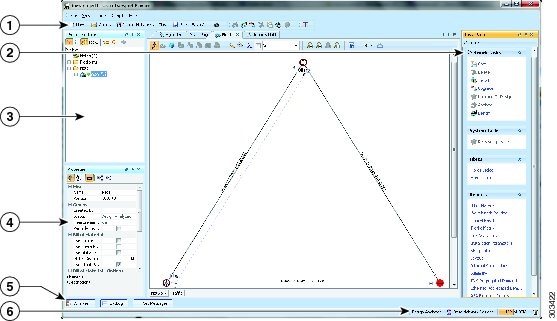
1 |
Tool Bar |
4 |
Properties Pane |
2 |
Tasks Pane |
5 |
Analyzer Pane |
3 |
Project Explorer Pane |
6 |
Status Bar |
A.1.1 Menu and Toolbar Options
The Cisco Transport Planner window menu bar and toolbar provide primary Cisco Transport Planner functions. Table A-1 shows the actions that are available from the menu and toolbar.
|
|
|
|
|
|---|---|---|---|
File |
New |

|
Creates a new Cisco Transport Planner project. See the "Creating a Project" section. |
Open |

|
Opens an existing Cisco Transport Planner project. See the "Opening a Project" section. |
|
Import Network |

|
Imports node parameters from a network. |
|
Close |

|
Closes the current project without closing the Cisco Transport Planner session. If you have not saved the current project, Cisco Transport Planner will prompt you to save before closing. See the "Closing a Project" section. |
|
Save |

|
Saves the current project. See the "Closing a Project" section. |
|
Save As |

|
Allows you to save the current project with a new file name. See the "Saving a Project" section. |
|
Clear History |
— |
Clears the file history from Cisco Transport Planner. Cisco Transport Planner maintains a list of the last ten open projects in the File menu. |
|
Exit |
— |
Exits the Cisco Transport Planner software. |
|
View |
My Default Layout |
— |
Changes the Cisco Transport Planner display to the user default layout. Cisco Transport Planner allows you to define the default value for Platform Options, Project Options, and General Options. The defined value are used as default for each new created project. See the "Setting Cisco Transport Planner Options" section. |
Default Layout |
— |
Returns the Cisco Transport Planner display to the system default layout. |
|
Tasks Pane |
— |
Displays the commands available for the selected entity (network, site, duct, etc.). |
|
Project Explorer |
— |
Displays the Project Explorer pane, which includes folders for project notes, networks, sites, fibers, traffic demand groups, subnets, maintenance centers, restricted equipment list, and reports. Clicking the plus (+) sign by each folder expands the folder. Clicking the minus (-) sign by each folder hides the folder. contents. You can also right-click a folder and choose Expand from the shortcut menu to show folder contents. The default location of the Project Explorer pane is the upper left section of the Cisco Transport Planner window. |
|
Properties |
— |
Displays the Properties pane, which shows parameter settings for the selected entity in the Project Explorer pane, Mgmt Tree tab, or NtVw Net# tab. The default location of the Properties pane is the lower left section of the Cisco Transport Planner window. |
|
Analyzer Messages |
— |
Displays the Analyzer Messages pane at the bottom of the Cisco Transport Planner window. The Analyzer Messages pane displays any error messages that occur during network analysis. |
|
A2A Finalized Circuits |
— |
Displays Any-to-Any Finalization report at the bottom of the Cisco Transport Planner window. The Any-to-Any Finalization report pane displays the demands that are finalized in the network. |
|
Tools |
Options |
— |
Opens the Options Explorer dialog box, where you can change the user default settings. See the "Setting Cisco Transport Planner Options" section. |
DB Parts Mgmt |
— |
Opens the PartsTreePanel dialog box, where you can view the list of available parts for each release. See the "Setting the Default Project Values" section. |
|
Price List Mgmt |
— |
Opens the Price Manager dialog box, where you can view maintenance contracts and add price databases. See the "Managing the Price List" section. |
|
Export |
— |
Opens the Export dialog box, which allows you to export user options, price lists, maintenance contracts, and parts database files. See the "Exporting User Options, Price Lists or Alien Definitions" section. |
|
Import |
— |
Opens the Import dialog box, which allows you to import user options, price lists, maintenance contracts, and parts database files. See the "Importing User Options, Price Lists or Alien Definitions" section. |
|
Import from Sherpa |
— |
Opens the Import dialog box, which allows you to import Layer 2 network designs using the Cisco Carrier Packet Transport system. |
|
Delete Cache |
— |
Deletes the CTP cache on restart. |
|
Help |
Manual |
— |
Opens the Cisco Transport Planner online help. |
Tips Of The Day |
— |
Opens the Tip of the Day dialog box, which provides helpful hints about using Cisco Transport Planner. Click the Next button to view the next tip and the Back button to view a previous tip. Check Show Tips on Startup to display the Tip of the Day dialog box when you launch Cisco Transport Planner. |
|
About |
— |
Displays Cisco Transport Planner version information. |
|
Network Toolbar |
|||
— |
Create a new site |

|
Opens the Site Creation wizard when you click this icon and then click in the Cisco Transport Planner window. See the "Adding Sites" section. |
— |
Create a new duct |

|
Allows you to create a new duct between sites. See the "Adding Fiber Spans" section. |
— |
Create a new P2P demand |

|
Opens the Point to Point Demand Creation wizard when you click this icon and then click two sites. See the "Creating a Point-to-Point Demand" section. |
— |
Create a new P-ring demand |

|
Opens the P-Ring Creation wizard. See the "Creating a Protected Ring Demand" section. |
— |
Finalize Any-to-Any traffic |

|
Opens Finalize Any-to-Any Traffic window. |
— |
Toggle the filter for Any-to-Any finalized traffic |

|
Displays the Any-to-Any demands that are finalized in the network. |
— |
Create a new TDM Aggregated demand |

|
Opens a TDM creation wizard. See the Creating TDM Aggregated Demands |
— |
Create a new Ethernet Aggregated demand |

|
Opens a Ethernet creation wizard. See the Creating Ethernet Aggregated Demands |
— |
Set various GUI options |

|
Displays the CTP GUI Options dialog box where the wavelength options can be set. The wavelength information can be displayed in nm, as a channel number or both. |
— |
Hide/show Network Details |

|
Hides or displays duct information (duct name, EOL), amplifier forcing, and circuits on the network map in the Network tab. |
— |
Wavelength usage information |

|
Hides or displays wavelength usage percentage in color on the network map in the Network tab. – – |
— |
Zoom in |

|
Zooms in on the NtVw Net# tab. |
— |
Zoom out |

|
Zoom out from the NtVw Net# tab. |
— |
Normal viewing |

|
Returns the NtVw Net# tab to normal viewing (1:1). |
— |
Fit to window |

|
Resizes the view so that all sites fit inside the NtVw Net# tab window. |
— |
Save network view image |

|
Saves a JPEG of the network design. See the "Creating a JPEG of the Network Design" section. |
— |
Analyze Network |

|
Analyzes the selected network. See the "Analyzing the Network" section. |
— |
Enter design mode |

|
Puts the selected Design-Analyzed network back into the design mode for further changes. See the "Analyzing the Network" section. |
— |
Put current network in upgrade mode |

|
Creates a copy of the selected Design-Analyzed network in the Upgrade state. See the "Creating an Upgrade Network" section. |
— |
Delete current network |

|
Deletes the selected network. See the "Deleting a Network" section. |
— |
Copy current network |

|
Copies the selected network. See the "Creating a Copy of the Network" section. |
— |
Put current network in install mode |

|
Creates a copy of the selected Design-Analyzed network in the Install state. See the "Creating a Network in the Install State" section. |
— |
Copy & Go back to Design Mode |

|
Copies the selected network in the Design state. See the "Creating a Copy of the Network in Design State" section. |
— |
Reports Diff |

|
Opens the Reports Diff dialog box, which allows you to create a report that shows the differences between networks. |
— |
Run the Garbage Collector |

|
Deletes unloaded networks from memory. |
A.1.2 Cisco Transport Planner Panes
Cisco Transport Planner provides four panes that help you manage a network design: Project Explorer, Properties, Analysis, and Tasks Pane.
A.1.2.1 Project Explorer Pane
The Project Explorer pane provides a management tree for the entire project. Each network appears as a folder that contains the sites, fibers, traffic groups, subnets, maintenance centers, restricted equipment lists, and reports for that network. If you have made changes to a network design, that network folder and the changed item folder appear in blue italics in the pane.
By default, the Project Explorer pane is located in the upper-left section of the Cisco Transport Planner window. Table A-2 shows the actions that are available from the Project Explorer toolbar.


A.1.2.2 Properties Pane
The Properties pane shows all of the parameters set for a selected item (either in the Project Explorer pane, the Network Mgmt Tree tab, or the NtVw Net# tab). Many items are editable in the Properties pane. By default, the Properties pane is located in the lower-left section of the Cisco Transport Planner window.
Table A-3 shows the actions that are available from the Properties Pane toolbar.


A.1.2.3 Analyzer Pane
The Analyzer tab at the bottom of the Cisco Transport Planner window appears after you have analyzed a network design. Clicking the Analyzer tab opens the Analyzer pane. Table A-5 shows the actions that are available from the Analyzer pane.


A.1.2.4 Tasks Pane
The Tasks Pane lists the available commands and reports for a selected item. The commands change based on the selected item. For example, a selected site will have different commands available than a selected fiber span. By default, the Tasks Pane is located in the upper right section of the Cisco Transport Planner window. Table A-5 shows the actions that are available from the Tasks Pane toolbar.
A.1.3 Shortcuts
Cisco Transport Planner provides the following mouse shortcuts:
•![]() Double-clicking a network icon in the Network Mgmt Tree tab opens the NtVw Net# tab, which shows the sites for that network.
Double-clicking a network icon in the Network Mgmt Tree tab opens the NtVw Net# tab, which shows the sites for that network.
•![]() Right-clicking a report table column displays a shortcut menu that allows you to view or hide the columns in a report.
Right-clicking a report table column displays a shortcut menu that allows you to view or hide the columns in a report.
•![]() Right-clicking an item in the Network Mgmt Tree tab or NtVw Net# tabs opens a shortcut menu that allows you to choose actions to perform on the selected item. The shortcut menu options differ based on the item selected and the network state. (Many commands are not available until a network is analyzed.) Table A-6 lists the shortcut menu actions that are available for each item.
Right-clicking an item in the Network Mgmt Tree tab or NtVw Net# tabs opens a shortcut menu that allows you to choose actions to perform on the selected item. The shortcut menu options differ based on the item selected and the network state. (Many commands are not available until a network is analyzed.) Table A-6 lists the shortcut menu actions that are available for each item.
•![]() Right-clicking on multiple items in the Project Explorer pane opens a shortcut menu that allows you to choose actions to perform on multiple items. The shortcut menu options are Delete, Unlock, Unlock Pay As You Grow Bundles, and Insert Site. The Unlock Pay As You Grow Bundles option is available only for sites and the Insert Site option is available only for ducts.
Right-clicking on multiple items in the Project Explorer pane opens a shortcut menu that allows you to choose actions to perform on multiple items. The shortcut menu options are Delete, Unlock, Unlock Pay As You Grow Bundles, and Insert Site. The Unlock Pay As You Grow Bundles option is available only for sites and the Insert Site option is available only for ducts.
|
|
|
|---|---|
Networks in the following states: Design, Install, and Upgrade |
• • |
Networks in the following states: Design, Install, and Upgrade |
• • • • • |
Analyzed networks |
• • • • • • • • • • • • |
Analyzed networks |
• – – Arrange Sites—Allows you to rearrange sites in the Cisco Transport Planner window. See the "Arranging Sites" section |
Sites |
• • • • If the network is analyzed, the following actions are also available: • • • • • • – – • • |
Sites |
• • • |
Fiber spans |
• If the network is analyzed, the Unlock command is also available. See the "Unlocking Parameters in the Network Design" section. |
Traffic demands |
• • • • If the network is analyzed, the Unlock command is also available. See the "Unlocking Parameters in the Network Design" section. |
A.2 Site Icons
A site icon indicates the functionality of site. Table A-7 lists the site icons.


A.3 Demand Editor Icons


 Feedback