- Preface
- Introduction
- Creating and Analyzing Networks
- Viewing Network Reports
- Editing a Project
- Modeled Network Examples
- GUI Information and Shortcuts
- Card Types
- System Messages
- Third-Party DWDM Wavelength Interface Model
- Configuring CTP to Run on a Server
- Pay As You Grow Licensing
- OSMINE Layout Rules
Modeled Network Examples
This chapter provides examples of typical optical networks you can model using the Cisco Transport Planner.
5.1 Supported Cisco Transport Planner Topologies
The Cisco Transport Planner supports the following topologies:
- Linear (Single-Span Topology or Multispan Topology)
- Ring (Hubbed Ring Topology or Closed Ring Topology)
- Mesh Topology
An example of each topology is given in this chapter.
5.1.1 Linear Topologies
In a linear topology, the nodes are arranged in a line and are connected to two other adjacent nodes. However, the first and last node are not connected. There are two types of linear topologies, single-span and multispan.
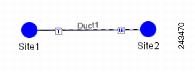
5.1.1.1 Single-Span Topology
Figure 5-1 shows an example of a single-span topology. This topology is characterized by a single span link. It can support only two terminal sites (full terminal or flexible channel-count terminal) without any intermediate line amplifier or optical add/drop multiplexing (OADM) sites.
Figure 5-1 Single-Span Topology Example
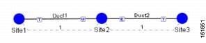
5.1.1.2 Multispan Topology
Figure 5-2 shows an example of a multispan topology. This configuration is characterized by the presence of two terminal sites (full terminal or flexible channel-count terminal) with intermediate OADM or line amplifier nodes. In a multispan configuration, specific wavelengths are terminated at different points in the span and only unprotected traffic can be provisioned.
Figure 5-2 Multispan Topology Example
5.1.2 Ring Topology
In a ring topology, each node is connected to exactly two other nodes, forming a circular configuration. It requires at least three nodes to form a ring. There are two types of ring topologies—closed ring and hubbed ring.
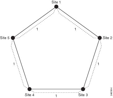
5.1.2.1 Closed Ring Topology
Figure 5-3 shows an example of a closed ring configuration. Here the traffic flows in a circular manner across the network.
Figure 5-3 Closed Ring Topology Example
5.1.2.2 Hubbed Ring Topology
Figure 5-4 shows an example of a hubbed ring topology, also knows as an open ring. In this configuration, at least one of the sites must be a hub site, where all channels are terminated. At the hub site, no traffic is expressed from one side to another, hence forming a break in the ring.
Figure 5-4 Hubbed Ring Topology Example
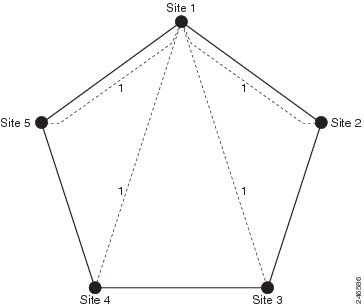
5.1.3 Mesh Topology
Figure 5-5 shows an example of a mesh topology where each node is connected to one or more nodes. This configuration provides maximum redundancy to the network.
Figure 5-5 Mesh Ring Topology Example

 Feedback