Installing the Cisco NCS 2002 Door and Other Modules

This chapter describes how to install the NCS 2015 door and other modules.

The sections are:

Front Door

The front door of the NCS 2002 provides access to the shelf and air-filter.

There are two types of front doors that act as protective panels—standard door and deep-front panel. The deep-front panel provides additional space in front of the shelf to accommodate cables that do not fit inside the standard door. The deep-front panel provides more space for fiber bend radius and to manage the line card connections. The deep-front panel does not have a hinge and cannot be rotated like the standard door.

If a standard front door was ordered, the NCS 2002 is shipped with a preinstalled standard door. If a deep-front panel was ordered, it is shipped in a separate package.

You can remove the door to provide unrestricted access to the front of the shelf.

An erasable label is pasted on the inside of the front door. You can use the label to record slot and port assignments, card types, node ID, rack ID, and serial number of the NCS 2002 shelf.

The following figure shows the erasable label on the NCS 2002 shelf.

Figure 1. NCS 2002 Front-Door Erasable Label
NCS 2002 Front-Door Erasable Label

The laser warning label is placed on top of the chassis (see the figure above).

The following figure shows the label placed on the NCS 2002 surface, inside the shelf close to the door hinges, below Slot 1.

Figure 2. NCS 2002 Label
NCS 2002 Label

NTP-L29 Installing the Standard Door of the NCS 2002 Shelf

Purpose

This procedure installs the standard door of the NCS 2002

Tools/Equipment

#2 Phillips Dynamometric screwdriver

Prerequisite Procedures

Required/As Needed

As needed

Onsite/Remote

Onsite

Security Level

None

Procedure


Step 1

Pull the hinge pins on the standard door in the opposite directions (see the figure below).

Figure 3. Installing the Standard Door
Installing the Standard Door

Step 2

Align the standard door hinges with the chassis hinges.

Step 3

Release the hinge pins.

Note

 
Reinstall the door after installing all the other modules.

Step 4

Place the ground strap cable (see the figure below) on the door and the chassis and tighten the nuts.

Figure 4. Ground Strap Cable—Standard Door
Ground Strap Cable Standard Door

Step 5

Tighten the door screws to a torque value of 6.5 in-lb (0.75 N-m) to close the standard door as shown in the figure below.

Figure 5. Close the Standard Door of NCS 2002 Shelf
Close the Standard Door of NCS 2002 Shelf

Stop. You have completed this procedure.


NTP-L30 Opening and Removing the Standard Door of the NCS 2002 Shelf

Purpose

This procedure opens and removes the standard door of the NCS 2002.

Tools/Equipment

#2 Phillips Dynamometric screwdriver

Prerequisite Procedures

Required/As Needed

Required

Onsite/Remote

Onsite

Security Level

None

Procedure


Step 1

Complete the DLP-L45 Opening the Standard Door of the NCS 2002 Shelf.

Step 2

Complete the DLP-L46 Removing the Standard Door of the NCS 2002 Shelf.

Stop. You have completed this procedure.


DLP-L45 Opening the Standard Door of the NCS 2002 Shelf

Purpose

This task opens the standard door of the NCS 2002 system.

Tools/Equipment

#2 Phillips Dynamometric screwdriver

Prerequisite Procedures

Required/As Needed

Required

Onsite/Remote

Onsite

Security Level

None


Caution


The NCS 2002 shelf has an ESD plug input and is shipped with an ESD wrist strap. The ESD plug input is located on the outside of the shelf on the right side. It is labeled “ESD” on the top and bottom. Always wear an ESD wrist strap and connect the strap to the ESD plug when working on the NCS 2002. For detailed instructions on how to wear the ESD wristband, refer to the Electrostatic Discharge and Grounding Guide for Cisco NCS 2000 Series .


Procedure


Step 1

Loosen the standard door screws (see the figure below).

Step 2

Push the latches in the opposite direction as shown in the figure below.

Figure 6. Opening the Standard Door
Opening the Standard Door

Step 3

Swing the door open (see the figure below).

Figure 7. Cisco NCS 2002 Standard Door—Opened
Cisco NCS 2002 Standard Door Opened

Step 4

Return to your originating procedure (NTP).


DLP-L46 Removing the Standard Door of the NCS 2002 Shelf

Purpose

This task removes the standard door of the NCS 2002 system.

Tools/Equipment

#2 Phillips Dynamometric screwdriver

Prerequisite Procedures

Required/As Needed

As needed

Onsite/Remote

Onsite

Security Level

None

Procedure


Step 1

Unscrew the nut holding the ground cable to the shelf. Remove the nut.

Step 2

Remove the ground cable from the shelf (see the figure below).

Figure 8. Removing the Standard Door
Removing the Standard Door

Step 3

Pull the hinge pins holding the door to the chassis, in the opposite direction (see the figure below).

Step 4

Remove the door from its hinges (see the figure below).

Figure 9. Removing the Standard Door
Removing the Standard Door

Step 5

Return to your originating procedure (NTP).


NTP-L40 Installing the Deep-Front Panel of the NCS 2002 Shelf

Purpose

This procedure installs the deep-front panel of the NCS 2002 shelf.

Tools/Equipment

#2 Phillips Dynamometric screwdriver

Prerequisite Procedures

Required/As Needed

As needed

Onsite/Remote

Onsite

Security Level

None


Note


Use the deep front panel when ONS-SC+-10G-C pluggables are installed on a NCS 2002 shelf.

Procedure


Step 1

Connect the ground strap cable:

  1. Loosen the ground nut from the shelf (see the figure below).

  2. Insert the lug of the ground strap cable and tighten the nut on the shelf to a torque value of 11.5 in-lb (1.3 N-m) (see the figure below).

  3. Route the other end of the ground strap cable outside the shelf at an angle of 180 degrees towards the left direction.

    Figure 10. Inserting the Lug to the Shelf
    Inserting the Lug to the Shelf

Step 2

Loosen the deep-front panel screws and slide them outwards using the plastic tabs .

Figure 11. Align the Deep-Front Panel and Shelf

Step 3

Place the deep-front panel close to the shelf so that the shelf notches and the deep-front panel retention features are in line (see the figure below).

Figure 12. Deep-Front Panel and Shelf in line
Deep-Front Panel and Shelf in line

Step 4

Align the deep-front panel with the shelf by performing the following sub-steps at the same time:

  1. Align the right and left retention features of the deep-front panel with the right and left notches present on the top of the shelf (see the figure above).

  2. Align the deep-front panel pins present at the bottom of the panel with the shelf hinges (see the figure below).

    Figure 13. Align the Deep-Front Panel and Shelf
    Align the Deep-Front Panel and Shelf

    The figure below shows the deep-front panel aligned with the shelf.

    Figure 14. Engage the Deep-Front Panel and Shelf
    Engage the Deep-Front Panel and Shelf

Step 5

Slide the deep-front panel screws inwards using the plastic tabs to engage the retention features and the pins with the shelf notches and hinges (see the figure below). Verify the engagement by gently applying the pressure to the panel outwards.

Figure 15. Engage the Deep-Front Panel and Shelf
Engage the Deep-Front Panel and Shelf

Step 6

Lock the deep-front panel by tightening the screws to a torque value of 6.5 in-lb (0.75 N-m).

Step 7

Connect the other end of the ground strap cable to the ground point present on the deep-front panel exterior.

Figure 16. Connecting the Ground Strap Cable
Connecting the Ground Strap Cable

Stop. You have completed this procedure.


NTP-G331 Removing the Deep-Front Panel of the NCS 2002 Shelf

Purpose

This procedure removes the deep-front panel of the NCS 2002 system.

Tools/Equipment

#2 Phillips Dynamometric screwdriver

Prerequisite Procedures

Required/As Needed

Required

Onsite/Remote

Onsite

Security Level

None

Procedure


Step 1

Remove the end of the ground strap cable that is connected to the exterior of the deep-front panel (see the figure below).

Figure 17. Remove the end of the ground strap cable
Remove the end of the ground strap cable

Step 2

Loosen the panel screws to open the deep-front panel.

Step 3

Move the deep-front panel screws in the direction as shown in the figure below to disengage the retention features and the pins from the shelf notches and hinges. (see the figure below).

Figure 18. Move the deep-front panel to disengage

Step 4

Move the deep-front panel away from the shelf (see the figure below).

Figure 19. Move the deep-front panel away
Move the deep-front panel away

Caution


The deep-front panel does not have a hinge and cannot be rotated like a standard door. Rotating the deep front panel can damage the deep-front panel, shelf hinges, other devices and cables placed below the NCS 2002 shelf.

Step 5

Remove the ground strap cable from the shelf (see the figure below):

Figure 20. Remove the ground strap cable
Remove the ground strap cable
  1. Loosen the ground nut on the shelf.

  2. Remove the lug and tighten the nut on the shelf to a torque value of 11.5 in-lb (1.3 N-m).

    Stop. You have completed this procedure.


Power Modules

The NCS 2002 system contains the following pluggable power modules:

  • AC power module
  • DC power module

In addition to supplying power to the NCS 2002 shelf, the power modules support the following connections:

  • LAN Connection—An Ethernet port (RJ-45) that supports the element manager system (EMS) connection. The RJ-45 port is used to connect the EMS or the craft interface terminal to access the NCS 2002 shelf.
  • Passive Unit Inventory Interfaces (USB port)—The passive unit inventory interfaces are used to retrieve inventory information from passive devices such as, fiber trays, FBG DCU, patch panels, passive muxponder and demuxponder and so on. The inventory details are displayed in the Inventory tab in CTC.
  • Timing Connections—The BITS-IN port receives input from third party external sources called SSU (Synchronization Supply Unit) to synchronize the timing of the NCS 2002 shelf. The BITS-OUT port provides output to external devices (other Cisco or third party shelves) to synchronize the timing signals with the NCS 2006 shelf.

The NCS 2002 shelf has a BITS-IN and BITS-OUT port on the power module. The BITS-IN and BITS-OUT connections are supported by:

    • Wire-wrap pins and mini-BNC connectors on the AC power module.
    • Mini-BNC connectors on the ETSI DC power module.
    • Wire-wrap pins on the ANSI DC power module.

Note


For timing connection, use 100-ohm shielded BITS clock cable pair #22 or #24 AWG (0.51 mm² [0.020 inch] or 0.64 mm² [0.0252 inch]) twisted-pair T1-type.

Note


Refer to Telcordia SR-NWT-002224 for rules about provisioning timing references.

AC Power Module

The AC power module converts the AC input current to DC output current.

Each AC power module has:

  • One AC single phase three poles (line L, Neutral N, and Protective Earth PE) input connector
  • One RJ-45 port for EMS connection
  • One USB port to support passive unit remote inventory connection
  • Two BITs connections (IN and OUT) for network synchronization supported by mini BNC
  • Two BITs connections (IN and OUT) for network synchronization supported by four wire-wrap pins

The AC power module has a single dual-color (red and green) LED on the faceplate. When the AC power line is not connected, the LED is OFF. Green LED indicates that the AC power line is connected and the power module is functioning properly. Red LED indicates that the AC power line is connected but an alarm is present due to secondary (48 V) fuse break. The shelf controller card controls the conditions that result in triggering the LED. The LED can be overwritten by the shelf controller card (TNC, TNCE, TSC, or TSCE) in all the three states (OFF/red/green). The AC power module supports the lamp test procedure and the LED changes its color or state. The fans in the NCS 2002 shelf cool the AC module and guarantee proper operation across the complete operating temperature or output power range.

DC Power Module

The NCS 2002 system can be powered by redundant DC power lines, however a single power line can power the entire NCS 2002 system. The DC power module draws the power from the batteries to turn on the NCS 2002.

Each ETSI DC power module has:

  • Two input battery connectors (two poles): -48V, RET for power terminals A and B.
  • One RJ-45 port for EMS connection
  • One USB port to support passive unit remote inventory connection
  • Two BITS connections (IN and OUT) for network synchronization that is supported by mini BNC

Each ANSI DC power module has:

  • Two terminal block connectors with -48V, RET for power terminals A and B
  • One RJ-45 port for EMS connection
  • One USB port to support passive unit remote inventory connection
  • Two BITS connections (IN and OUT) for network synchronization supported by four wire-wrap pins

The DC power module has a single dual-color (red and green) LED on the faceplate. When the battery is not connected, the LED is OFF. Green LED indicates that the battery is connected and the power module functions properly. Red LED indicates that the battery is connected but an alarm is present due to secondary fuse break (48 V). The DC power module does not support the lamp test procedure.

Modular DC Power Module

Table 1. Feature History

Feature Name

Release Information

Feature Description

New Modular DC Power Module on NCS 2002 Chassis

Cisco NCS 2000 Release 11.13

The design of the DC Power module is enhanced to make the power system modular. The modular units comprise a primary frame and two replaceable DC PSUs (available for both ETSI and ANSI variants), each with unique PIDs. The PSUs are field replaceable and provide redundancy to the power system.

The modular Dc Power module has three main components, one primary frame and two field replaceable DC PSUs (PSUA and PSUB). There are two variants of the PSUs, for ETSI and ANSI connectors. The DC Frame is common for both variants of the PSUs.

  • Main frame (PID: NCS2002-PSU-DC)—Includes two input slots to insert the PSUs, One RJ-45 port for EMS connection, One USB port to support passive unit remote inventory connection, two BITS connections (IN and OUT) for network synchronization.

  • PSUs—Field Replaceable Units (FRU) that can be inserted into the slots of the Main frame. The PSU has

    • The ETSI variant (PID: NCS2002-DC2-E) has two input battery connectors (two poles): -48V, RET for power terminals A and B.

    • The ANSI variant (PID: NCS2002-DC2-PSU-NA) has two terminal block connectors with -48V, RET for power terminals A and B.

In this modular DC power module, the input connector, DC filter and fuses for each battery are separated into two independent and field replaceable PSUs. In this case, if there is a failure on the protection block of one battery, it can be replaced without interrupting the functioning of the chassis.

Figure 21. Front View of the DC Frame
Figure 22. Perspective View of the DC Frame
Figure 23. Front View of the ETSI PSU
Figure 24. Perspective Views of ETSI PSU
Figure 25. Front View of the ANSI PSU
Figure 26. Perspective Views of the ANSI PSU

Note


When you plug out the PSU and plug it in again, the control card requires a minimum of five seconds to read the voltage. During this period, although the PSU is in place, the BAT-FAIL (Battery Fail) alarm will be raised followed by the ELWBATVG (Extreme Low Voltage) alarm. These alarms are raised after each plug out and plug in operation. However, these alarms will get cleared one after the other after few minutes.


NTP-L33 Installing the Power Module in the NCS 2002 Shelf

Purpose

This procedure installs the power module in the NCS 2002 system.

Tools/Equipment

#2 Phillips screwdriver

Prerequisite Procedures

Required/As Needed

Required

Onsite/Remote

Onsite

Security Level

None


Warning


The plug-socket combination must be accessible at all times because it serves as the main disconnecting device. Statement 1019


Note


During the system startup or fan-tray replacement, the inventory data of the fan-tray assembly and the power module is displayed in the Inventory tab of CTC after a delay of approximately 6 minutes.

Procedure


Step 1

Complete the necessary task as applicable:

Step 2

Complete the NTP-L35 Installing the Power and Ground to the NCS 2002 Shelf.

Stop. You have completed this procedure.


DLP-L47 Installing the AC Power Module in the NCS 2002 Shelf

Purpose

This procedure installs the AC power module in the NCS 2002 system.

Tools/Equipment

#2 Phillips screwdriver

Prerequisite Procedures

Required/As Needed

Required

Onsite/Remote

Onsite

Security Level

None


Caution


The AC power supply has Double Pole/Neutral Fusing.


Procedure


Step 1

Insert the AC power module in Slot A.

Figure 27. Installing the AC Power Module

Step 2

Plug the AC power module completely into the chassis.

Step 3

Tighten the screw to a torque value of 4 in-lb (0.45 N-m) to lock the power module in the chassis (see the figure below).

Figure 28. AC Power Module Installed in the NCS 2002 Shelf

Step 4

Return to your originating procedure.


DLP-L48 Installing the DC Power Module in the NCS 2002 Shelf

Purpose

This task installs the DC power module in the NCS 2002 system.

Tools/Equipment

#2 Phillips Dynamometric screwdriver

Prerequisite Procedures

Required/As Needed

Required

Onsite/Remote

Onsite

Security Level

None

Procedure


Step 1

Insert the DC power module in Slot A (see the figure below).

Figure 29. Installing the DC Power Module

Step 2

Plug the DC power module completely into the chassis.

Step 3

Tighten the screw to a torque value of 4 in-lb (0.45 N-m) to lock the power module in the chassis (see the figure below).

Figure 30. DC Power Modules Installed in the NCS 2002 Shelf

Step 4

Return to your originating procedure (NTP).


Installing the Modular DC Power Module

Purpose

This task installs the modular DC power module in the NCS 2002 system.

Tools/Equipment

Torque screwdriver or Flat screwdriver

Prerequisite Procedures

Connect the chassis to the office ground. For detailed instructions on how to ground the chassis, see the Electrostatic Discharge and Grounding Guide for Cisco NCS 2000 Series .

Required/As Needed

Required

Onsite/Remote

Onsite

Security Level

None

Procedure


Step 1

Insert the DC Frame in Slot A (see the figure below).

Figure 31. Inserting the DC Frame

1

Slot A

2

DC Frame

3

Captive screw

Step 2

Plug the DC frame completely into the chassis.

Step 3

Tighten the screw to a torque value of 4 in-lb (0.45 N-m) to lock the DC frame in the chassis (see the figure below).

Figure 32. DC Frame Installed in the ONS 15454 M2 Shelf

1

Captive screw

Step 4

Insert the PSU A and PSU B (ETSI or ANSI variant).

Figure 33. Inserting ANSI PSU in the DC Frame

1

PSU A

2

PSU B

3

Terminal block connectors

4

Captive screw

Figure 34. Inserting ETSI PSU in the DC Frame

1

PSU B

2

PSU A

3

D-sub connectors

4

Captive screws

Step 5

Tighten the screw to a torque value of 4 in-lb (0.45 N-m) to lock the PSUs into the DC frame (see the figures below).

Figure 35. ANSI PSU Installed into the DC Frame

1

PSU A

2

PSU B

3

Terminal Block Connectors

4

Captive screws

Figure 36. ETSI PSU Installed in the DC Frame

1

PSU A

2

PSU B

3

D-sub connectors

4

Captive screw

Step 6

Return to your originating procedure (NTP).


Fan-Tray Assembly

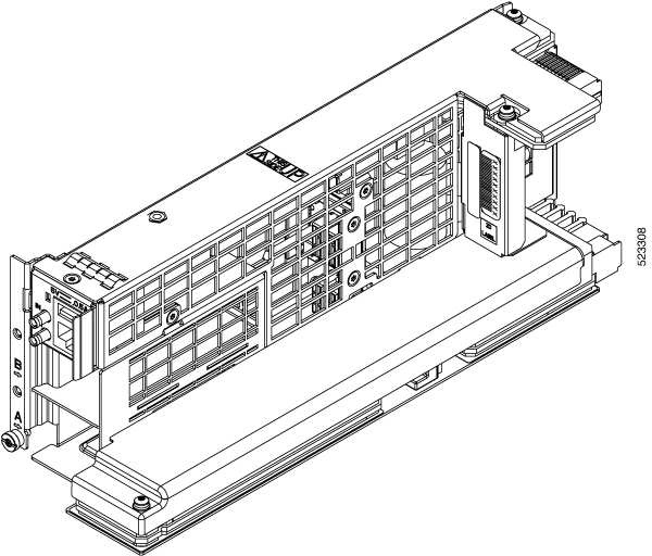
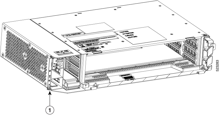
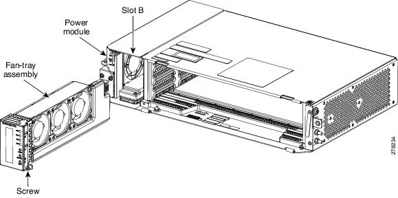
The fan-tray supported on the Cisco NCS 2002 shelf is FTA

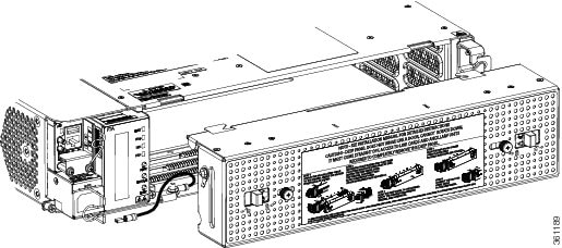
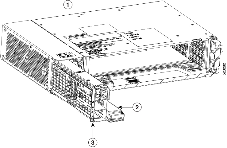
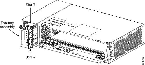
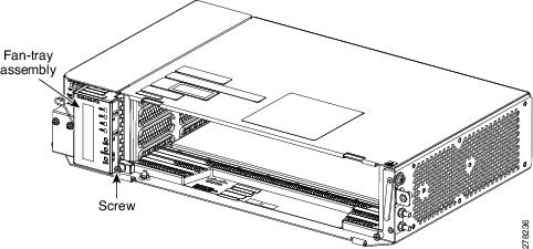
The fan-tray assembly is installed on the left side of the NCS 2002 shelf. The fan-tray assembly is removable and holds the fan-control circuitry and the fans for the NCS 2002 shelf.

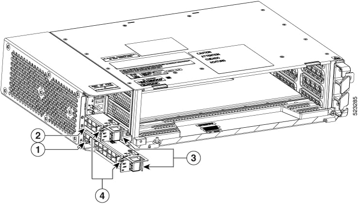
There are four LEDs on the fan-tray assembly:

  • Three alarm LEDs (CRIT, MAJ, and MIN) that indicate whether a critical, major, or minor alarm is present anywhere on the NCS 2002 shelf.
  • One fan fail LED that indicates fan failure.

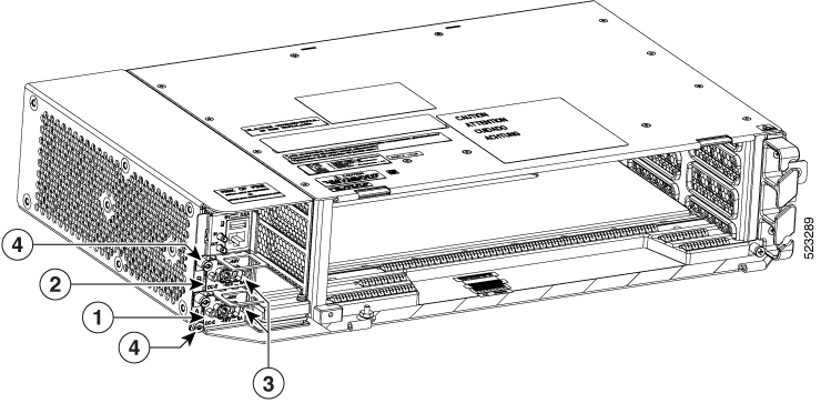
When the fan-tray assembly is not functioning and the power line is not connected, the LED is OFF. A red LED indicates an alarm in the fan-tray assembly. A green LED indicates that the fan-tray assembly is functioning, the power line is connected, and the power module is functioning properly, the LED is green. When the power line is connected and if there is no TNC, TNCE, TSC, or TSCE card installed in the NCS 2002 shelf, then the LED is OFF.

The shelf controller card controls the conditions that result in triggering the LEDs. The LED can be overwritten by the shelf controller card (TNC, TNCE, TSC, or TSCE) in all the three states (OFF/red/green). The fan-tray assembly supports the lamp test procedure.

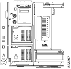
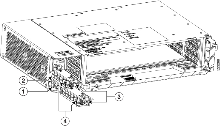
The fan-tray assembly has an LCD screen that provides slot and port-level information for all card slots, and the number of critical, major, and minor alarms. The shelf controller card (TSC, TSCE, TNC, or TNCE) drives the 16 X 2 character LCD screen. The LCD screen displays the shelf name, IP address, and software version that is currently used. The display contrast is automatically adjusted for clear view. The three accessible push buttons (SLOT, STATUS, and PORT) on the fan-tray assembly are used to set the slot and port level parameters.


Note


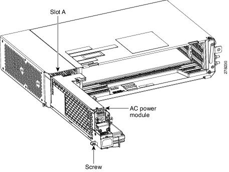
The fan-tray assembly should be installed only after installing the power module. During the system startup or fan-tray replacement, the inventory data of the fan-tray assembly and the power module is displayed in the Inventory tab of CTC after a delay of approximately 6 minutes.

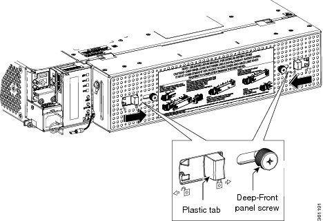
After you install the fan-tray, you should only access it if a fan failure occurs. To clean and replace the fan-tray assembly, see the “Maintain the Node” chapter in the Cisco NCS 2000 Series Network Configuration Guide .


Note


If the fan-tray assembly is removed from the shelf, wait for at least 5 seconds before plugging it back into the shelf. In the event the LCD display on the fan-tray assembly appears blank, remove the unit from the shelf, wait for at least 5 seconds and reinsert the unit into the shelf.

A back-up flash memory is fitted into the fan-tray assembly to support the database (DB) and image back-up in the single mode operation of the NCS 2002.
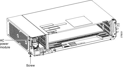
Fan Speed

Fan speed is controlled by the TNC, TNCE, TSC, or TSCE card temperature sensors. The sensors measure the input air temperature at the fan-tray assembly. Fan speed options are low, medium, and high. If the TNC, TNCE, TSC, or TSCE card fails, the fans automatically shift to high speed. The temperature measured by the TNC, TNCE, TSC, or TSCE sensors appears on the LCD screen.

Fan Failure

If one or more fans fail on the fan-tray assembly, replace the entire assembly. You cannot replace individual fans. The red Fan Fail LED on the front of the fan-tray illuminates when one or more fans fail. The red Fan Fail LED clears after you install a working fan-tray.

NTP-L35 Installing the Fan-Tray Assembly in the NCS 2002 Shelf

Purpose

This procedure installs the FTA or FTA2 fan-tray assembly in the NCS 2002 system.

Tools/Equipment

Small slot-head screwdriver

Prerequisite Procedures

Required/As Needed

Required

Onsite/Remote

Onsite

Security Level

None


Caution


Hazardous moving parts. Keep away from moving fan blades during fan tray replacement.


Caution


Do not operate an NCS 2002 shelf without an air filter. For information on the air filter, see Air Filter.


Caution


Do not force a fan-tray module into place. Doing so can damage either the connectors on the fan-tray or the connectors on the backpanel of the shelf, or both.


Note


Error messages appear on the TNC, TNCE, TSC, or TSCE card, the fan-tray LED, and in the Cisco Transport Controller (CTC) when the fan-tray module is removed from the shelf or when one fan is not working.

Note


During the system startup or fan-tray replacement, the inventory data of the fan-tray assembly and the power module is displayed in the Inventory tab of CTC after a delay of approximately 6 minutes.

Note


To install the fan-tray assembly, it is not necessary to move any of the fiber-routing facilities.

Procedure


Step 1

Insert the fan-tray assembly in Slot B of the NCS 2002 chassis (see the figure below).

Figure 37. Installing the Fan-Tray Assembly

Step 2

Push the fan-tray assembly such that the backplane connector is completely engaged (see the figure below).

Figure 38. Inserting the Fan-Tray Assembly in the NCS 2002 Chassis

Step 3

Tighten the screw to a torque value of 4 in-lb (0.45 N-m) to lock the unit (see the figure below).

Figure 39. Fan-Tray Assembly Installed in the NCS 2002 Shelf

Step 4

To verify that the tray has plugged into the assembly, check the fan-tray and listen to determine if the fans are running.

Note

 
If the fan-tray assembly is removed from the shelf, wait for at least 5 seconds before plugging it back into the shelf. In the event the LCD display on the fan-tray assembly appears blank, remove the unit from the shelf, wait for at least 5 seconds and reinsert the unit into the shelf.

Stop. You have completed this procedure.


Air Filter

The NCS 2002 contains a preinstalled disposable air filter (NCS2002-FTF) on the right side of the shelf.

The disposable filter is made up of a gray, open-cell, polyurethane foam that is specially coated to provide fire and fungi resistance. Spare filters should be kept in stock. Inspection of the air filter must be performed as specified in your local site practices.

First inspection of the air filter should be performed six months after the system installation. Air filters must be inspected every quarter after the initial six month inspection. If they are dirty or clogged with dust, they must be replaced with a new air filter.


Caution


Do not operate an NCS 2002 without the mandatory air filter.