- Preface
- Chapter 1, Shelf Assembly Hardware
- Chapter 2, Common Control Cards
- Chapter 3, Optical Service Channel Cards
- Chapter 4, Optical Amplifier Cards
- Chapter 5, Multiplexer and Demultiplexer Cards
- Chapter 6, Tunable Dispersion Compensating Units
- Chapter 7, PSM Card
- Chapter 8, Optical Add/Drop Cards
- Chapter 9, Reconfigurable Optical Add/Drop Cards
- Chapter 10, Transponder and Muxponder Cards
- Chapter 11, Node Reference
- Chapter 12, Network Reference
- Chapter 13, Optical Channel Circuits and Virtual Patchcords Reference
- Chapter 14, Cisco Transport Controller Operation
- Chapter 15, Security Reference
- Chapter 16, Timing Reference
- Chapter 17, Manage Network Connectivity
- Chapter 18, Alarm and TCA Monitoring and Management
- Chapter 19, Performance Monitoring
- Chapter 20, SNMP
- Appendix A, Hardware Specifications
- Appendix B, Administrative and Service States
- Appendix C, Pseudo Command Line Reference
- Appendix D, Connector Losses in Raman Link Configuration
- Appendix E, Network Element Defaults
- 10.1 Card Overview
- 10.2 Safety Labels
- 10.2.1 Class 1 Laser Product Cards
- 10.2.1.1 Class 1 Laser Product Label
- 10.2.1.2 Hazard Level 1 Label
- 10.2.1.3 Laser Source Connector Label
- 10.2.1.4 FDA Statement Label
- 10.2.1.5 Shock Hazard Label
- 10.2.2 Class 1M Laser Product Cards
- 10.2.2.1 Class 1M Laser Product Statement
- 10.2.2.2 Hazard Level 1M Label
- 10.2.2.3 Laser Source Connector Label
- 10.2.2.4 FDA Statement Label
- 10.2.2.5 Shock Hazard Label
- 10.3 TXP_MR_10G Card
- 10.4 TXP_MR_10E Card
- 10.4.1 Key Features
- 10.4.2 Faceplate and Block Diagram
- 10.4.3 Client Interface
- 10.4.4 DWDM Trunk Interface
- 10.4.5 Enhanced FEC (E-FEC) Feature
- 10.4.6 FEC and E-FEC Modes
- 10.4.7 Client-to-Trunk Mapping
- 10.4.8 Automatic Laser Shutdown
- 10.4.9 TXP_MR_10E Card-Level Indicators
- 10.4.10 TXP_MR_10E Port-Level Indicators
- 10.5 TXP_MR_10E_C and TXP_MR_10E_L Cards
- 10.5.1 Key Features
- 10.5.2 Faceplates and Block Diagram
- 10.5.3 Client Interface
- 10.5.4 DWDM Trunk Interface
- 10.5.5 Enhanced FEC (E-FEC) Feature
- 10.5.6 FEC and E-FEC Modes
- 10.5.7 Client-to-Trunk Mapping
- 10.5.8 Automatic Laser Shutdown
- 10.5.9 TXP_MR_10E_C and TXP_MR_10E_L Card-Level Indicators
- 10.5.10 TXP_MR_10E_C and TXP_MR_10E_L Port-Level Indicators
- 10.6 TXP_MR_2.5G and TXPP_MR_2.5G Cards
- 10.7 MXP_2.5G_10G Card
- 10.7.1 Timing Synchronization
- 10.7.2 Automatic Laser Shutdown
- 10.7.3 MXP_2.5G_10G Card-Level Indicators
- 10.7.3.1 MXP_2.5G_10G Port-Level Indicators
- 10.7.4 MXP_2.5G_10E Card
- 10.7.4.1 Key Features
- 10.7.5 Faceplate
- 10.7.6 Client Interfaces
- 10.7.6.1 DWDM Interface
- 10.7.7 Multiplexing Function
- 10.7.8 Timing Synchronization
- 10.7.9 Enhanced FEC ( E-FEC) Capability
- 10.7.10 FEC and E-FEC Modes
- 10.7.11 SONET/SDH Overhead Byte Processing
- 10.7.12 Client Interface Monitoring
- 10.7.13 Wavelength Identification
- 10.7.14 Automatic Laser Shutdown
- 10.7.15 Jitter
- 10.7.16 Lamp Test
- 10.7.17 Onboard Traffic Generation
- 10.7.18 MXP_2.5G_10E Card-Level Indicators
- 10.7.19 MXP_2.5G_10E Port-Level Indicators
- 10.8 MXP_2.5G_10E_C and MXP_2.5G_10E_L Cards
- 10.8.1 Key Features
- 10.8.2 Faceplate
- 10.8.3 Client Interfaces
- 10.8.4 DWDM Interface
- 10.8.5 Multiplexing Function
- 10.8.6 Timing Synchronization
- 10.8.7 Enhanced FEC ( E-FEC) Capability
- 10.8.8 FEC and E-FEC Modes
- 10.8.9 SONET/SDH Overhead Byte Processing
- 10.8.10 Client Interface Monitoring
- 10.8.11 Wavelength Identification
- 10.8.12 Automatic Laser Shutdown
- 10.8.13 Jitter
- 10.8.14 Lamp Test
- 10.8.15 Onboard Traffic Generation
- 10.8.16 MXP_2.5G_10E_C and MXP_2.5G_10E_L Card-Level Indicators
- 10.8.17 MXP_2.5G_10E and MXP_2.5G_10E_L Port-Level Indicators
- 10.9 MXP_MR_2.5G and MXPP_MR_2.5G Cards
- 10.9.1 Performance Monitoring
- 10.9.2 Distance Extension
- 10.9.3 Slot Compatibility
- 10.9.4 Interoperability with Cisco MDS Switches
- 10.9.5 Client and Trunk Ports
- 10.9.6 Faceplates
- 10.9.7 Block Diagram
- 10.9.8 Automatic Laser Shutdown
- 10.9.9 MXP_MR_2.5G and MXPP_MR_2.5G Card-Level Indicators
- 10.9.10 MXP_MR_2.5G and MX PP_MR_2.5G Port-Level Indicators
- 10.10 MXP_MR_10DME_C and MXP_MR_10DME_L Cards
- 10.11 GE_XP, 10GE_XP, GE_XPE, and 10GE_XPE Cards
- 10.11.1 Key F eatures
- 10.11.2 Faceplate and Block Diagram
- 10.11.3 Client Interface
- 10.11.4 GE_XP, 10GE_XP, GE_XPE, and 10GE_XPE Card-Level Indicators
- 10.11.5 GE_XP, 10GE_XP, GE_XPE, and 10GE_XPE Port-Level Indicators
- 10.11.6 DWDM Trunk Interface
- 10.11.7 Configuration Man agement
- 10.11.8 Security
- 10.11.9 Card Protection
- 10.11.9.1 1+1 Protection
- 10.11.9.2 Y-Cable Protection
- 10.11.9.3 Layer 2 Over DWDM Protection
- 10.11.10 IGMP Snooping
- 10.11.10.1 Fast-Leave Processing
- 10.11.10.2 Static Router Port Configuration
- 10.11.10.3 Report Suppression
- 10.11.10.4 IGMP Statistics and Counters
- 10.11.11 Multicast VLAN Registration
- 10.11.12 MAC Address Learning
- 10.11.13 MAC Address Retrieval
- 10.11.14 Link Integrity
- 10.11.15 Ingress CoS
- 10.12 ADM-10G Card
- 10.12.1 Key Features
- 10.12.2 GFP Interoperability
- 10.12.3 Faceplate
- 10.12.4 Port Configuration Rules
- 10.12.5 Client Interfaces
- 10.12.6 Interlink Interfaces
- 10.12.7 DWDM Trunk Interface
- 10.12.8 Configuration Management
- 10.12.9 Security
- 10.12.10 Protection
- 10.12.10.1 Circuit Protection Schemes
- 10.12.10.2 Port Protection Schemes
- 10.12.11 Circuit Provisioning
- 10.12.12 Automatic Laser Shutdown
- 10.12.13 ADM-10G Card-Level Indicators
- 10.12.14 ADM-10G Card Port-Level Indicators
- 10.13 OTU2_XP Card
- 10.13.1 Key Features
- 10.13.2 Faceplate and Block Diagram
- 10.13.3 OTU2_XP Card-Level Indicators
- 10.13.4 OTU2_XP Port-Level Indicators
- 10.13.5 OTU2_XP Card Interface
- 10.13.5.1 Client Interface
- 10.13.5.2 Trunk Interface
- 10.13.6 Configuration Management
- 10.13.7 OTU2_XP Card Configuration Rules
- 10.13.8 Security
- 10.13.9 Automatic Laser Shutdown
- 10.13.10 ODU Transparency
- 10.13.11 Protection
- 10.13.11.1 Y-Cable Protection
- 10.13.11.2 Splitter Protection
- 10.14 MLSE UT
- 10.15 TXP_MR_10EX_C Card
- 10.15.1 Key Features
- 10.15.2 Faceplate and Block Diagram
- 10.15.3 Client Interface
- 10.15.4 DWDM Trunk Interface
- 10.15.5 Enhanced FEC (E-FEC) Feature
- 10.15.6 FEC and E-FEC Modes
- 10.15.7 Client-to-Trunk Mapping
- 10.15.8 Automatic Laser Shutdown
- 10.15.9 TXP_MR_10EX_C Card-Level Indicators
- 10.15.10 TXP_MR_10EX_C Port-Level Indicators
- 10.16 MXP_2.5G_10EX_C card
- 10.16.1 Key Features
- 10.16.2 Faceplate
- 10.16.3 Client Interfaces
- 10.16.4 DWDM Interface
- 10.16.5 Multiplexing Function
- 10.16.6 Timing Synchronization
- 10.16.7 Enhanced FEC ( E-FEC) Capability
- 10.16.8 FEC and E-FEC Modes
- 10.16.9 SONET/SDH Overhead Byte Processing
- 10.16.10 Client Interface Monitoring
- 10.16.11 Wavelength Identification
- 10.16.12 Automatic Laser Shutdown
- 10.16.13 Jitter
- 10.16.14 Lamp Test
- 10.16.15 Onboard Traffic Generation
- 10.16.16 MXP_2.5G_10EX_C Card-Level Indicators
- 10.16.17 MXP_2.5G_10EX_C Port-Level Indicators
- 10.17 MXP_MR_10DMEX_C Card
- 10.18 Y-Cable and Splitter Protection
- 10.19 Far-End Laser Control
- 10.20 Jitter Considerations
- 10.21 Termination Modes
- 10.22 SFP and XFP Modules
Transponder and Muxponder Cards

Note![]() The terms "Unidirectional Path Switched Ring" and "UPSR" may appear in Cisco literature. These terms do not refer to using Cisco ONS 15xxx products in a unidirectional path switched ring configuration. Rather, these terms, as well as "Path Protected Mesh Network" and "PPMN," refer generally to Cisco's path protection feature, which may be used in any topological network configuration. Cisco does not recommend using its path protection feature in any particular topological network configuration.
The terms "Unidirectional Path Switched Ring" and "UPSR" may appear in Cisco literature. These terms do not refer to using Cisco ONS 15xxx products in a unidirectional path switched ring configuration. Rather, these terms, as well as "Path Protected Mesh Network" and "PPMN," refer generally to Cisco's path protection feature, which may be used in any topological network configuration. Cisco does not recommend using its path protection feature in any particular topological network configuration.
This chapter describes Cisco ONS 15454 transponder (TXP), muxponder (MXP), GE_XP, 10GE_XP, GE_XPE, 10GE_XPE, ADM-10G, and OTU2_XP cards, as well as their associated plug-in modules (Small Form-factor Pluggables [SFPs or XFPs]). For installation and card turn-up procedures, refer to the Cisco ONS 15454 DWDM Procedure Guide. For card safety and compliance information, refer to the Cisco Optical Transport Products Safety and Compliance Information document.
Note![]() Unless otherwise specified, “ONS 15454” refers to both ANSI and ETSI shelf assemblies.
Unless otherwise specified, “ONS 15454” refers to both ANSI and ETSI shelf assemblies.
- Card Overview
- Safety Labels
- TXP_MR_10G Card
- TXP_MR_10E Card
- TXP_MR_10E_C and TXP_MR_10E_L Cards
- TXP_MR_2.5G and TXPP_MR_2.5G Cards
- MXP_2.5G_10G Card
- MXP_2.5G_10E_C and MXP_2.5G_10E_L Cards
- MXP_MR_2.5G and MXPP_MR_2.5G Cards
- MXP_MR_10DME_C and MXP_MR_10DME_L Cards
- GE_XP, 10GE_XP, GE_XPE, and 10GE_XPE Cards
- ADM-10G Card
- OTU2_XP Card
- MLSE UT
- TXP_MR_10EX_C Card
- MXP_2.5G_10EX_C card
- MXP_MR_10DMEX_C Card
- Y-Cable and Splitter Protection
- Far-End Laser Control
- Jitter Considerations
- Termination Modes
- SFP and XFP Modules
Note![]() Cisco ONS 15454 DWDM supports IBM's 5G DDR (Double Data Rate) InfiniBand1 interfaces.
Cisco ONS 15454 DWDM supports IBM's 5G DDR (Double Data Rate) InfiniBand1 interfaces.
10.1 Card Overview
The card overview section lists the cards described in this chapter and provides compatibility information.
Note![]() Each card is marked with a symbol that corresponds to a slot (or slots) on the ONS 15454 shelf assembly. The cards are then installed into slots displaying the same symbols. See the “Card Slot Requirements” section for a list of slots and symbols.
Each card is marked with a symbol that corresponds to a slot (or slots) on the ONS 15454 shelf assembly. The cards are then installed into slots displaying the same symbols. See the “Card Slot Requirements” section for a list of slots and symbols.
The purpose of a TXP, MXP, GE_XP, 10GE_XP, GE_XPE, 10GE_XPE, ADM-10G, or OTU2_XP card is to convert the “gray” optical client interface signals into trunk signals that operate in the “colored” dense wavelength division multiplexing (DWDM) wavelength range. Client-facing gray optical signals generally operate at shorter wavelengths, whereas DWDM colored optical signals are in the longer wavelength range (for example, 1490 nm = violet; 1510 nm = blue; 1530 nm = green; 1550 nm = yellow; 1570 nm = orange; 1590 nm = red; 1610 nm = brown). Some of the newer client-facing SFPs, however, operate in the colored region. Transponding or muxponding is the process of converting the signals between the client and trunk wavelengths.
An MXP generally handles several client signals. It aggregates, or multiplexes, lower rate client signals together and sends them out over a higher rate trunk port. Likewise, it demultiplexes optical signals coming in on a trunk and sends them out to individual client ports. A TXP converts a single client signal to a single trunk signal and converts a single incoming trunk signal to a single client signal. GE_XP, 10GE_XP, GE_XPE, and 10GE_XPE cards can be provisioned as TXPs, as MXPs, or as Layer 2 switches.
All of the TXP and MXP cards perform optical to electrical to optical (OEO) conversion. As a result, they are not optically transparent cards. The reason for this is that the cards must operate on the signals passing through them, so it is necessary to do an OEO conversion.
On the other hand, the termination mode for all of the TXPs and MXPs, which is done at the electrical level, can be configured to be transparent. In this case, neither the Line nor the Section overhead is terminated. The cards can also be configured so that either Line or Section overhead can be terminated, or both can be terminated.
Note![]() The MXP_2.5G_10G card, by design, when configured in the transparent termination mode, actually does terminate some of the bytes. See Table 10-53 for details.
The MXP_2.5G_10G card, by design, when configured in the transparent termination mode, actually does terminate some of the bytes. See Table 10-53 for details.
10.1.1 Card Summary
Table 10-1 lists and summarizes the functions of each TXP, TXPP, MXP, MXPP, GE_XP, 10GE_XP, GE_XPE, 10GE_XPE, ADM-10G, and OTU2_XP card.
|
|
|
|
|---|---|---|
|
|
The TXP_MR_10G card has two sets of ports located on the faceplate. |
See the “TXP_MR_10G Card” section. |
|
|
The TXP_MR_10E card has two sets of ports located on the faceplate. |
See the “TXP_MR_10E Card” section. |
|
|
The TXP_MR_10E_C and TXP_MR_10E_L cards have two sets of ports located on the faceplate. |
|
|
|
The TXP_MR_2.5G card has two sets of ports located on the faceplate. |
|
|
|
The TXPP_MR_2.5G card has three sets of ports located on the faceplate. |
|
|
|
The MXP_2.5G_10G card has nine sets of ports located on the faceplate. |
See the “MXP_2.5G_10G Card” section. |
|
|
The MXP_2.5G_10E card has nine sets of ports located on the faceplate. |
See the “MXP_2.5G_10E Card” section. |
|
MXP_2.5G_10E_L |
The MXP_2.5G_10E_C and MXP_2.5G_10E_L cards have nine sets of ports located on the faceplate. |
|
|
|
The MXP_MR_2.5G card has nine sets of ports located on the faceplate. |
|
|
|
The MXPP_MR_2.5G card has ten sets of ports located on the faceplate. |
|
|
|
The MXP_MR_10DME_C and MXP_MR_10DME_L cards have eight sets of ports located on the faceplate. |
|
|
|
The GE_XP and GE_XPE cards have twenty Gigabit Ethernet client ports and two 10 Gigabit Ethernet trunk ports. |
See the “GE_XP, 10GE_XP, GE_XPE, and 10GE_XPE Cards” section. |
|
|
The 10GE_XP and 10GE_XPE cards have two 10 Gigabit Ethernet client ports and two 10 Gigabit Ethernet trunk ports. |
See the “GE_XP, 10GE_XP, GE_XPE, and 10GE_XPE Cards” section. |
|
|
The ADM-10G card has 19 sets of ports located on the faceplate. |
See the “ADM-10G Card” section. |
|
|
See the “OTU2_XP Card” section. |
|
|
|
The TXP_MR_10EX_C card has two sets of ports located on the faceplate. |
See the “TXP_MR_10EX_C Card” section. |
|
|
The MXP_2.5G_10EX_C card has nine sets of ports located on the faceplate. |
See the “MXP_2.5G_10EX_C card” section. |
|
|
The MXP_MR_10DMEX_C card has eight sets of ports located on the faceplate. |
See the “MXP_MR_10DMEX_C Card” section. |
10.1.2 Card Compatibility
Table 10-2 lists the Cisco Transport Controller (CTC) software compatibility for each TXP, TXPP, MXP, MXPP, GE_XP, 10GE_XP, GE_XPE, 10GE_XPE, ADM-10G, and OTU2_XP card.
|
|
|
|
|
|
|
|
|
|
|
|
|
|---|---|---|---|---|---|---|---|---|---|---|---|
10.2 Safety Labels
This section explains the significance of the safety labels attached to some of the cards. The faceplates of the cards are clearly labeled with warnings about the laser radiation levels. You must understand all warning labels before working on these cards.
10.2.1 Class 1 Laser Product Cards
The MXP_2.5G_10G, MXP_2.5G_10E, MXP_2.5G_10E_C, MXP_2.5G_10E_L, ADM-10G, GE_XP, 10GE_XP, GE_XPE, 10GE_XPE, and OTU2_XP cards have Class 1 lasers. The labels that appear on these cards are described in the following sections.
10.2.1.1 Class 1 Laser Product Label
The Class 1 Laser Product label is shown in Figure 10-1.
Figure 10-1 Class 1 Laser Product Label

Class 1 lasers are products whose irradiance does not exceed the Maximum Permissible Exposure (MPE) value. Therefore, for Class 1 laser products the output power is below the level at which it is believed eye damage will occur. Exposure to the beam of a Class 1 laser will not result in eye injury and can therefore be considered safe. However, some Class 1 laser products might contain laser systems of a higher Class but there are adequate engineering control measures to ensure that access to the beam is not reasonably likely. Anyone who dismantles a Class 1 laser product that contains a higher Class laser system is potentially at risk of exposure to a hazardous laser beam
10.2.1.2 Hazard Level 1 Label
The Hazard Level 1 label is shown in Figure 10-2. This label is displayed on the faceplate of the cards.
Figure 10-2 Hazard Level Label

The Hazard Level label warns users against exposure to laser radiation of Class 1 limits calculated in accordance with IEC60825-1 Ed.1.2.
10.2.1.3 Laser Source Connector Label
The Laser Source Connector label is shown in Figure 10-3.
Figure 10-3 Laser Source Connector Label

This label indicates that a laser source is present at the optical connector where the label has been placed.
10.2.1.4 FDA Statement Label
The FDA Statement labels are shown in Figure 10-4 and Figure 10-5. These labels show compliance to FDA standards and that the hazard level classification is in accordance with IEC60825-1 Am.2 or Ed.1.2.
Figure 10-4 FDA Statement Label
Figure 10-5 FDA Statement Label
10.2.1.5 Shock Hazard Label
The Shock Hazard label is shown in Figure 10-6.
Figure 10-6 Shock Hazard Label

This label alerts personnel to electrical hazard within the card. The potential of shock hazard exists when removing adjacent cards during maintenance, and touching exposed electrical circuitry on the card itself.
10.2.2 Class 1M Laser Product Cards
The TXP_MR_10G, TXP_MR_10E, TXP_MR_10E_C, TXP_MR_10E_L, TXP_MR_2.5G, TXPP_MR_2.5G, MXP_MR_2.5G, MXPP_MR_2.5G, MXP_MR_10DME_C, and MXP_MR_10DME_L cards have Class 1M lasers.
The labels that appear on these cards are described in the following subsections.
10.2.2.1 Class 1M Laser Product Statement
The Class 1M Laser Product statement is shown in Figure 10-7.
Figure 10-7 Class 1M Laser Product Statement

Class 1M lasers are products that produce either a highly divergent beam or a large diameter beam. Therefore, only a small part of the whole laser beam can enter the eye. However, these laser products can be harmful to the eye if the beam is viewed using magnifying optical instruments.
10.2.2.2 Hazard Level 1M Label
The Hazard Level 1M label is shown in Figure 10-8. This label is displayed on the faceplate of the cards.
Figure 10-8 Hazard Level Label

The Hazard Level label warns users against exposure to laser radiation of Class 1 limits calculated in accordance with IEC60825-1 Ed.1.2.
10.2.2.3 Laser Source Connector Label
The Laser Source Connector label is shown in Figure 10-9.
Figure 10-9 Laser Source Connector Label
This label indicates that a laser source is present at the optical connector where the label has been placed.
10.2.2.4 FDA Statement Label
The FDA Statement labels are shown in Figure 10-10 and Figure 10-11. These labels show compliance to FDA standards and that the hazard level classification is in accordance with IEC60825-1 Am.2 or Ed.1.2.
Figure 10-10 FDA Statement Label
Figure 10-11 FDA Statement Label
10.2.2.5 Shock Hazard Label
The Shock Hazard label is shown in Figure 10-12.
Figure 10-12 Shock Hazard Label
This label alerts personnel to electrical hazard within the card. The potential of shock hazard exists when removing adjacent cards during maintenance, and touching exposed electrical circuitry on the card itself.
10.3 TXP_MR_10G Card
The TXP_MR_10G processes one 10-Gbps signal (client side) into one 10-Gbps, 100-GHz DWDM signal (trunk side). It provides one 10-Gbps port per card that can be provisioned for an STM-64/OC-192 short reach (1310-nm) signal, compliant with ITU-T G.707, ITU-T G.709, ITU-T G.691, and Telcordia GR-253-CORE, or a 10GBASE-LR signal compliant with IEEE 802.3.
The TXP_MR_10G card is tunable over two neighboring wavelengths in the 1550-nm, ITU 100-GHz range. It is available in 16 different versions, each of which covers two wavelengths, for a total coverage of 32 different wavelengths in the 1550-nm range.
Note![]() ITU-T G.709 specifies a form of forward error correction (FEC) that uses a “wrapper” approach. The digital wrapper lets you transparently take in a signal on the client side, wrap a frame around it and restore it to its original form. FEC enables longer fiber links because errors caused by the optical signal degrading with distance are corrected.
ITU-T G.709 specifies a form of forward error correction (FEC) that uses a “wrapper” approach. The digital wrapper lets you transparently take in a signal on the client side, wrap a frame around it and restore it to its original form. FEC enables longer fiber links because errors caused by the optical signal degrading with distance are corrected.
The trunk port operates at 9.95328 Gbps (or 10.70923 Gbps with ITU-T G.709 Digital Wrapper/FEC) and at 10.3125 Gbps (or 11.095 Gbps with ITU-T G.709 Digital Wrapper/FEC) over unamplified distances up to 80 km (50 miles) with different types of fiber such as C-SMF or dispersion compensated fiber limited by loss and/or dispersion.

You can install TXP_MR_10G cards in Slots 1 to 6 and 12 to 17 and provision this card in a linear configuration. TXP_MR_10G cards cannot be provisioned as a bidirectional line switched ring (BLSR)/Multiplex Section - Shared Protection Ring (MS-SPRing), a path protection/single node control point (SNCP), or a regenerator. They can only be used in the middle of BLSR/MS-SPRing and 1+1 spans when the card is configured for transparent termination mode.
The TXP_MR_10G port features a 1550-nm laser for the trunk port and a 1310-nm laser for the for the client port and contains two transmit and receive connector pairs (labeled) on the card faceplate.
The MTU setting is used to display the OverSizePkts counters on the receiving trunk and client port interfaces. Traffic of frame sizes up to 65535 bytes pass without any packet drops, from the client port to the trunk port and vice versa irrespective of the MTU setting.
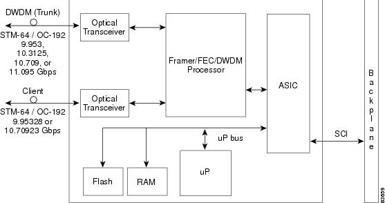
Figure 10-13 shows the TXP_MR_10G faceplate and block diagram.
Figure 10-13 TXP_MR_10G Faceplate and Block Diagram
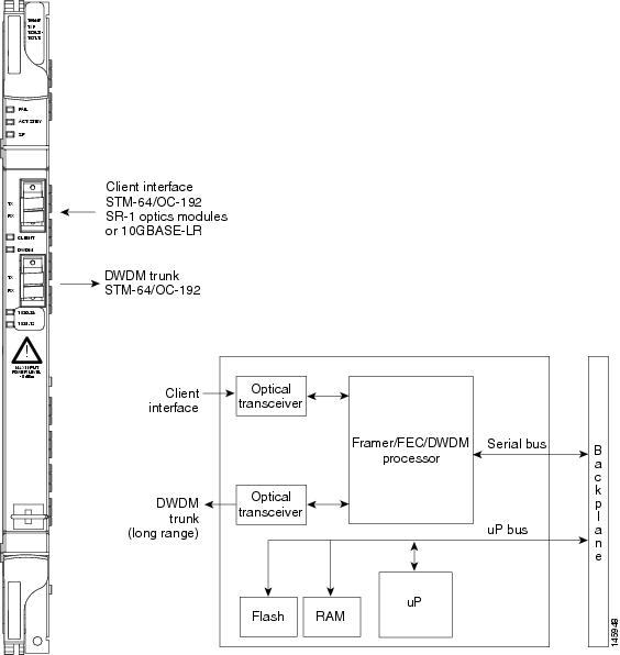
For information on safety labels for the card, see the “Class 1M Laser Product Cards” section.
10.3.1 Automatic Laser Shutdown
The Automatic Laser Shutdown (ALS) procedure is supported on both client and trunk interfaces. On the client interface, ALS is compliant with ITU-T G.664 (6/99). On the data application and trunk interface, the switch on and off pulse duration is greater than 60 seconds and is user-configurable. For details on ALS provisioning for the card, refer to the Cisco ONS 15454 DWDM Procedure Guide.
10.3.2 TXP_MR_10G Card-Level Indicators
Table 10-3 lists the three card-level LEDs on the TXP_MR_10G card.
10.3.3 TXP_MR_10G Port-Level Indicators
Table 10-4 lists the four port-level LEDs in the TXP_MR_10G card.
10.4 TXP_MR_10E Card
The TXP_MR_10E card is a multirate transponder for the ONS 15454 platform. The card is fully backward compatible with the TXP_MR_10G card. It processes one 10-Gbps signal (client side) into one 10-Gbps, 100-GHz DWDM signal (trunk side) that is tunable over four wavelength channels (spaced at 100 GHz on the ITU grid) in the C band and tunable over eight wavelength channels (spaced at 50 GHz on the ITU grid) in the L band. There are eight versions of the C-band card, with each version covering four wavelengths, for a total coverage of 32 wavelengths. There are five versions of the L-band card, with each version covering eight wavelengths, for a total coverage of 40 wavelengths.
You can install TXP_MR_10E cards in Slots 1 to 6 and 12 to 17 and provision the cards in a linear configuration, BLSR/MS-SPRing, path protection/SNCP, or a regenerator. The card can be used in the middle of BLSR/MS-SPRing or 1+1 spans when the card is configured for transparent termination mode.
The TXP_MR_10E card features a 1550-nm tunable laser (C band) or a 1580-nm tunable laser (L band) for the trunk port and a separately orderable ONS-XC-10G-S1 1310-nm or ONS-XC-10G-L2 1550-nm laser XFP module for the client port.
Note![]() When the ONS-XC-10G-L2 XFP is installed, the TXP_MR_10E card must be installed in Slots 6, 7, 12 or 13)
When the ONS-XC-10G-L2 XFP is installed, the TXP_MR_10E card must be installed in Slots 6, 7, 12 or 13)
On its faceplate, the TXP_MR_10E card contains two transmit and receive connector pairs, one for the trunk port and one for the client port. Each connector pair is labeled.
10.4.1 Key Features
The key features of the TXP_MR_10E card are:
- OC-192 to ITU-T G.709 OTU2 provisionable synchronous and asynchronous mapping
- The MTU setting is used to display the OverSizePkts counters on the receiving trunk and client port interfaces. Traffic of frame sizes up to 65535 bytes pass without any packet drops, from the client port to the trunk port and vice versa irrespective of the MTU setting.
10.4.2 Faceplate and Block Diagram
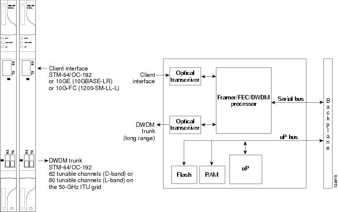
Figure 10-14 shows the TXP_MR_10E faceplate and block diagram.
Figure 10-14 TXP_MR_10E Faceplate and Block Diagram
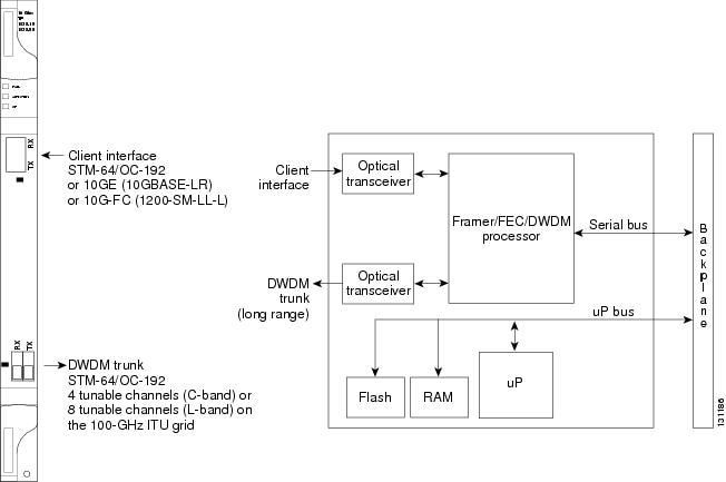
For information on safety labels for the card, see the “Class 1M Laser Product Cards” section.
10.4.3 Client Interface
The client interface is implemented with a separately orderable XFP module. The module is a tri-rate transceiver, providing a single port that can be configured in the field to support an OC-192 SR-1 (Telcordia GR-253-CORE) or STM-64 I-64.1 (ITU-T G.691) optical interface, as well as 10GE LAN PHY (10GBASE-LR), 10GE WAN PHY (10GBASE-LW), or 10G FC signals.
The client side XFP pluggable module supports LC connectors and is equipped with a 1310-nm laser.
10.4.4 DWDM Trunk Interface
On the trunk side, the TXP_MR_10E card provides a 10-Gbps STM-64/OC-192 interface. There are four tunable channels available in the 1550-nm band or eight tunable channels available in the 1580-nm band on the 50-GHz ITU grid for the DWDM interface. The TXP_MR_10E card provides 3R (retime, reshape, and regenerate) transponder functionality for this 10-Gbps trunk interface. Therefore, the card is suited for use in long-range amplified systems. The DWDM interface is complaint with ITU-T G.707, ITU-T G.709, and Telcordia GR-253-CORE standards.
The DWDM trunk port operates at a rate that is dependent on the input signal and the presence or absence of the ITU-T G.709 Digital Wrapper/FEC. The possible trunk rates are:
- OC192 (9.95328 Gbps)
- OTU2 (10.70923 Gbps)
- 10GE (10.3125 Gbps) or 10GE into OTU2 (ITU G.sup43 11.0957 Gbps)
- 10G FC (10.51875 Gbps) or 10G FC into OTU2 (nonstandard 11.31764 Gbps)
The maximum system reach in filterless applications without the use of optical amplification or regenerators is nominally rated at 23 dB over C-SMF fiber. This rating is not a product specification, but is given for informational purposes. It is subject to change.
10.4.5 Enhanced FEC (E-FEC) Feature
A key feature of the TXP_MR_10E is the availability to configure the forward error correction in three modes: NO FEC, FEC, and E-FEC. The output bit rate is always 10.7092 Gbps as defined in ITU-T G.709, but the error coding performance can be provisioned as follows:
- NO FEC—No forward error correction
- FEC—Standard ITU-T G.975 Reed-Solomon algorithm
- E-FEC—Standard ITU-T G.975.1 I.7 algorithm, which is a super FEC code
Note![]() The E-FEC of the ONS 15454 and Cisco ASR 9000 are not compatible.
The E-FEC of the ONS 15454 and Cisco ASR 9000 are not compatible.
10.4.6 FEC and E-FEC Modes
As client side traffic passes through the TXP_MR_10E card, it can be digitally wrapped using FEC mode, E-FEC mode, or no error correction at all. The FEC mode setting provides a lower level of error detection and correction than the E-FEC mode setting of the card. As a result, using E-FEC mode allows higher sensitivity (lower optical signal-to-noise ratio [OSNR]) with a lower bit error rate than FEC mode. E-FEC enables longer distance trunk-side transmission than with FEC.
The E-FEC feature is one of three basic modes of FEC operation. FEC can be turned off, FEC can be turned on, or E-FEC can be turned on to provide greater range and lower BER. The default mode is FEC on and E-FEC off. E-FEC is provisioned using CTC.
10.4.7 Client-to-Trunk Mapping
The TXP_MR_10E card can perform ODU2-to-OCh mapping, which allows operators to provision data payloads in a standard way across 10-Gbps optical links.
Digital wrappers that define client side interfaces are called Optical Data Channel Unit 2 (ODU2) entities in ITU-T G.709. Digital wrappers that define trunk side interfaces are called Optical Channels (OCh) in ITU-T G.709. ODU2 digital wrappers can include Generalized Multiprotocol Label Switching (G-MPLS) signaling extensions to ITU-T G.709 (such as Least Significant Part [LSP] and Generalized Payload Identifier [G-PID] values) to define client interfaces and payload protocols.
10.4.8 Automatic Laser Shutdown
The ALS procedure is supported on both client and trunk interfaces. On the client interface, ALS is compliant with ITU-T G.664 (6/99). On the data application and trunk interface, the switch on and off pulse duration is greater than 60 seconds. The on and off pulse duration is user-configurable. For details on ALS provisioning for the card, refer to the Cisco ONS 15454 DWDM Procedure Guide.
10.4.9 TXP_MR_10E Card-Level Indicators
Table 10-5 lists the three card-level LEDs on the TXP_MR_10E card.
10.4.10 TXP_MR_10E Port-Level Indicators
Table 10-6 lists the two port-level LEDs in the TXP_MR_10E card.
10.5 TXP_MR_10E_C and TXP_MR_10E_L Cards
The TXP_MR_10E_C and TXP_MR_10E_L cards are multirate transponders for the ONS 15454 platform. The cards are fully backward compatible with the TXP_MR_10G and TXP_MR_10E cards. They processes one 10-Gbps signal (client side) into one 10-Gbps, 100-GHz DWDM signal (trunk side). The TXP_MR_10E_C is tunable over the entire set of C-band wavelength channels (82 channels spaced at 50 GHz on the ITU grid). The TXP_MR_10E_L is tunable over the entire set of L-band wavelength channels (80 channels spaced at 50 GHz on the ITU grid) and is particularly well suited for use in networks that employ DS fiber or SMF-28 single-mode fiber.
The advantage of these cards over previous versions (TXP_MR_10G and TXP_MR_10E) is that there is only one version of each card (one C-band version and one L-band version) instead of several versions needed to cover each band.
You can install TXP_MR_10E_C and TXP_MR_10E_L cards in Slots 1 to 6 and 12 to 17 and provision the cards in a linear configuration, BLSR/MS-SPRing, path protection/SNCP, or a regenerator. The cards can be used in the middle of BLSR/MS-SPRing or 1+1 spans when the cards are configured for transparent termination mode.
The TXP_MR_10E_C and TXP_MR_10E_L cards feature a universal transponder 2 (UT2) 1550-nm tunable laser (C band) or a UT2 1580-nm tunable laser (L band) for the trunk port and a separately orderable ONS-XC-10G-S1 1310-nm or ONS-XC-10G-L2 1550-nm laser XFP module for the client port.
Note![]() When the ONS-XC-10G-L2 XFP is installed, the TXP_MR_10E_C or TXP_MR_10E-L card is required to be installed in a high-speed slot (slot 6, 7, 12, or 13)
When the ONS-XC-10G-L2 XFP is installed, the TXP_MR_10E_C or TXP_MR_10E-L card is required to be installed in a high-speed slot (slot 6, 7, 12, or 13)
On its faceplate, the TXP_MR_10E_C and TXP_MR_10E_L cards contain two transmit and receive connector pairs, one for the trunk port and one for the client port. Each connector pair is labeled.
10.5.1 Key Features
The key features of the TXP_MR_10E_C and TXP_MR_10E_L cards are:
- A UT2 module tunable through the entire C band (TXP_MR_10E_C card) or L band (TXP_MR_10E_L card). The channels are spaced at 50 GHz on the ITU grid.
- OC-192 to ITU-T G.709 OTU2 provisionable synchronous and asynchronous mapping.
- The MTU setting is used to display the OverSizePkts counters on the receiving trunk and client port interfaces. Traffic of frame sizes up to 65535 bytes pass without any packet drops, from the client port to the trunk port and vice versa irrespective of the MTU setting.
10.5.2 Faceplates and Block Diagram
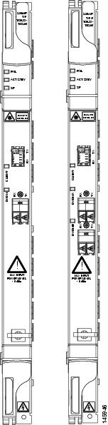
Figure 10-15 shows the TXP_MR_10E_C and TXP_MR_10E_L faceplates and block diagram.
Figure 10-15 TXP_MR_10E_C and TXP_MR_10E_L Faceplates and Block Diagram
For information on safety labels for the cards, see the “Class 1M Laser Product Cards” section.
10.5.3 Client Interface
The client interface is implemented with a separately orderable XFP module. The module is a tri-rate transceiver, providing a single port that can be configured in the field to support an OC-192 SR-1 (Telcordia GR-253-CORE) or STM-64 I-64.1 (ITU-T G.691) optical interface, as well as 10GE LAN PHY (10GBASE-LR), 10GE WAN PHY (10GBASE-LW), or 10G-FC signals.
The client side XFP pluggable module supports LC connectors and is equipped with a 1310-nm laser.
10.5.4 DWDM Trunk Interface
On the trunk side, the TXP_MR_10E_C and TXP_MR_10E_L cards provide a 10-Gbps STM-64/OC-192 interface. There are 80 tunable channels available in the 1550-nm C band or 82 tunable channels available in the 1580-nm L band on the 50-GHz ITU grid for the DWDM interface. The TXP_MR_10E_C and TXP_MR_10E_C cards provide 3R transponder functionality for this 10-Gbps trunk interface. Therefore, the card is suited for use in long-range amplified systems. The DWDM interface is compliant with ITU-T G.707, ITU-T G.709, and Telcordia GR-253-CORE standards.
The DWDM trunk port operates at a rate that is dependent on the input signal and the presence or absence of the ITU-T G.709 Digital Wrapper/FEC. The possible trunk rates are:
- OC192 (9.95328 Gbps)
- OTU2 (10.70923 Gbps)
- 10GE (10.3125 Gbps) or 10GE into OTU2 (ITU G.sup43 11.0957 Gbps)
- 10G-FC (10.51875 Gbps) or 10G-FC into OTU2 (nonstandard 11.31764 Gbps)
The maximum system reach in filterless applications without the use of optical amplification or regenerators is nominally rated at 23 dB over C-SMF fiber. This rating is not a product specification, but is given for informational purposes. It is subject to change.
10.5.5 Enhanced FEC (E-FEC) Feature
A key feature of the TXP_MR_10E_C and TXP_MR_10E_L cards is the availability to configure the forward error correction in three modes: NO FEC, FEC, and E-FEC. The output bit rate is always 10.7092 Gbps as defined in ITU-T G.709, but the error coding performance can be provisioned as follows:
10.5.6 FEC and E-FEC Modes
As client side traffic passes through the TXP_MR_10E_C and TXP_MR_10E_L cards, it can be digitally wrapped using FEC mode, E-FEC mode, or no error correction at all. The FEC mode setting provides a lower level of error detection and correction than the E-FEC mode setting of the card. As a result, using E-FEC mode allows higher sensitivity (lower OSNR) with a lower bit error rate than FEC mode. E-FEC enables longer distance trunk-side transmission than with FEC.
The E-FEC feature is one of three basic modes of FEC operation. FEC can be turned off, FEC can be turned on, or E-FEC can be turned on to provide greater range and lower BER. The default mode is FEC on and E-FEC off. E-FEC is provisioned using CTC.
10.5.7 Client-to-Trunk Mapping
The TXP_MR_10E_C and TXP_MR_10E_L cards can perform ODU2-to-OCh mapping, which allows operators to provision data payloads in a standard way across 10-Gbps optical links.
Digital wrappers that define client side interfaces are called ODU2 entities in ITU-T G.709. Digital wrappers that define trunk side interfaces are called OCh in ITU-T G.709. ODU2 digital wrappers can include G-MPLS signaling extensions to ITU-T G.709 (such as LSP and G-PID values) to define client interfaces and payload protocols.
10.5.8 Automatic Laser Shutdown
The ALS procedure is supported on both client and trunk interfaces. On the client interface, ALS is compliant with ITU-T G.664 (6/99). On the data application and trunk interface, the switch on and off pulse duration is greater than 60 seconds. The on and off pulse duration is user-configurable. For details regarding ALS provisioning for the TXP_MR_10E_C and TXP_MR_10E_L cards, refer to the Cisco ONS 15454 DWDM Procedure Guide.
10.5.9 TXP_MR_10E_C and TXP_MR_10E_L Card-Level Indicators
Table 10-7 lists the three card-level LEDs on the TXP_MR_10E_C and TXP_MR_10E_L cards.
10.5.10 TXP_MR_10E_C and TXP_MR_10E_L Port-Level Indicators
Table 10-8 lists the two port-level LEDs in the TXP_MR_10E_C and TXP_MR_10E_L cards.
10.6 TXP_MR_2.5G and TXPP_MR_2.5G Cards
The TXP_MR_2.5G card processes one 8-Mbps to 2.488-Gbps signal (client side) into one 8-Mbps to 2.5-Gbps, 100-GHz DWDM signal (trunk side). It provides one long-reach STM-16/OC-48 port per card, compliant with ITU-T G.707, ITU-T G.709, ITU-T G.957, and Telcordia GR-253-CORE.
The TXPP_MR_2.5G card processes one 8-Mbps to 2.488-Gbps signal (client side) into two 8-Mbps to 2.5-Gbps, 100-GHz DWDM signals (trunk side). It provides two long-reach STM-16/OC-48 ports per card, compliant with ITU-T G.707, ITU-T G.957, and Telcordia GR-253-CORE.
The TXP_MR_2.5G and TXPP_MR_2.5G cards are tunable over four wavelengths in the 1550-nm, ITU 100-GHz range. They are available in eight versions, each of which covers four wavelengths, for a total coverage of 32 different wavelengths in the 1550-nm range.
Note![]() ITU-T G.709 specifies a form of FEC that uses a “wrapper” approach. The digital wrapper lets you transparently take in a signal on the client side, wrap a frame around it, and restore it to its original form. FEC enables longer fiber links because errors caused by the optical signal degrading with distance are corrected.
ITU-T G.709 specifies a form of FEC that uses a “wrapper” approach. The digital wrapper lets you transparently take in a signal on the client side, wrap a frame around it, and restore it to its original form. FEC enables longer fiber links because errors caused by the optical signal degrading with distance are corrected.
The trunk/line port operates at up to 2.488 Gbps (or up to 2.66 Gbps with ITU-T G.709 Digital Wrapper/FEC) over unamplified distances up to 360 km (223.7 miles) with different types of fiber such as C-SMF or higher if dispersion compensation is used.
The TXP_MR_2.5G and TXPP_MR_2.5G cards support 2R (retime, regenerate) and 3R (retime, reshape, and regenerate) modes of operation where the client signal is mapped into a ITU-T G.709 frame. The mapping function is simply done by placing a digital wrapper around the client signal. Only OC-48/STM-16 client signals are fully ITU-T G.709 compliant, and the output bit rate depends on the input client signal. Table 10-9 shows the possible combinations of client interfaces, input bit rates, 2R and 3R modes, and ITU-T G.709 monitoring.
|
|
|
|
|
|---|---|---|---|
3R2 |
|||
|
|
Note![]() ITU-T G.709 and FEC support is disabled for all the 2R payload types in the TXP_MR_2.5G and TXPP_MR_2.5G cards.
ITU-T G.709 and FEC support is disabled for all the 2R payload types in the TXP_MR_2.5G and TXPP_MR_2.5G cards.
The output bit rate is calculated for the trunk bit rate by using the 255/238 ratio as specified in ITU-T G.709 for OTU1. Table 10-10 lists the calculated trunk bit rates for the client interfaces with ITU-T G.709 enabled.
|
|
|
|
|---|---|---|
For 2R operation mode, the TXP_MR_2.5G and TXPP_MR_2.5G cards have the ability to pass data through transparently from client side interfaces to a trunk side interface, which resides on an ITU grid. The data might vary at any bit rate from 200-Mbps up to 2.38-Gbps, including ESCON, DVB-ASI, ISC-1, and video signals. In this pass-through mode, no performance monitoring (PM) or digital wrapping of the incoming signal is provided, except for the usual PM outputs from the SFPs. Similarly, this card has the ability to pass data through transparently from the trunk side interfaces to the client side interfaces with bit rates varying from 200-Mbps up to 2.38-Gbps. Again, no PM or digital wrapping of received signals is available in this pass-through mode.
For 3R operation mode, the TXP_MR_2.5G and TXPP_MR_2.5G cards apply a digital wrapper to the incoming client interface signals (OC-N/STM-N, 1G-FC, 2G-FC, GE). PM is available on all of these signals except for 2G-FC, and varies depending upon the type of signal. For client inputs other than OC-48/STM-16, a digital wrapper might be applied but the resulting signal is not ITU-T G.709 compliant. The card applies a digital wrapper that is scaled to the frequency of the input signal.
The TXP_MR_2.5G and TXPP_MR_2.5G cards have the ability to take digitally wrapped signals in from the trunk interface, remove the digital wrapper, and send the unwrapped data through to the client interface. PM of the ITU-T G.709 OH and SONET/SDH OH is implemented.
10.6.1 Faceplate
Figure 10-16 shows the TXP_MR_2.5G and TXPP_MR_2.5G faceplates.
Figure 10-16 TXP_MR_2.5G and TXPP_MR_2.5G Faceplates
For information on safety labels for the cards, see the “Class 1M Laser Product Cards” section.
10.6.2 Block Diagram
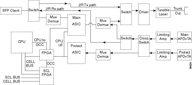
Figure 10-17 shows a block diagram of the TXP_MR_2.5G and TXPP_MR_2.5G cards.
Figure 10-17 TXP_MR_2.5G and TXPP_MR_2.5G Block Diagram
You can install TXP_MR_2.5G and TXPP_MR_2.5G cards in Slots 1 to 6 and 12 to 17. You can provision this card in a linear configuration. TXP_MR_10G and TXPP_MR_2.5G cards cannot be provisioned as a BLSR/MS-SPRing, a path protection/SNCP, or a regenerator. They can be used in the middle of BLSR/MS-SPRing or 1+1 spans only when the card is configured for transparent termination mode.
The TXP_MR_2.5G card features a 1550-nm laser for the trunk/line port and a 1310-nm laser for the client port. It contains two transmit and receive connector pairs (labeled) on the card faceplate. The card uses dual LC connectors for optical cable termination.
The TXPP_MR_2.5G card features a 1550-nm laser for the trunk/line port and a 1310-nm or 850-nm laser (depending on the SFP) for the client port and contains three transmit and receive connector pairs (labeled) on the card faceplate. The card uses dual LC connectors for optical cable termination.
10.6.3 Automatic Laser Shutdown
The ALS procedure is supported on both client and trunk interfaces. On the client interface, ALS is compliant with ITU-T G.664 (6/99). On the data application and trunk interface, the switch on and off pulse duration is greater than 60 seconds. The on and off pulse duration is user-configurable. For details regarding ALS provisioning for the TXP_MR_2.5G and TXPP_MR_2.5G cards, refer to the Cisco ONS 15454 DWDM Procedure Guide.
10.6.4 TXP_MR_2.5G and TXPP_MR_2.5G Card-Level Indicators
Table 10-11 lists the three card-level LEDs on the TXP_MR_2.5G and TXPP_MR_2.5G cards.
10.6.5 TXP_MR_2.5G and TXPP_MR_2.5G Port-Level Indicators
Table 10-12 lists the four port-level LEDs on the TXP_MR_2.5G and TXPP_MR_2.5G cards.
10.7 MXP_2.5G_10G Card
The MXP_2.5G_10G card multiplexes/demultiplexes four 2.5-Gbps signals (client side) into one 10-Gbps, 100-GHz DWDM signal (trunk side). It provides one extended long-range STM-64/OC-192 port per card on the trunk side (compliant with ITU-T G.707, ITU-T G.709, ITU-T G.957, and Telcordia GR-253-CORE) and four intermediate- or short-range OC-48/STM-16 ports per card on the client side. The port operates at 9.95328 Gbps over unamplified distances up to 80 km (50 miles) with different types of fiber such as C-SMF or dispersion compensated fiber limited by loss and/or dispersion.
Client ports on the MXP_2.5G_10G card are also interoperable with SONET OC-1 (STS-1) fiber optic signals defined in Telcordia GR-253-CORE. An OC-1 signal is the equivalent of one DS-3 channel transmitted across optical fiber. OC-1 is primarily used for trunk interfaces to phone switches in the United States. There is no SDH equivalent for SONET OC-1.
The MXP_2.5G_10G card is tunable over two neighboring wavelengths in the 1550-nm, ITU 100-GHz range. It is available in 16 different versions, each of which covers two wavelengths, for a total coverage of 32 different wavelengths in the 1550-nm range.
Note![]() ITU-T G.709 specifies a form of FEC that uses a “wrapper” approach. The digital wrapper lets you transparently take in a signal on the client side, wrap a frame around it and restore it to its original form. FEC enables longer fiber links because errors caused by the optical signal degrading with distance are corrected.
ITU-T G.709 specifies a form of FEC that uses a “wrapper” approach. The digital wrapper lets you transparently take in a signal on the client side, wrap a frame around it and restore it to its original form. FEC enables longer fiber links because errors caused by the optical signal degrading with distance are corrected.
The port can also operate at 10.70923 Gbps in ITU-T G.709 Digital Wrapper/FEC mode.
You can install MXP_2.5G_10G cards in Slots 1 to 6 and 12 to 17.
You can provision this card in a linear configuration. MXP_2.5G_10G cards cannot be provisioned as a BLSR/MS-SPRing, a path protection/SNCP, or a regenerator. They can be used in the middle of BLSR/MS-SPRing or 1+1 spans only when the card is configured for transparent termination mode.
The MXP_2.5G_10G port features a 1550-nm laser on the trunk port and four 1310-nm lasers on the client ports and contains five transmit and receive connector pairs (labeled) on the card faceplate. The card uses a dual LC connector on the trunk side and SFP connectors on the client side for optical cable termination.
Note![]() When you create a 4xOC-48 OCHCC circuit, you need to select the G.709 and Synchronous options. A 4xOC-48 OCHCC circuit is supported by G.709 and synchronous mode. This is necessary to provision a 4xOC-48 OCHCC circuit.
When you create a 4xOC-48 OCHCC circuit, you need to select the G.709 and Synchronous options. A 4xOC-48 OCHCC circuit is supported by G.709 and synchronous mode. This is necessary to provision a 4xOC-48 OCHCC circuit.
Figure 10-18 shows the MXP_2.5G_10G faceplate.
Figure 10-18 MXP_2.5G_10G Faceplate
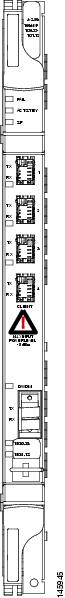
For information on safety labels for the card, see the “Class 1 Laser Product Cards” section.
Figure 10-19 shows a block diagram of the MXP_2.5G_10G card.
Figure 10-19 MXP_2.5G_10G Card Block Diagram
10.7.1 Timing Synchronization
The MXP_2.5G_10G card is synchronized to the TCC2/TCC2P clock during normal conditions and transmits the ITU-T G.709 frame using this clock. The TCC2/TCC2P card can operate from an external building integrated timing supply (BITS) clock, an internal Stratum 3 clock, or from clock recovered from one of the four valid client clocks. If clocks from both TCC2/TCC2P cards are not available, the MXP_2.5G_10G card switches automatically (with errors, not hitless) to an internal 19.44 MHz clock that does not meet SONET clock requirements. This will result in a clock alarm.
10.7.2 Automatic Laser Shutdown
The ALS procedure is supported on both client and trunk interfaces. On the client interface, ALS is compliant with ITU-T G.664 (6/99). On the data application and trunk interface, the switch on and off pulse duration is greater than 60 seconds. The on and off pulse duration is user-configurable. For details regarding ALS provisioning for the MXP_2.5G_10G card, refer to the Cisco ONS 15454 DWDM Procedure Guide.
10.7.3 MXP_2.5G_10G Card-Level Indicators
Table 10-13 describes the three card-level LEDs on the MXP_2.5G_10G card.
10.7.3.1 MXP_2.5G_10G Port-Level Indicators
Table 10-14 describes the four port-level LEDs on the MXP_2.5G_10G card.
10.7.4 MXP_2.5G_10E Card
The faceplate designation of the card is “4x2.5G 10E MXP.” The MXP_2.5G_10E card is a DWDM muxponder for the ONS 15454 platform that supports full transparent termination the client side. The card multiplexes four 2.5 Gbps client signals (4 x OC48/STM-16 SFP) into a single 10-Gbps DWDM optical signal on the trunk side. The MXP_2.5G_10E provides wavelength transmission service for the four incoming 2.5 Gbps client interfaces. The MXP_2.5G_10E muxponder passes all SONET/SDH overhead bytes transparently.
The digital wrapper function (ITU-T G.709 compliant) formats the DWDM wavelength so that it can be used to set up generic communications channels (GCCs) for data communications, enable FEC, or facilitate performance monitoring.
The MXP_2.5G_10E works with optical transport network (OTN) devices defined in ITU-T G.709. The card supports ODU1 to OTU2 multiplexing, an industry standard method for asynchronously mapping a SONET/SDH payload into a digitally wrapped envelope. See the “Multiplexing Function” section.
The MXP_2.5G_10E card is not compatible with the MXP_2.5G_10G card, which does not support full transparent termination. You can install MXP_2.5G_10E cards in Slots 1 to 6 and 12 to 17. You can provision this card in a linear configuration, as a BLSR/MS-SPRing, a path protection/SNCP, or a regenerator. The card can be used in the middle of BLSR/MS-SPRing or 1+1 spans when the card is configured for transparent termination mode.
The MXP_2.5G_10E features a 1550-nm laser on the trunk port and four 1310-nm lasers on the client ports and contains five transmit and receive connector pairs (labeled) on the card faceplate. The card uses a dual LC connector on the trunk side and uses SFP modules on the client side for optical cable termination. The SFP pluggable modules are short reach (SR) or intermediate reach (IR) and support an LC fiber connector.
Note![]() When you create a 4xOC-48 OCHCC circuit, you need to select the G.709 and Synchronous options. A 4xOC-48 OCHCC circuit is supported by G.709 and synchronous mode. This is necessary to provision a 4xOC-48 OCHCC circuit.
When you create a 4xOC-48 OCHCC circuit, you need to select the G.709 and Synchronous options. A 4xOC-48 OCHCC circuit is supported by G.709 and synchronous mode. This is necessary to provision a 4xOC-48 OCHCC circuit.
10.7.4.1 Key Features
The MXP_2.5G_10E card has the following high level features:
- Four 2.5 Gbps client interfaces (OC-48/STM-16) and one 10 Gbps trunk. The four OC-48 signals are mapped into a ITU-T G.709 OTU2 signal using standard ITU-T G.709 multiplexing.
- Onboard E-FEC processor: The processor supports both standard Reed-Solomon (RS, specified in ITU-T G.709) and E-FEC, which allows an improved gain on trunk interfaces with a resultant extension of the transmission range on these interfaces. The E-FEC functionality increases the correction capability of the transponder to improve performance, allowing operation at a lower OSNR compared to the standard RS (237,255) correction algorithm. A new block code (BCH) algorithm implemented in E-FEC allows recovery of an input BER up to 1E-3.
- Pluggable client interface optic modules: The MXP_2.5G_10E card has modular interfaces. Two types of optics modules can be plugged into the card. These include an OC-48/STM 16 SR-1 interface with a 7-km (4.3-mile) nominal range (for short range and intra-office applications) and an IR-1 interface with a range up to 40 km (24.9 miles). SR-1 is defined in Telcordia GR-253-CORE and in I-16 (ITU-T G.957). IR-1 is defined in Telcordia GR-253-CORE and in S-16-1 (ITU-T G.957).
- High level provisioning support: The MXP_2.5G_10E card is initially provisioned using Cisco TransportPlanner software. Subsequently, the card can be monitored and provisioned using CTC software.
- Link monitoring and management: The MXP_2.5G_10E card uses standard OC-48 OH (overhead) bytes to monitor and manage incoming interfaces. The card passes the incoming SDH/SONET data stream and its overhead bytes transparently.
- Control of layered SONET/SDH transport overhead: The card is provisionable to terminate regenerator section overhead. This is used to eliminate forwarding of unneeded layer overhead. It can help reduce the number of alarms and help isolate faults in the network.
- Automatic timing source synchronization: The MXP_2.5G_10E normally synchronizes from the TCC2/TCC2P card. If for some reason, such as maintenance or upgrade activity, the TCC2/TCC2P is not available, the MXP_2.5G_10E automatically synchronizes to one of the input client interface clocks.
- Configurable squelching policy: The card can be configured to squelch the client interface output if there is LOS at the DWDM receiver or if there is a remote fault. In the event of a remote fault, the card manages multiplex section alarm indication signal (MS-AIS) insertion.
10.7.5 Faceplate
Figure 10-20 shows the MXP_2.5G_10E faceplate.
Figure 10-20 MXP_2.5G_10E Faceplate
For information on safety labels for the card, see the “Class 1 Laser Product Cards” section.
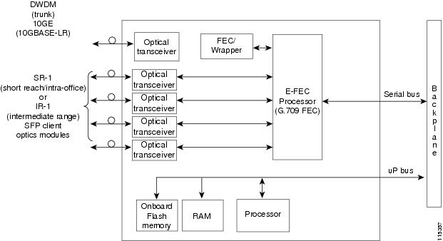
Figure 10-21 shows a block diagram of the MXP_2.5G_10E card.
Figure 10-21 MXP_2.5G_10E Block Diagram
10.7.6 Client Interfaces
The MXP_2.5G_10E provides four intermediate- or short-range OC-48/STM-16 ports per card on the client side. Both SR-1 or IR-1 optics can be supported and the ports use SFP connectors. The client interfaces use four wavelengths in the 1310-nm, ITU 100-MHz-spaced, channel grid.
10.7.6.1 DWDM Interface
The MXP_2.5G_10E serves as an OTN multiplexer, transparently mapping four OC-48 channels asynchronously to ODU1 into one 10-Gbps trunk. The DWDM trunk is tunable for transmission over four wavelengths in the 1550-nm, ITU 100-GHz spaced channel grid.
10.7.7 Multiplexing Function
The muxponder is an integral part of the reconfigurable optical add/drop multiplexer (ROADM) network. The key function of MXP_2.5G_10E is to multiplex 4 OC-48/STM16 signals onto one ITU-T G.709 OTU2 optical signal (DWDM transmission). The multiplexing mechanism allows the signal to be terminated at a far-end node by another MXP_2.5G_10E card.
Termination mode transparency on the muxponder is configured using OTUx and ODUx OH bytes. The ITU-T G.709 specification defines OH byte formats that are used to configure, set, and monitor frame alignment, FEC mode, section monitoring, tandem connection monitoring, and termination mode transparency.
The MXP_2.5G_10E card performs ODU to OTU multiplexing as defined in ITU-T G.709. The ODU is the framing structure and byte definition (ITU-T G.709 digital wrapper) used to define the data payload coming into one of the SONET/SDH client interfaces on MXP_2.5G_10E. The term ODU1 refers to an ODU that operates at 2.5-Gbps line rate. On the MXP_2.5G_10E, there are four client interfaces that can be defined using ODU1 framing structure and format by asserting a ITU-T G.709 digital wrapper.
The output of the muxponder is a single 10-Gbps DWDM trunk interface defined using OTU2. It is within the OTU2 framing structure that FEC or E-FEC information is appended to enable error checking and correction.
10.7.8 Timing Synchronization
The MXP_2.5G_10E card is synchronized to the TCC2/TCC2P clock during normal conditions and transmits the ITU-T G.709 frame using this clock. No holdover function is implemented. If neither TCC2/TCC2P clock is available, the MXP_2.5G_10E switches automatically (hitless) to the first of the four valid client clocks with no time restriction as to how long it can run on this clock. The MXP_2.5G_10E continues to monitor the TCC2/TCC2P card. If a TCC2/TCC2P card is restored to working order, the MXP_2.5G_10E reverts to the normal working mode of running from the TCC2/TCC2P clock. If there is no valid TCC2/TCC2P clock and all of the client channels become invalid, the card waits (no valid frames processed) until one of the TCC2/TCC2P cards supplies a valid clock. In addition, the card is allowed to select the recovered clock from one active and valid client channel and supply that clock to the TCC2/TCC2P card.
10.7.9 Enhanced FEC (E-FEC) Capability
The MXP_2.5G_10E can configure the FEC in three modes: NO FEC, FEC, and E-FEC. The output bit rate is always 10.7092 Gbps as defined in ITU-T G.709, but the error coding performance can be provisioned as follows:
- NO FEC—No FEC
- FEC—Standard ITU-T G.975 Reed-Solomon algorithm
- E-FEC—Standard ITU-T G.975.1 I.7, two orthogonally concatenated BCH super FEC code. This FEC scheme contains three parameterizations of the same scheme of two orthogonally interleaved BCH. The constructed code is decoded iteratively to achieve the expected performance.
10.7.10 FEC and E-FEC Modes
As client side traffic passes through the MXP_2.5G_10E card, it can be digitally wrapped using FEC mode error correction or E-FEC mode error correction (or no error correction at all). The FEC mode setting provides a lower level of error detection and correction than the E-FEC mode setting of the card. As a result, using E-FEC mode allows higher sensitivity (lower OSNR) with a lower BER than FEC mode. E-FEC enables longer distance trunk-side transmission than with FEC.
The E-FEC feature is one of three basic modes of FEC operation. FEC can be turned off, FEC can be turned on, or E-FEC can be turned on to provide greater range and lower BER. The default mode is FEC on and E-FEC off. E-FEC is provisioned using CTC.
10.7.11 SONET/SDH Overhead Byte Processing
The card passes the incoming SONET/SDH data stream and its overhead bytes for the client signal transparently. The card can be provisioned to terminate regenerator section overhead. This is used to eliminate forwarding of unneeded layer overhead. It can help reduce the number of alarms and help isolate faults in the network.
10.7.12 Client Interface Monitoring
The following parameters are monitored on the MXP_2.5G_10E card:
- Laser bias current is measured as a PM parameter
- LOS is detected and signaled
- Transmit (TX) and receive (RX) power are monitored
The following parameters are monitored in real time mode (one second):
In case of loss of communication (LOC) at the DWDM receiver or far-end LOS, the client interface behavior is configurable. AIS can be invoked or the client signal can be squelched.
10.7.13 Wavelength Identification
The card uses trunk lasers that are wave-locked, which allows the trunk transmitter to operate on the ITU grid effectively. Table 10-15 describes the required trunk transmit laser wavelengths. The laser is tunable over eight wavelengths at 50-GHz spacing or four at 100-GHz spacing.
|
|
|
|---|---|
10.7.14 Automatic Laser Shutdown
The ALS procedure is supported on both client and trunk interfaces. On the client interface, ALS is compliant with ITU-T G.664 (6/99). On the data application and trunk interface, the switch on and off pulse duration is greater than 60 seconds. The on and off pulse duration is user-configurable. For details regarding ALS provisioning for the MXP_2.5G_10E card, refer to the Cisco ONS 15454 DWDM Procedure Guide.
10.7.15 Jitter
For SONET and SDH signals, the MXP_2.5G_10E card complies with Telcordia GR-253-CORE, ITU-T G.825, and ITU-T G.873 for jitter generation, jitter tolerance, and jitter transfer. See the “Jitter Considerations” section for more information.
10.7.16 Lamp Test
The MXP_2.5G_10E card supports a lamp test function that is activated from the ONS 15454 front panel or through CTC to ensure that all LEDs are functional.
10.7.17 Onboard Traffic Generation
The MXP_2.5G_10E card provides internal traffic generation for testing purposes according to pseudo-random bit sequence (PRBS), SONET/SDH, or ITU-T G.709.
10.7.18 MXP_2.5G_10E Card-Level Indicators
Table 10-16 describes the three card-level LEDs on the MXP_2.5G_10E card.
10.7.19 MXP_2.5G_10E Port-Level Indicators
Table 10-17 describes the port-level LEDs on the MXP_2.5G_10E card.
10.8 MXP_2.5G_10E_C and MXP_2.5G_10E_L Cards
The MXP_2.5G_10E_C and MXP_2.5G_10E_L cards are DWDM muxponders for the ONS 15454 platform that support transparent termination mode on the client side. The faceplate designation of the cards is “4x2.5G 10E MXP C” for the MXP_2.5G_10E_C card and “4x2.5G 10E MXP L” for the MXP_2.5G_10E_L card. The cards multiplex four 2.5-Gbps client signals (4 x OC48/STM-16 SFP) into a single 10-Gbps DWDM optical signal on the trunk side. The MXP_2.5G_10E_C and MXP_2.5G_10E_L cards provide wavelength transmission service for the four incoming 2.5 Gbps client interfaces. The MXP_2.5G_10E_C and MXP_2.5G_10E_L muxponders pass all SONET/SDH overhead bytes transparently.
The digital wrapper function (ITU-T G.709 compliant) formats the DWDM wavelength so that it can be used to set up GCCs for data communications, enable FEC, or facilitate PM.
The MXP_2.5G_10E_C and MXP_2.5G_10E_L cards work with OTN devices defined in ITU-T G.709. The cards support ODU1 to OTU2 multiplexing, an industry standard method for asynchronously mapping a SONET/SDH payload into a digitally wrapped envelope. See the “Multiplexing Function” section.
The MXP_2.5G_10E_C and MXP_2.5G_10E_L cards are not compatible with the MXP_2.5G_10G card, which does not support transparent termination mode.
You can install MXP_2.5G_10E_C and MXP_2.5G_10E_L cards in Slots 1 to 6 and 12 to 17. You can provision a card in a linear configuration, as a BLSR/MS-SPRing, a path protection/SNCP, or a regenerator. The cards can be used in the middle of BLSR/MS-SPRing or 1+1 spans when the cards are configured for transparent termination mode.
The MXP_2.5G_10E_C card features a tunable 1550-nm C-band laser on the trunk port. The laser is tunable across 82 wavelengths on the ITU grid with 50-GHz spacing between wavelengths. The MXP_2.5G_10E_L features a tunable 1580-nm L-band laser on the trunk port. The laser is tunable across 80 wavelengths on the ITU grid, also with 50-GHz spacing. Each card features four 1310-nm lasers on the client ports and contains five transmit and receive connector pairs (labeled) on the card faceplate. The cards uses dual LC connectors on the trunk side and use SFP modules on the client side for optical cable termination. The SFP pluggable modules are SR or IR and support an LC fiber connector.
Note![]() When you create a 4xOC-48 OCHCC circuit, you need to select the G.709 and Synchronous options. A 4xOC-48 OCHCC circuit is supported by G.709 and synchronous mode. This is necessary to provision a 4xOC-48 OCHCC circuit.
When you create a 4xOC-48 OCHCC circuit, you need to select the G.709 and Synchronous options. A 4xOC-48 OCHCC circuit is supported by G.709 and synchronous mode. This is necessary to provision a 4xOC-48 OCHCC circuit.
10.8.1 Key Features
The MXP_2.5G_10E_C and MXP_2.5G_10E_L cards have the following high level features:
- Four 2.5 Gbps client interfaces (OC-48/STM-16) and one 10 Gbps trunk. The four OC-48 signals are mapped into a ITU-T G.709 OTU2 signal using standard ITU-T G.709 multiplexing.
- Onboard E-FEC processor: The processor supports both standard RS (specified in ITU-T G.709) and E-FEC, which allows an improved gain on trunk interfaces with a resultant extension of the transmission range on these interfaces. The E-FEC functionality increases the correction capability of the transponder to improve performance, allowing operation at a lower OSNR compared to the standard RS (237,255) correction algorithm. A new BCH algorithm implemented in E-FEC allows recovery of an input BER up to 1E-3.
- Pluggable client interface optic modules: The MXP_2.5G_10E_C and MXP_2.5G_10E_L cards have modular interfaces. Two types of optics modules can be plugged into the card. These include an OC-48/STM 16 SR-1 interface with a 7-km (4.3-mile) nominal range (for short range and intra-office applications) and an IR-1 interface with a range up to 40 km (24.9 miles). SR-1 is defined in Telcordia GR-253-CORE and in I-16 (ITU-T G.957). IR-1 is defined in Telcordia GR-253-CORE and in S-16-1 (ITU-T G.957).
- High level provisioning support: The cards are initially provisioned using Cisco TransportPlanner software. Subsequently, the card can be monitored and provisioned using CTC software.
- Link monitoring and management: The cards use standard OC-48 OH (overhead) bytes to monitor and manage incoming interfaces. The cards pass the incoming SDH/SONET data stream and its overhead bytes transparently.
- Control of layered SONET/SDH transport overhead: The cards are provisionable to terminate regenerator section overhead. This is used to eliminate forwarding of unneeded layer overhead. It can help reduce the number of alarms and help isolate faults in the network.
- Automatic timing source synchronization: The MXP_2.5G_10E_C and MXP_2.5G_10E_L cards normally synchronize from the TCC2/TCC2P card. If for some reason, such as maintenance or upgrade activity, the TCC2/TCC2P is not available, the cards automatically synchronize to one of the input client interface clocks.
- Configurable squelching policy: The cards can be configured to squelch the client interface output if there is LOS at the DWDM receiver or if there is a remote fault. In the event of a remote fault, the card manages MS-AIS insertion.
- The cards are tunable across the full C band (MXP_2.5G_10E_C) or full L band (MXP_2.5G_10E_L), thus eliminating the need to use different versions of each card to provide tunability across specific wavelengths in a band.
10.8.2 Faceplate
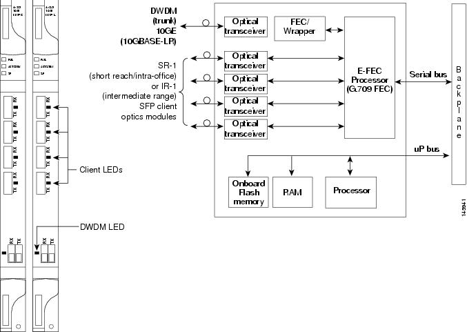
Figure 10-22 shows the MXP_2.5G_10E_C and MXP_2.5G_10E_L faceplates and block diagram.
Figure 10-22 MXP_2.5G_10E _C and MXP_2.5G_10E_L Faceplates and Block Diagram
For information on safety labels for the cards, see the “Class 1 Laser Product Cards” section.
10.8.3 Client Interfaces
The MXP_2.5G_10E_C and MXP_2.5G_10E_L cards provide four intermediate- or short-range OC-48/STM-16 ports per card on the client side. Both SR-1 and IR-1 optics can be supported and the ports use SFP connectors. The client interfaces use four wavelengths in the 1310-nm, ITU 100-GHz-spaced, channel grid.
10.8.4 DWDM Interface
The MXP_2.5G_10E_C and MXP_2.5G_10E_L cards serve as OTN multiplexers, transparently mapping four OC-48 channels asynchronously to ODU1 into one 10-Gbps trunk. For the MXP_2.5G_10E_C card, the DWDM trunk is tunable for transmission over the entire C band and for the MXP_2.5G_10E_L card, the DWDM trunk is tunable for transmission over the entire L band. Channels are spaced at 50-GHz on the ITU grid.
10.8.5 Multiplexing Function
The muxponder is an integral part of the ROADM network. The key function of the MXP_2.5G_10E_C and MXP_2.5G_10E_L cards is to multiplex four OC-48/STM16 signals onto one ITU-T G.709 OTU2 optical signal (DWDM transmission). The multiplexing mechanism allows the signal to be terminated at a far-end node by another similar card.
Transparent termination on the muxponder is configured using OTUx and ODUx OH bytes. The ITU-T G.709 specification defines OH byte formats that are used to configure, set, and monitor frame alignment, FEC mode, section monitoring, tandem connection monitoring, and transparent termination mode.
The MXP_2.5G_10E and MXP_2.5G_10E_L cards perform ODU to OTU multiplexing as defined in ITU-T G.709. The ODU is the framing structure and byte definition (ITU-T G.709 digital wrapper) used to define the data payload coming into one of the SONET/SDH client interfaces on the cards. The term ODU1 refers to an ODU that operates at 2.5-Gbps line rate. On the cards, there are four client interfaces that can be defined using ODU1 framing structure and format by asserting a ITU-T G.709 digital wrapper.
The output of the muxponder is a single 10-Gbps DWDM trunk interface defined using OTU2. It is within the OTU2 framing structure that FEC or E-FEC information is appended to enable error checking and correction.
10.8.6 Timing Synchronization
The MXP_2.5G_10E_C and MXP_2.5G_10E_L cards are synchronized to the TCC2/TCC2P clock during normal conditions and transmit the ITU-T G.709 frame using this clock. No holdover function is implemented. If neither TCC2/TCC2P clock is available, the card switches automatically (hitless) to the first of the four valid client clocks with no time restriction as to how long it can run on this clock. The card continues to monitor the TCC2/TCC2P card. If a TCC2/TCC2P card is restored to working order, the card reverts to the normal working mode of running from the TCC2/TCC2P clock. If there is no valid TCC2/TCC2P clock and all of the client channels become invalid, the card waits (no valid frames processed) until one of the TCC2/TCC2P cards supplies a valid clock. In addition, the card is allowed to select the recovered clock from one active and valid client channel and supply that clock to the TCC2/TCC2P card.
10.8.7 Enhanced FEC (E-FEC) Capability
The MXP_2.5G_10E_C and MXP_2.5G_10E_L cards can configure the FEC in three modes: NO FEC, FEC, and E-FEC. The output bit rate is always 10.7092 Gbps as defined in ITU-T G.709, but the error coding performance can be provisioned as follows:
- NO FEC—No FEC
- FEC—Standard ITU-T G.975 Reed-Solomon algorithm
- E-FEC—Standard ITU-T G.975.1 I.7, two orthogonally concatenated BCH super FEC code. This FEC scheme contains three parameterizations of the same scheme of two orthogonally interleaved block codes (BCH). The constructed code is decoded iteratively to achieve the expected performance.
10.8.8 FEC and E-FEC Modes
As client side traffic passes through the card, it can be digitally wrapped using FEC mode error correction or E-FEC mode error correction (or no error correction at all). The FEC mode setting provides a lower level of error detection and correction than the E-FEC mode setting of the card. As a result, using E-FEC mode allows higher sensitivity (lower OSNR) with a lower BER than FEC mode. E-FEC enables longer distance trunk-side transmission than with FEC.
The E-FEC feature is one of three basic modes of FEC operation. FEC can be turned off, FEC can be turned on, or E-FEC can be turned on to provide greater range and lower BER. The default mode is FEC on and E-FEC off. E-FEC is provisioned using CTC.
10.8.9 SONET/SDH Overhead Byte Processing
The card passes the incoming SONET/SDH data stream and its overhead bytes for the client signal transparently. The card can be provisioned to terminate regenerator section overhead. This is used to eliminate forwarding of unneeded layer overhead. It can help reduce the number of alarms and help isolate faults in the network.
10.8.10 Client Interface Monitoring
The following parameters are monitored on the MXP_2.5G_10E_C and MXP_2.5G_10E_L cards:
- Laser bias current is measured as a PM parameter.
- LOS is detected and signaled.
- Rx and Tx power are monitored.
The following parameters are monitored in real time mode (one second):
In case of LOC at the DWDM receiver or far-end LOS, the client interface behavior is configurable. AIS can be invoked or the client signal can be squelched.
10.8.11 Wavelength Identification
The card uses trunk lasers that are wavelocked, which allows the trunk transmitter to operate on the ITU grid effectively. Both the MXP_2.5G_10E_C and MXP_2.5G_10E_L cards implement the UT2 module. The MXP_2.5G_10E_C card uses a C-band version of the UT2 and the MXP_2.5G_10E_L card uses an L-band version.
Table 10-18 describes the required trunk transmit laser wavelengths for the MXP_2.5G_10E_C card. The laser is tunable over 82 wavelengths in the C band at 50-GHz spacing on the ITU grid.
|
|
|
|
|
|
|
|---|---|---|---|---|---|
Table 10-19 describes the required trunk transmit laser wavelengths for the MXP_2.5G_10E_L card. The laser is fully tunable over 80 wavelengths in the L band at 50-GHz spacing on the ITU grid.
|
|
|
|
|
|
|
|---|---|---|---|---|---|
10.8.12 Automatic Laser Shutdown
The ALS procedure is supported on both client and trunk interfaces. On the client interface, ALS is compliant with ITU-T G.664 (6/99). On the data application and trunk interface, the switch on and off pulse duration is greater than 60 seconds. The on and off pulse duration is user-configurable. For details regarding ALS provisioning for the MXP_2.5G_10E_C and MXP_2.5G_10E_L cards, see the Cisco ONS 15454 DWDM Procedure Guide.
10.8.13 Jitter
For SONET and SDH signals, the MXP_2.5G_10E_C and MXP_2.5G_10E_L cards comply with Telcordia GR-253-CORE, ITU-T G.825, and ITU-T G.873 for jitter generation, jitter tolerance, and jitter transfer. See the “Jitter Considerations” section for more information.
10.8.14 Lamp Test
The MXP_2.5G_10E_C and MXP_2.5G_10E_L cards support a lamp test function that is activated from the ONS 15454 front panel or through CTC to ensure that all LEDs are functional.
10.8.15 Onboard Traffic Generation
The MXP_2.5G_10E_C and MXP_2.5G_10E_L cards provide internal traffic generation for testing purposes according to PRBS, SONET/SDH, or ITU-T G.709.
10.8.16 MXP_2.5G_10E_C and MXP_2.5G_10E_L Card-Level Indicators
Table 10-20 describes the three card-level LEDs on the MXP_2.5G_10E_C and MXP_2.5G_10E_L cards.
10.8.17 MXP_2.5G_10E and MXP_2.5G_10E_L Port-Level Indicators
Table 10-21 describes the port-level LEDs on the MXP_2.5G_10E_C and MXP_2.5G_10E_L cards.
10.9 MXP_MR_2.5G and MXPP_MR_2.5G Cards
The MXP_MR_2.5G card aggregates a mix and match of client Storage Area Network (SAN) service client inputs (GE, FICON, Fibre Channel, and ESCON) into one 2.5 Gbps STM-16/OC-48 DWDM signal on the trunk side. It provides one long-reach STM-16/OC-48 port per card and is compliant with Telcordia GR-253-CORE.
Note![]() In Software Release 7.0 and later, two additional operating modes have been made available to the user: pure ESCON (all 8 ports running ESCON), and mixed mode (Port 1 running FC/GE/FICON, and Ports 5 through 8 running ESCON). When the card is part of a system running Software Release 6.0 or below, only one operating mode, (FC/GE) is available for use.
In Software Release 7.0 and later, two additional operating modes have been made available to the user: pure ESCON (all 8 ports running ESCON), and mixed mode (Port 1 running FC/GE/FICON, and Ports 5 through 8 running ESCON). When the card is part of a system running Software Release 6.0 or below, only one operating mode, (FC/GE) is available for use.
The 2.5-Gbps Multirate Muxponder–Protected–100 GHz–Tunable 15xx.xx-15yy.yy (MXPP_MR_2.5G) card aggregates various client SAN service client inputs (GE, FICON, Fibre Channel, and ESCON) into one 2.5 Gbps STM-16/OC-48 DWDM signal on the trunk side. It provides two long-reach STM-16/OC-48 ports per card and is compliant with ITU-T G.957 and Telcordia GR-253-CORE.
Because the cards are tunable to one of four adjacent grid channels on a 100-GHz spacing, each card is available in eight versions, with 15xx.xx representing the first wavelength and 15yy.yy representing the last wavelength of the four available on the card. In total, 32 DWDM wavelengths are covered in accordance with the ITU-T 100-GHz grid standard, G.692, and Telcordia GR-2918-CORE, Issue 2. The card versions along with their corresponding wavelengths are shown in Table 10-22 .
|
|
|
|||
|---|---|---|---|---|
The muxponders are intended to be used in applications with long DWDM metro or regional unregenerated spans. Long transmission distances are achieved through the use of flat gain optical amplifiers.
The client interface supports the following payload types:
Note![]() Because the client payload cannot oversubscribe the trunk, a mix of client signals can be accepted, up to a maximum limit of 2.5 Gbps.
Because the client payload cannot oversubscribe the trunk, a mix of client signals can be accepted, up to a maximum limit of 2.5 Gbps.
Table 10-23 shows the input data rate for each client interface, and the encapsulation method. The current version of the ITU-T Transparent Generic Framing Procedure (GFP-T) G.7041 supports transparent mapping of 8B/10B block-coded protocols, including Gigabit Ethernet, Fibre Channel, and FICON.
In addition to the GFP mapping, 1-Gbps traffic on Port 1 or 2 of the high-speed serializer/deserializer (SERDES) is mapped to an STS-24c channel. If two 1-Gbps client signals are present at Port 1 and Port 2 of the SERDES, the Port 1 signal is mapped into the first STS-24c channel and the Port 2 signal into the second STS-24c channel. The two channels are then mapped into an OC-48 trunk channel.
|
|
|
|
|---|---|---|
Table 10-24 shows some of the mix and match possibilities on the various client ports. The table is intended to show the full client payload configurations for the card.
|
|
|
|
|---|---|---|
10.9.1 Performance Monitoring
GFP-T performance monitoring (GFP-T PM) is available via remote monitoring (RMON), and trunk PM is managed according to Telcordia GR-253-CORE and ITU G.783/826. Client PM is achieved through RMON for FC and GE.
10.9.2 Distance Extension
A buffer-to-buffer credit management scheme provides FC flow control. With this feature enabled, a port indicates the number of frames that can be sent to it (its buffer credit), before the sender is required to stop transmitting and wait for the receipt of a “ready” indication The MXP_MR_2.5G and MXPP_MR_2.5 cards support FC credit-based flow control with a buffer-to-buffer credit extension of up to 1600 km (994.2 miles) for 1G FC and up to 800 km (497.1 miles) for 2G FC. The feature can be enabled or disabled.
10.9.3 Slot Compatibility
You can install MXP_MR_2.5G and MXPP_MR_2.5G cards in Slots 1 to 6 and 12 to 17. The TCC2/TCC2P card is the only other card required to be used with these muxponder cards. Cross-connect cards do not affect the operation of the muxponder cards.
10.9.4 Interoperability with Cisco MDS Switches
You can provision a string (port name) for each fiber channel/FICON interface on the MXP_MR_2.5G and MXPP_MR_2.5G cards, which allows the MDS Fabric Manager to create a link association between that SAN port and a SAN port on a Cisco MDS 9000 switch.
10.9.5 Client and Trunk Ports
The MXP_MR_2.5G card features a 1550-nm laser for the trunk/line port and a 1310-nm or 850-nm laser (depending on the SFP) for the client ports. The card contains eight 12.5 degree downward tilt SFP modules for the client interfaces. For optical termination, each SFP uses two LC connectors, which are labeled TX and RX on the faceplate. The trunk port is a dual-LC connector with a 45 degree downward angle.
The MXPP_MR_2.5G card features a 1550-nm laser for the trunk/line port and a 1310-nm or 850-nm laser (depending on the SFP) for the client port. The card contains eight 12.5 degree downward tilt SFP modules for the client interfaces. For optical termination, each SFP uses two LC connectors, which are labeled TX and RX on the faceplate. There are two trunk port connectors (one for working and one for protect). Each is a dual-LC connector with a 45-degree downward angle.
10.9.6 Faceplates
Figure 10-23 shows the MXP_MR_2.5G and MXPP_MR_2.5G faceplates.
Figure 10-23 MXP_MR_2.5G and MXPP_MR_2.5G Faceplates
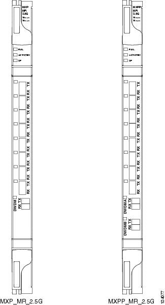
For information on safety labels for the cards, see the “Class 1M Laser Product Cards” section.
10.9.7 Block Diagram
Figure 10-24 shows a block diagram of the MXP_MR_2.5G card. The card has eight SFP client interfaces. Ports 1 and 2 can be used for GE, FC, FICON, or ESCON. Ports 3 through 8 are used for ESCON client interfaces. There are two SERDES blocks dedicated to the high-speed interfaces (GE, FC, FICON, and ESCON) and two SERDES blocks for the ESCON interfaces. A FPGA is provided to support different configurations for different modes of operation. This FPGA has a Universal Test and Operations Physical Interface for ATM (UTOPIA) interface. A transceiver add/drop multiplexer (TADM) chip supports framing. Finally, the output signal is serialized and connected to the trunk front end with a direct modulation laser. The trunk receive signal is converted into an electrical signal with an avalanche photodiode (APD), is deserialized, and is then sent to the TADM framer and FPGA.
The MXPP_MR_2.5G is the same, except a 50/50 splitter divides the power at the trunk interface. In the receive direction, there are two APDs, two SERDES blocks, and two TADM framers. This is necessary to monitor both the working and protect paths. A switch selects one of the two paths to connect to the client interface.
Figure 10-24 MXP_MR_2.5G and MXPP_MR_2.5G Block Diagram
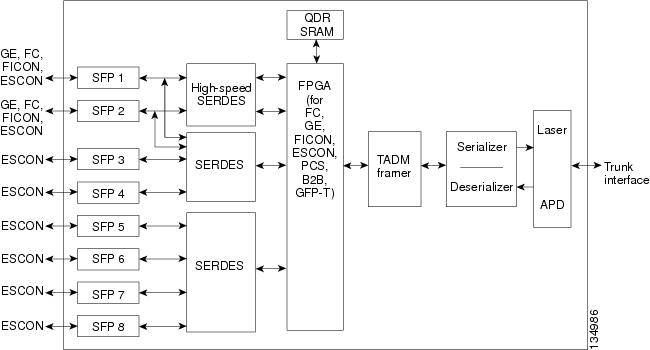
10.9.8 Automatic Laser Shutdown
The ALS procedure is supported on both client and trunk interfaces. On the client interface, ALS is compliant with ITU-T G.664 (6/99). On the data application and trunk interface, the switch on and off pulse duration is greater than 60 seconds. The on and off pulse duration is user-configurable. For details regarding ALS provisioning for the MXP_MR_2.5G and MXPP_MR_2.5G cards, refer to the Cisco ONS 15454 DWDM Procedure Guide.
10.9.9 MXP_MR_2.5G and MXPP_MR_2.5G Card-Level Indicators
Table 10-25 lists the card-level LEDs on the MXP_MR_2.5G and MXPP_MR_2.5G cards.
10.9.10 MXP_MR_2.5G and MXPP_MR_2.5G Port-Level Indicators
Table 10-26 lists the port-level LEDs on the MXP_MR_2.5G and MXPP_MR_2.5G cards.
10.10 MXP_MR_10DME_C and MXP_MR_10DME_L Cards
The MXP_MR_10DME_C and MXP_MR_10DME_L cards aggregate a mix of client SAN service client inputs (GE, FICON, and Fibre Channel) into one 10.0 Gbps STM-64/OC-192 DWDM signal on the trunk side. It provides one long-reach STM-64/OC-192 port per card and is compliant with Telcordia GR-253-CORE and ITU-T G.957.
The cards support aggregation of the following signal types:
- 1-Gigabit Fibre Channel
- 2-Gigabit Fibre Channel
- 4-Gigabit Fibre Channel
- 1-Gigabit Ethernet
- 1-Gigabit ISC-Compatible (ISC-1)
- 2-Gigabit ISC-Peer (ISC-3)
Note![]() On the card faceplates, the MXP_MR_10DME_C and MXP_MR_10DME_L cards are displayed as 10DME_C and 10DME_L, respectively.
On the card faceplates, the MXP_MR_10DME_C and MXP_MR_10DME_L cards are displayed as 10DME_C and 10DME_L, respectively.
The MXP_MR_10DME_C and MXP_MR_10DME_L muxponders pass all SONET/SDH overhead bytes transparently.
The digital wrapper function (ITU-T G.709 compliant) formats the DWDM wavelength so that it can be used to set up GCCs for data communications, enable FEC, or facilitate PM. The MXP_MR_10DME_C and MXP_MR_10DME_L cards work with the OTN devices defined in ITU-T G.709. The cards support ODU1 to OTU2 multiplexing, an industry standard method for asynchronously mapping a SONET/SDH payload into a digitally wrapped envelope. See the “Multiplexing Function” section.
Note![]() Because the client payload cannot oversubscribe the trunk, a mix of client signals can be accepted, up to a maximum limit of 10 Gbps.
Because the client payload cannot oversubscribe the trunk, a mix of client signals can be accepted, up to a maximum limit of 10 Gbps.
You can install MXP_MR_10DME_C and MXP_MR_10DME_L cards in Slots 1 to 6 and 12 to 17.
Note![]() The MXP_MR_10DME_C and MXP_MR_10DME_L cards are not compatible with the MXP_2.5G_10G card, which does not support transparent termination mode.
The MXP_MR_10DME_C and MXP_MR_10DME_L cards are not compatible with the MXP_2.5G_10G card, which does not support transparent termination mode.
The MXP_MR_10DME_C card features a tunable 1550-nm C-band laser on the trunk port. The laser is tunable across 82 wavelengths on the ITU grid with 50-GHz spacing between wavelengths. The MXP_MR_10DME_L features a tunable 1580-nm L-band laser on the trunk port. The laser is tunable across 80 wavelengths on the ITU grid, also with 50-GHz spacing. Each card features four 1310-nm lasers on the client ports and contains five transmit and receive connector pairs (labeled) on the card faceplate. The cards uses dual LC connectors on the trunk side and use SFP modules on the client side for optical cable termination. The SFP pluggable modules are SR or IR and support an LC fiber connector.
Table 10-27 shows the input data rate for each client interface, and the encapsulation method. The current version of the GFP-T G.7041 supports transparent mapping of 8B/10B block-coded protocols, including Gigabit Ethernet, Fibre Channel, ISC, and FICON.
In addition to the GFP mapping, 1-Gbps traffic on Port 1 or 2 of the high-speed SERDES is mapped to an STS-24c channel. If two 1-Gbps client signals are present at Port 1 and Port 2 of the high-speed SERDES, the Port 1 signal is mapped into the first STS-24c channel and the Port 2 signal into the second STS-24c channel. The two channels are then mapped into an OC-48 trunk channel.
|
|
|
|
|---|---|---|
There are two FPGAs on each MXP_MR_10DME_C and MXP_MR_10DME_L, and a group of four ports is mapped to each FPGA. Group 1 consists of Ports 1 through 4, and Group 2 consists of Ports 5 through 8. Table 10-28 shows some of the mix and match possibilities on the various client data rates for Ports 1 through 4, and Ports 5 through 8. An X indicates that the data rate is supported in that port.
|
|
|
|
|
|
|
|---|---|---|---|---|---|
GFP-T PM is available through RMON and trunk PM is managed according to Telcordia GR-253-CORE and ITU G.783/826. Client PM is achieved through RMON for FC and GE.
A buffer-to-buffer credit management scheme provides FC flow control. With this feature enabled, a port indicates the number of frames that can be sent to it (its buffer credit), before the sender is required to stop transmitting and wait for the receipt of a “ready” indication The MXP_MR_10DME_C and MXP_MR_10DME_L cards support FC credit-based flow control with a buffer-to-buffer credit extension of up to 1600 km (994.1 miles) for 1G FC, up to 800 km (497.1 miles) for 2G FC, or up to 400 km (248.5 miles) for 4G FC. The feature can be enabled or disabled.
The MXP_MR_10DME_C and MXP_MR_10DME_L cards feature a 1550-nm laser for the trunk/line port and a 1310-nm or 850-nm laser (depending on the SFP) for the client ports. The cards contains eight 12.5 degree downward tilt SFP modules for the client interfaces. For optical termination, each SFP uses two LC connectors, which are labeled TX and RX on the faceplate. The trunk port is a dual-LC connector with a 45 degree downward angle.
The throughput of the MXP_MR_10DME_C and MXP_MR_10DME_L cards is affected by the following parameters:
- Distance extension—If distance extension is enabled on the card, it provides more throughput but more latency. If distance extension is disabled on the card, the buffer to buffer credits on the storage switch affects the throughput; higher the buffer to buffer credits higher is the throughput.
Note![]() For each link to operate at the maximum throughput, it requires a minimum number of buffer credits to be available on the devices which the link connects to. The number of buffer credits required is a function of the distance between the storage switch extension ports and the link bandwidth, that is, 1G, 2G, or 4G. These buffer credits are provided by either the storage switch (if distance extension is disabled) or by both the storage switch and the card (if distance extension is enabled).
For each link to operate at the maximum throughput, it requires a minimum number of buffer credits to be available on the devices which the link connects to. The number of buffer credits required is a function of the distance between the storage switch extension ports and the link bandwidth, that is, 1G, 2G, or 4G. These buffer credits are provided by either the storage switch (if distance extension is disabled) or by both the storage switch and the card (if distance extension is enabled).
- Forward Error Correction (FEC)—If Enhanced FEC (E-FEC) is enabled on the trunk port of the card, the throughout is significantly reduced in comparison to standard FEC being set on the trunk port.
Note![]() If distance extension is enabled on the card, the FEC status does not usually affect the throughput of the card.
If distance extension is enabled on the card, the FEC status does not usually affect the throughput of the card.
The resultant throughput of the card is usually the combined effect of the above parameters.
10.10.1 Key Features
The MXP_MR_10DME_C and MXP_MR_10DME_L cards have the following high-level features:
- Onboard E-FEC processor: The processor supports both standard RS (specified in ITU-T G.709) and E-FEC, which allows an improved gain on trunk interfaces with a resultant extension of the transmission range on these interfaces. The E-FEC functionality increases the correction capability of the transponder to improve performance, allowing operation at a lower OSNR compared to the standard RS (237,255) correction algorithm. A new BCH algorithm implemented in E-FEC allows recovery of an input BER up to 1E-3.
- Pluggable client interface optic modules: The MXP_MR_10DME_C and MXP_MR_10DME_L cards have modular interfaces. Two types of optics modules can be plugged into the card. These include an OC-48/STM 16 SR-1 interface with a 7-km (4.3-mile) nominal range (for short range and intra-office applications) and an IR-1 interface with a range up to 40 km (24.9 miles). SR-1 is defined in Telcordia GR-253-CORE and in I-16 (ITU-T G.957). IR-1 is defined in Telcordia GR-253-CORE and in S-16-1 (ITU-T G.957).
- Y-cable protection: Supports Y-cable protection between the same card type only, on ports with the same port number and signal rate. See the “Y-Cable Protection” section for more detailed information.
- High level provisioning support: The cards are initially provisioned using Cisco TransportPlanner software. Subsequently, the card can be monitored and provisioned using CTC software.
- ALS: A safety mechanism used in the event of a fiber cut. For details regarding ALS provisioning for the MXP_MR_10DME_C and MXP_MR_10DME_L cards, refer to the Cisco ONS 15454 DWDM Procedure Guide.
- Link monitoring and management: The cards use standard OC-48 OH bytes to monitor and manage incoming interfaces. The cards pass the incoming SDH/SONET data stream and its OH bytes transparently.
- Control of layered SONET/SDH transport overhead: The cards are provisionable to terminate regenerator section overhead. This is used to eliminate forwarding of unneeded layer overhead. It can help reduce the number of alarms and help isolate faults in the network.
- Automatic timing source synchronization: The MXP_MR_10DME_C and MXP_MR_10DME_L cards normally synchronize from the TCC2/TCC2P card. If for some reason, such as maintenance or upgrade activity, the TCC2/TCC2P is not available, the cards automatically synchronize to one of the input client interface clocks.
Note![]() MXP_MR_10DME_C and MXP_MR_10DME_L cards cannot be used for line timing.
MXP_MR_10DME_C and MXP_MR_10DME_L cards cannot be used for line timing.
- Configurable squelching policy: The cards can be configured to squelch the client interface output if there is LOS at the DWDM receiver or if there is a remote fault. In the event of a remote fault, the card manages MS-AIS insertion.
- The cards are tunable across the full C band (MXP_MR_10DME_C) or full L band (MXP_MR_10DME_L), thus eliminating the need to use different versions of each card to provide tunability across specific wavelengths in a band.
- You can provision a string (port name) for each fiber channel/FICON interface on the MXP_MR_10DME_C and MXP_MR_10DME_L cards, which allows the MDS Fabric Manager to create a link association between that SAN port and a SAN port on a Cisco MDS 9000 switch.
- From Software Release 9.0, the fast switch feature of MXP_MR_10DME_C and MXP_MR_10DME_L cards along with the buffer-to-buffer credit recovery feature of MDS switches, prevents reinitialization of ISL links during Y-cable switchovers.
10.10.2 Faceplate
Figure 10-25 shows the MXP_MR_10DME_C and MXP_MR_10DME_L faceplates and block diagram.
Figure 10-25 MXP_MR_10DME_C and MXP_MR_10DME_L Faceplates and Block Diagram
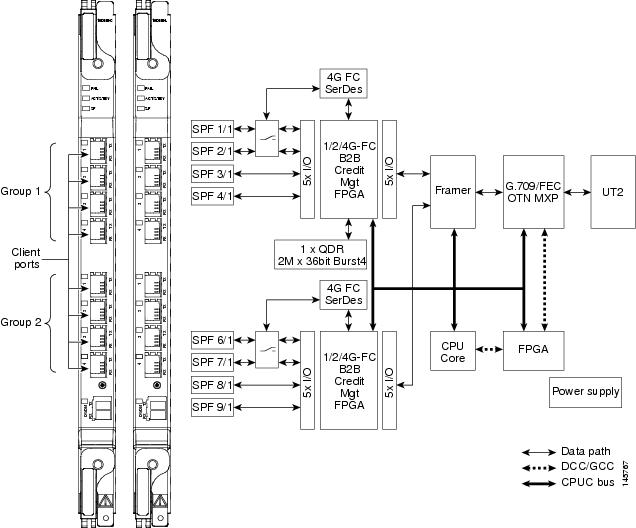
For information on safety labels for the cards, see the “Class 1M Laser Product Cards” section.
10.10.3 Wavelength Identification
The card uses trunk lasers that are wavelocked, which allows the trunk transmitter to operate on the ITU grid effectively. Both the MXP_MR_10DME_C and MXP_MR_10DME_L cards implement the UT2 module. The MXP_MR_10DME_C card uses a C-band version of the UT2 and the MXP_MR_10DME_L card uses an L-band version.
Table 10-29 describes the required trunk transmit laser wavelengths for the MXP_MR_10DME_C card. The laser is tunable over 82 wavelengths in the C band at 50-GHz spacing on the ITU grid.
|
|
|
|
|
|
|
|---|---|---|---|---|---|
Table 10-30 describes the required trunk transmit laser wavelengths for the MXP_MR_10DME_L card. The laser is fully tunable over 80 wavelengths in the L band at 50-GHz spacing on the ITU grid.
|
|
|
|
|
|
|
|---|---|---|---|---|---|
10.10.4 MXP_MR_10DME_C and MXP_MR_10DME_L Card-Level Indicators
Table 10-31 describes the three card-level LEDs on the MXP_MR_10DME_C and MXP_MR_10DME_L cards.
10.10.5 MXP_MR_10DME_C and MXP_MR_10DME_L Port-Level Indicators
Table 10-32 describes the port-level LEDs on the MXP_MR_10DME_C and MXP_MR_10DME_L cards.
10.11 GE_XP, 10GE_XP, GE_XPE, and 10GE_XPE Cards
GE_XP, 10GE_XP, GE_XPE, and 10GE_XPE cards are Gigabit Ethernet Xponders for the ONS 15454 ANSI and ETSI platforms.
Note![]() GE_XPE card is the enhanced version of the GE_XP card and 10GE_XPE card is the enhanced version of the 10GE_XP card.
GE_XPE card is the enhanced version of the GE_XP card and 10GE_XPE card is the enhanced version of the 10GE_XP card.
The cards aggregate Ethernet packets received on the client ports for transport on C-band trunk ports that operate on a 100-GHz grid. The trunk ports operate with ITU-T G.709 framing and either FEC or E-FEC. The GE_XP and 10GE_XP cards are designed for bulk point-to-point transport over 10GE LAN PHY wavelengths for Video-on-Demand (VOD), or broadcast video across protected 10GE LAN PHY wavelengths. The GE_XPE and 10GE_XPE cards are designed for bulk GE_XPE or 10GE_XPE point-to-point, point-to-multipoint, multipoint-to-multipoint transport over 10GE LAN PHY wavelengths for Video-on-Demand (VOD), or broadcast video across protected 10GE LAN PHY wavelengths.
The GE_XP, 10GE_XP, GE_XPE, and 10GE_XPE cards can be installed in Slots 1 through 6 or 12 through 17. The GE_XP and GE_XPE are double-slot cards with twenty Gigabit Ethernet client ports and two 10 Gigabit Ethernet trunk ports. The 10GE_XP and 10GE_XPE are single-slot cards with two 10 Gigabit Ethernet client ports and two 10 Gigabit Ethernet trunk ports. The client ports support SX, LX, and ZX SFPs and SR and 10GBASE-LR XFPs. (LR2 XFPs are not supported.) The trunk ports support a DWDM XFP.
GE_XP, 10GE_XP, GE_XPE, and 10GE_XPE cards can be provisioned to perform different Gigabit Ethernet transport roles. All the cards can work as Layer 2 switches. However, the 10GE_XP and 10GE_XPE cards can also perform as a 10 Gigabit Ethernet transponders (10GE TXP mode), and the GE_XP and GE_XPE can perform as a 10 Gigabit Ethernet or 20 Gigabit Ethernet muxponders (10GE MXP or 20GE MXP mode). Table 10-33 shows the card modes supported by each card.
Note![]() Changing the GE_XP, 10GE_XP, GE_XPE, or 10GE_XPE card mode requires the ports to be in a OOS-DSBL (ANSI) or Locked, disabled (ETSI) service state. In addition, no circuits can be provisioned on the cards when the mode is being changed.
Changing the GE_XP, 10GE_XP, GE_XPE, or 10GE_XPE card mode requires the ports to be in a OOS-DSBL (ANSI) or Locked, disabled (ETSI) service state. In addition, no circuits can be provisioned on the cards when the mode is being changed.
10.11.1 Key Features
The GE_XP, 10GE_XP, GE_XPE, and 10GE_XPE cards have the following high-level features:
- Gigabit Ethernet MXP, TXP, and Layer 2 switch capability over the ONS 15454 DWDM platform.
- Interoperable with TXP_MR_10E and TXP_MR_10E_C cards. Also interoperable with Cisco Catalyst 6500 and Cisco 7600 series Gigabit Ethernet and 10 Gigabit Ethernet interfaces.
Note![]() The GE_XPE and 10GE_XPE cards are interoperable with TXP_MR_10E and TXP_MR_10E_C cards. Also interoperable with Cisco Catalyst 6500 and Cisco 7600 series GE, 10GE interfaces and CRS-1 10GE Interfaces.
The GE_XPE and 10GE_XPE cards are interoperable with TXP_MR_10E and TXP_MR_10E_C cards. Also interoperable with Cisco Catalyst 6500 and Cisco 7600 series GE, 10GE interfaces and CRS-1 10GE Interfaces.
- Compatible with the ONS 15454 ANSI high-density shelf assembly, the ONS 15454 ETSI shelf assembly, and the ONS 15454 ETSI high-density shelf assembly. Compatible with TCC2 and TCC2P cards.
- Far-End Laser Control (FELC)—FELC is supported on copper SFP from Release 8.52 and later. For more information on FELC, see the “Far-End Laser Control” section.
- Ports— The GE_XP and GE_XPE cards have twenty Gigabit Ethernet client ports and two 10 Gigabit Ethernet trunk ports. The 10GE_XP and 10GE_XPE cards have two 10 Gigabit Ethernet client ports and two 10 Gigabit Ethernet trunk ports. The client Gigabit Ethernet signals are mapped into an ITU-T G.709 OTU2 signal using standard ITU-T G.709 multiplexing when configured in one of the MXP modes (10GE MXP or 20GE MXP).
- FEC and E-FEC— ITU-T G.709 framing with standard Reed-Soloman (RS) (255,237) FEC. Performance monitoring and ITU-T G.709 Optical Data Unit (ODU) synchronous and asynchronous mapping. E-FEC with ITU-T G.709 ODU and 2.7 Gbps with greater than 8 dB coding gain.
- Broadcast drop-and-continue capability for VOD and broadcast video applications.
- Layer 2 switch mode provides VLAN translation, QinQ, ingress CoS, egress QoS, Fast Ethernet protection switching, and other Layer 2 Ethernet services.
- IEEE 802.3 frame format supported for 10 Gigabit Ethernet interfaces. The minimum frame size is 64 bytes. The maximum frame size is user-provisionable.
- MAC learning capability in Layer 2 switch mode.
- MAC address retrieval in cards provisioned in the L2-over-DWDM mode.
- Configurable service provider VLANs (SVLANs) and customer VLANs (CVLANs).
- In Layer 2 switch mode, ports can be provisioned as network-to-network interfaces (NNIs) or user-network interfaces (UNIs) to facilitate service provider to customer traffic management.
- When a port is in UNI mode, tagging can be configured as transparent or selective. In transparent mode, only SVLANs in the VLAN database of the node can be configured. In selective mode, a CVLAN- to-SVLAN relationship can be defined.
- Layer 2 VLAN port mapping allows the cards to be configured as multiple Gigabit Ethernet TXPs and MXPs.
- Y-cable protection is configurable in TXP and MXP modes.
- Two protection schemes are available in Layer 2 mode. They are:
–![]() 1+1 protection—Protection scheme to address card, port, or shelf failures for client ports.
1+1 protection—Protection scheme to address card, port, or shelf failures for client ports.
–![]() Fast Automatic Protection—Protection scheme to address card, port, or shelf failures for trunk ports.
Fast Automatic Protection—Protection scheme to address card, port, or shelf failures for trunk ports.
- End-to-end Ethernet link integrity.
- Pluggable client interface optic modules (SFPs and XFPs)—Client ports support tri-rate SX, LX, and ZX SFPs, and 10-Gbps SR1 XFPs.
- Pluggable trunk interface optic modules; trunk ports support the DWDM XFP.
- Internet Group Management Protocol (IGMP) snooping to restrict the flooding of multicast traffic by forwarding multicast traffic to those interfaces where a multicast device is present.
- Multicast VLAN Registration (MVR) for applications using wide-scale deployment of multicast traffic across an Ethernet ring-based service provider network.
- Ingress CoS—Assigns a CoS value to the port from 0 (highest) to 7 (lowest) and accepts CoS of incoming frames.
- Egress QoS—Defines the QoS capabilities for the egress port.
- MAC Learning—MAC address learning to facilitate switch processing.
10.11.2 Faceplate and Block Diagram
Figure 10-26 shows the GE_XP faceplate and block diagram. The GE_XPE faceplate and block diagram looks the same.
Figure 10-26 GE_XP and GE_XPE Faceplates and Block Diagram
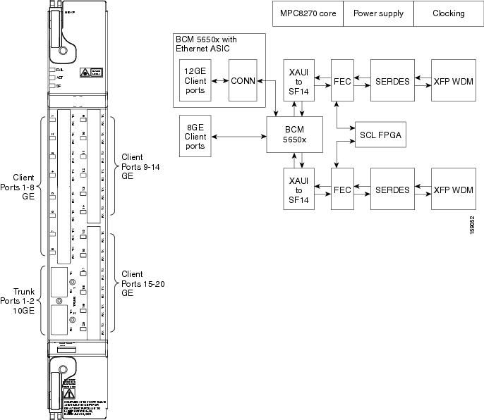
The GE_XP, 10GE_XP, GE_XPE, and 10GE_XPE cards have two trunk ports. The GE_XP and GE_XPE trunk ports are displayed as follows:
- Trunk 1 and Trunk 2 on the faceplate
- 21-1 and 22-1 on CTC
- 21 (Trunk) and 22 (Trunk) on the Optics Thresholds table
Figure 10-27 shows the 10GE_XP faceplate and block diagram. The 10 GE_XPE faceplate and block diagram looks the same.
Figure 10-27 10GE_XP and 10GE_XPE Faceplates and Block Diagram
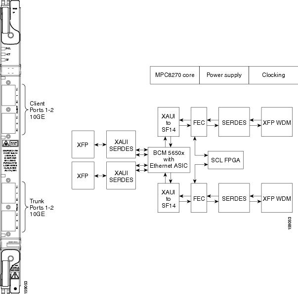
The 10GE_XP and 10GE_XPE card trunk ports are displayed as follows:
- Trunk 1 and Trunk 2 on the faceplate
- 3-1 and 4-1 on CTC
- 3 (Trunk) and 4 (Trunk) on the Optics Thresholds table
For information on safety labels for the cards, see the “Class 1M Laser Product Cards” section.
10.11.3 Client Interface
The client interface is implemented with separately orderable SFP or XFP modules. The client interfaces support the following tri-rate SFPs and XFPs using dual LC connectors and multimode fiber:
- SFP - GE/1G-FC/2G-FC - 850 nm - MM - LC (PID ONS-SE-G2F-SX)
- SFP - GE/1G-FC/2G-FC 1300 nm - SM - LC (PID ONS-SE-G2F-LX)
- SFP - GE/1G-FC/2G-FC 1300 nm - SM - LC (PID ONS-SE-G2F-ZX)
- SFP - 10/100/1000Base-T - Copper (PID ONS-SE-ZE-EL) Intra office up to 100;
Cable: RJ45 STP CAT5, CAT5E, and CAT6 - SFP - 1000Base BX D/Gigabit Ethernet 1550 nm - SM - LC (PID ONS-SE-GE-BXD)
- SFP - 1000Base BX U/Gigabit Ethernet 1550 nm - SM - LC (PID ONS-SE-GE-BXU)
- SFP - Fast Ethernet 1310 nm - SM - LC (PID ONS-SI-100-LX10)
- SFP - Fast Ethernet 1310 nm - MM - LC (PID ONS-SI-100-FX)
- SFP - Fast Ethernet over DS1/E1 - SM - LC (PID ONS-SC-EOP1)
- SFP - Fast Ethernet over DS3/E3 - SM - LC (PID ONS-SC-EOP3)
- SFP - E1/DS1 over Fast Ethernet - SM - LC (PID ONS-SC-E1-T1-PW)
The client interfaces support the following dual-rate XFP using dual LC connectors and single-mode fiber:
- XFP - OC-192/STM-64/10GE/10-FC/OTU2 - 1310 SR - SM LC (PID: ONS-XC-10G-S1)
- XFP - 10GE - 1550 nm - SM - LC (PID ONS-XC-10G-L2)
- XFP - 10GE - 1550 nm - SM - LC (PID ONS-XC-10G-C)
Note![]() If ONS-XC-10G-C XFP is used on GE_XP, 10GE_XP, GE_XPE, and 10GE_XPE cards on client port 1, the maximum temperature at which the system qualifies is +45 degree Celsius.
If ONS-XC-10G-C XFP is used on GE_XP, 10GE_XP, GE_XPE, and 10GE_XPE cards on client port 1, the maximum temperature at which the system qualifies is +45 degree Celsius.
The client interfaces support the following multimode XFP using dual LC connectors and multi-mode fiber:
Note![]() On GE_XP card, the copper Pluggable Port Module (PPM) interface can auto-negotiate and carry traffic even when the peer interface operates at rates other than 1000 Mbps.
On GE_XP card, the copper Pluggable Port Module (PPM) interface can auto-negotiate and carry traffic even when the peer interface operates at rates other than 1000 Mbps.
10.11.4 GE_XP, 10GE_XP, GE_XPE, and 10GE_XPE Card-Level Indicators
Table 10-34 describes the three card-level LEDs on the GE_XP, 10GE_XP, GE_XPE, and 10GE_XPE cards.
10.11.5 GE_XP, 10GE_XP, GE_XPE, and 10GE_XPE Port-Level Indicators
Table 10-35 describes the port-level LEDs on the GE_XP, 10GE_XP, GE_XPE, and 10GE_XPE cards.
10.11.6 DWDM Trunk Interface
The GE_XP, 10GE_XP, GE_XPE, and 10GE_XPE cards have two 10 Gigabit Ethernet trunk ports operating at 10 Gigabit Ethernet (10.3125 Gbps) or 10 Gigabit Ethernet into OTU2 (nonstandard 11.0957 Gbps). The ports are compliant with ITU-T G.707, ITU-T G.709, and Telcordia GR-253-CORE standards. The ports are capable of carrying C-band and L-band wavelengths through insertion of DWDM XFPs. Forty channels are available in the 1550-nm C band 100-GHz ITU grid, and forty channels are available in the L band.
The maximum system reach in filterless applications without the use of optical amplification or regenerators is nominally rated at 23 dB over C-SMF fiber. This rating is not a product specification, but is given for informational purposes. It is subject to change.
10.11.7 Configuration Management
The GE_XP, 10GE_XP, GE_XPE, and 10GE_XPE cards support the following configuration management parameters:
- Port name—User-assigned text string.
- Admin State/Service State—Administrative and service states to manage and view port status.
- MTU—Provisionable maximum transfer unit (MTU) to set the maximum number of bytes per frames accepted on the port.
- Mode—Provisional port mode, either Autonegotiation or the port speed.
- Flow Control—Flow control according to IEEE 802.1x pause frame specification can be enabled or disabled for TX and RX ports.
- Bandwidth—Provisionable maximum bandwidth allowed for the port.
- Ingress CoS—Assigns a CoS value to the port from 0 (highest) to 7 (lowest) and accepts CoS of incoming frames.
- Egress QoS—Defines the QoS capabilities at the egress port.
- NIM—Defines the port network interface management type based on Metro Ethernet Forum specifications. Ports can be defined as UNI or NNI.
- MAC Learning—MAC address learning to facilitate switch processing.
- VLAN tagging provided according to the IEEE 802.1Q standard.
Note![]() When the GE_XP, 10GE_XP, GE_XPE, and 10GE_XPE cards are provisioned in a MXP or TXP mode, only the following parameters are available: Port Name, State, MTU, Mode, Flow control, and Bandwidth.
When the GE_XP, 10GE_XP, GE_XPE, and 10GE_XPE cards are provisioned in a MXP or TXP mode, only the following parameters are available: Port Name, State, MTU, Mode, Flow control, and Bandwidth.
10.11.8 Security
GE_XP, 10GE_XP, GE_XPE, and 10GE_XPE card ports can be provisioned to block traffic from a user-defined set of MAC addresses. The remaining traffic is normally switched. You can manually specify the set of blocked MAC addresses for each port. Each port of the card can receive traffic from a limited predefined set of MAC addresses. The remaining traffic will be dropped. This capability is a subset of the Cisco IOS “Port Security” feature.
10.11.9 Card Protection
The following section describes various card protection schemes available for the GE_XP, 10GE_XP, GE_XPE, and 10GE_XPE cards.
10.11.9.1 1+1 Protection
1+1 protection of GE_XP, 10GE_XP, GE_XPE, and 10GE_XPE cards is provided in the Layer 2 (L2) card mode to protect against client port and card failure.
1+1 protection is supported in both single shelf and multishelf setup. This means that the working card can be in one shelf and the protect card can be in another shelf of a multishelf setup. Communication between the two cards is across 10 Gigabit Ethernet interconnection interface using Ethernet packets. The Inter link (ILK) trunk or internal pathcord must be provisioned on both the cards. This link is used to transmit protection switching messages and data. For information on how to provision ILK or internal patchcords, refer Cisco ONS 15454 DWDM Procedure Guide.
Note![]() With 1+1 protection mechanisms, the switch time of a copper SFP is 1 second.
With 1+1 protection mechanisms, the switch time of a copper SFP is 1 second.
With 1+1 protection, ports on the protect card can be assigned to protect the corresponding ports on the working card. A working card must be paired with a protect card of the same type and number of ports. The protection takes place on the port level, and any number of ports on the protect card can be assigned to protect the corresponding ports on the working card.
To make the 1+1 protection scheme fully redundant, enable L2 protection for the entire VLAN ring. This enables Fast Automatic Protection Switch (FAPS). The VLAN configured on the 1+1 port must be configured as protected SVLAN. For information on how to enable FAPS, see Cisco ONS 15454 DWDM Procedure Guide.
1+1 protection can be either revertive or nonrevertive. With nonrevertive 1+1 protection, when a failure occurs and the signal switches from the working card to the protect card, the signal remains on the protect card until it is manually changed. Revertive 1+1 protection automatically switches the signal back to the working card when the working card comes back online. 1+1 protection uses trunk ports to send control traffic between working and protect cards. This trunk port connection is known as ILK trunk ports and can be provisioned via CTC. For information on how to provision an ILK link, see “DLP-G460 Provision an ILK Link” in the Cisco ONS 15454 DWDM Procedure Guide.
The standby port can be configured to turn ON or OFF but the traffic coming to and from the standby port will be down. If the laser is ON at the standby port, the other end port (where traffic originates) will not be down in a parallel connection. Traffic is blocked on the standby port.
1+1 protection is bidirectional and nonrevertive by default; revertive switching can be provisioned using CTC. For information on how to provision the cards, refer to the Cisco ONS 15454 DWDM Procedure Guide.
10.11.9.2 Y-Cable Protection
The GE_XP and GE_XPE cards support Y-cable protection when they are provisioned in 10 Gigabit Ethernet or 20 Gigabit Ethernet MXP card mode. The 10GE_XP and 10GE_XPE cards support Y-cable protection when they are provisioned in 10GE TXP card mode. Two cards can be joined in a Y-cable protection group with one card assigned as the working card and the other defined as the protection card. This protection mechanism provides redundant bidirectional paths. See the “Y-Cable Protection” section for more detailed information. The Y-cable protection mechanism is provisionable and can be set ON or OFF (OFF is the default mode). When a signal fault is detected (LOS, LOF, SD, or SF on the DWDM receiver port in the case of ITU-T G.709 mode) the protection mechanism software automatically switches between paths. Y-cable protection also supports revertive and nonrevertive mode.
10.11.9.3 Layer 2 Over DWDM Protection
When the GE_XP, 10GE_XP, GE_XPE, or 10GE_XPE cards are in L2 over DWDM card mode, protection is handled by the hardware at the Layer 1 and Layer 2 levels. Fault detection and failure propagation is communicated through the ITU-T G.709 frame overhead bytes. For protected VLANs, traffic is flooded around the 10 Gigabit Ethernet DWDM ring. To set up the Layer 2 protection, you identify a node and the GE_XP, 10GE_XP, GE_XPE, or 10GE_XPE port that is to serve as the master node and port for the VLAN ring on the card view Provisioning > Protection tab. If a failure occurs, the node and port are responsible for opening and closing VLAN loops.
Note![]() The Forced option in the Protection drop-down list converts all the SVLANs to protected SVLANs irrespective of the SVLAN protection configuration in the SVLAN database. This is applicable to a point-to-point linear topology. The SVLAN protection must be forced to move all SVLANs, including protected and unprotected SVLANs, to the protect path irrespective of provisioned SVLAN attributes.
The Forced option in the Protection drop-down list converts all the SVLANs to protected SVLANs irrespective of the SVLAN protection configuration in the SVLAN database. This is applicable to a point-to-point linear topology. The SVLAN protection must be forced to move all SVLANs, including protected and unprotected SVLANs, to the protect path irrespective of provisioned SVLAN attributes.
A FAPS switchover happens in the following failure scenarios:
- DWDM line failures caused by a fiber cut
- Unidirectional failure in the DWDM network caused by a fiber cut
- Fiber pull on the master card trunk port followed by a hard reset on the master card
- Hard reset on the master card
- Hard reset on the slave card
- An OTN failure is detected (LOS, OTUK-LOF, OTUK-LOM, OTUK-LOM, OTUK-SF, or OTUK-BDI on the DWDM receiver port in the case of ITU-T G.709 mode)
- Trunk ports are moved to OOS,DSBLD (Locked,disabled) state
- Improper removal of XFPs
A FAPS switchover does not happen in the following scenarios:
10.11.10 IGMP Snooping
As networks increase in size, multicast routing becomes critically important as a means to determine which segments require multicast traffic and which do not. IP multicasting allows IP traffic to be propagated from one source to a number of destinations, or from many sources to many destinations. Rather than sending one packet to each destination, one packet is sent to the multicast group identified by a single IP destination group address. GE_XP, 10GE_XP, GE_XPE, and 10GE_XPE cards can learn upto a maximum of 1024 multicast groups. This includes groups on all the VLANs.
Internet Group Management Protocol (IGMP) snooping restricts the flooding of multicast traffic by forwarding multicast traffic to those interfaces where a multicast device is present.
When the GE_XP, 10GE_XP, GE_XPE, or 10GE_XPE card receives an IGMP leave group message from a host, it removes the host port from the multicast forwarding table after generating group specific queries to ensure that no other hosts interested in traffic for the particular group are present on that port. Even in the absence of any “leave” message, the cards have a timeout mechanism to update the group table with the latest information. After a card relays IGMP queries from the multicast router, it deletes entries periodically if it does not receive any IGMP membership reports from the multicast clients.
In a multicast router, general queries are sent on a VLAN when Protocol Independent Multicast (PIM) is enabled on the VLAN. The GE_XP, 10GE_XP, GE_XPE, or 10GE_XPE card forwards queries to all ports belonging to the VLAN. All hosts interested in this multicast traffic send Join requests and are added to the forwarding table entry. The Join requests are forwarded only to router ports. By default, these router ports are learned dynamically. However, they can also be statically configured at the port level in which case the static configuration overrides dynamic learning.
The GE_XP, 10GE_XP, GE_XPE, and 10GE_XPE cards support IGMP snooping V2 as specified in RFC 4541.
Note![]() The GE_XP, 10GE_XP, GE_XPE, and 10GE_XPE cards can interoperate with V1 hosts. IGMPV3 snooping is not supported and the packets are flooded in the SVLAN. Layer 2 multicast groups learned through IGMP snooping are dynamic.
The GE_XP, 10GE_XP, GE_XPE, and 10GE_XPE cards can interoperate with V1 hosts. IGMPV3 snooping is not supported and the packets are flooded in the SVLAN. Layer 2 multicast groups learned through IGMP snooping are dynamic.
GE_XP and 10GE_XP cards can support IGMP snooping on 128 stacked VLANs and GE_XPE and 10GE_XPE cards can support up to 256 stacked VLANs that are enabled. IGMP snooping can be configured on a per SVLAN basis. By default, the feature is disabled on all SVLANs.
Note![]() When IGMP snooping is enabled on double-tagged packets, CVLAN has to be the same on all ports attached to the same SVLAN.
When IGMP snooping is enabled on double-tagged packets, CVLAN has to be the same on all ports attached to the same SVLAN.
Note![]() When IGMP snooping is working with Fast Automatic Protection Switch (FAPS) in a ring based setup, it is advisable to configure all NNI ports as static router ports. This minimizes the multicast traffic hit when a FAPS switchover occurs.
When IGMP snooping is working with Fast Automatic Protection Switch (FAPS) in a ring based setup, it is advisable to configure all NNI ports as static router ports. This minimizes the multicast traffic hit when a FAPS switchover occurs.
The following conditions are raised from IGMP snooping at the card:
- MCAST-MAC-TABLE-FULL—This condition is raised when the multicast table is full and a new join request is received. This table is cleared when at least one entry gets cleared from the multicast table after the alarm is raised.
- MCAST-MAC-ALIASING—This condition is raised when there are multiple L3 addresses that map to the same L2 address in a VLAN. This is a transient condition.
For more information on severity level of these conditions and procedure to clear these alarms, refer to the Cisco ONS 15454 Troubleshooting Guide.
10.11.10.1 Fast-Leave Processing
Note![]() Fast-Leave processing is also known as Immediate-Leave.
Fast-Leave processing is also known as Immediate-Leave.
IGMP snooping Fast-Leave processing allows the GE_XP, 10GE_XP, GE_XPE, or 10GE_XPE to remove an interface that sends a leave message from the forwarding table without first sending group specific queries to the interface. When you enable IGMP Fast-Leave processing, the card immediately removes a port from the IP multicast group when it detects an IGMP, version 2 (IGMPv2) leave message on that port.
10.11.10.2 Static Router Port Configuration
Multicast-capable ports are added to the forwarding table for every IP multicast entry. The card learns of such ports through the PIM method.
10.11.10.3 Report Suppression
Report suppression is used to avoid a storm of responses to an IGMP query. When this feature is enabled, a single IGMP report is sent to each multicast group in response to a single query. Whenever an IGMP snooping report is received, report suppression happens if the report suppression timer is running. The Report suppression timer is started when the first report is received for a general query. Then this time is set to the response time specified in general query.
10.11.10.4 IGMP Statistics and Counters
An entry in a counter contains multicasting statistical information for the IGMP snooping capable GE_XP, 10GE_XP, GE_XPE, or 10GE_XPE card. It provides statistical information about IGMP messages that have been transmitted and received. IGMP statistics and counters can be viewed via CTC from the Performance > Ether Ports > Statistics tab.
This information can be stored in the following counters:
- cisTxGeneralQueries—Number of general queries transmitted through an interface.
- cisTxGroupSpecificQueries—Total group specific queries transmitted through an interface.
- cisTxReports—Total membership reports transmitted through an interface.
- cisTxLeaves—Total Leave messages transmitted through an interface.
- cisRxGeneralQueries—Total general queries received at an interface.
- cisRxGroupSpecificQueries—Total Group Specific Queries received at an interface.
- cisRxReports—Total Membership Reports received at an interface.
- cisRxLeaves—Total Leave messages received at an interface.
- cisRxValidPackets—Total valid IGMP packets received at an interface.
- cisRxInvalidPackets—Total number of packets that are not valid IGMP messages received at an interface.
10.11.11 Multicast VLAN Registration
Multicast VLAN Registration (MVR) is designed for applications using wide-scale deployment of multicast traffic across an Ethernet-ring-based service provider network (for example, the broadcast of multiple television channels over a service-provider network). MVR allows a subscriber on a port to subscribe and unsubscribe to a multicast stream on the network-wide multicast VLAN. It allows the single multicast VLAN to be shared in the network while subscribers remain in separate VLANs. MVR provides the ability to continuously send multicast streams in the multicast VLAN, but to isolate the streams from the subscriber VLANs for bandwidth and security reasons.
MVR assumes that subscriber ports subscribe and unsubscribe (“Join” and “Leave”) these multicast streams by sending out IGMP Join and Leave messages. These messages can originate from an IGMP version-2-compatible host with an Ethernet connection. MVR operates on the underlying mechanism of IGMP snooping. MVR works only when IGMP snooping is enabled.
The card identifies the MVR IP multicast streams and their associated MAC addresses in the card forwarding table, intercepts the IGMP messages, and modifies the forwarding table to include or remove the subscriber as a receiver of the multicast stream, even though the receivers is in a different VLAN than the source. This forwarding behavior selectively allows traffic to cross between different VLANs.
Note![]() When MVR is configured, the port facing the router must be configured as NNI in order to allow the router to generate or send multicast stream to the host with the SVLAN. If router port is configured as UNI, the MVR will not work properly.
When MVR is configured, the port facing the router must be configured as NNI in order to allow the router to generate or send multicast stream to the host with the SVLAN. If router port is configured as UNI, the MVR will not work properly.
10.11.12 MAC Address Learning
The GE_XPE and 10 GE_XPE cards support 32K MAC addresses. MAC address learning can be enabled or disabled per SVLAN on GE_XPE and 10 GE_XPE cards. The cards learn the MAC address of packets they receive on each port and add the MAC address and its associated port number to the MAC address learning table. As stations are added or removed from the network, the GE_XPE and 10 GE_XPE cards update the MAC address learning table, adding new dynamic addresses and aging out those that are currently not in use.
MAC address learning can be enabled or disabled per SVLAN. When the configuration is changed from enable to disable, all the related MAC addresses are cleared. The following conditions apply:
- If MAC address learning is enabled on per port basis, the MAC address learning is not enabled on all VLANs, but only on VLANs that have MAC address learning enabled.
- If per port MAC address learning is disabled then the MAC address learning is disabled on all VLANs, even if it is enabled on some of the VLAN supported by the port.
- If the per port MAC address learning is configured on GE-XP and 10 GE-XP cards, before upgrading to GE-XPE or 10 GE-XPE cards, enable MAC address learning per SVLAN. Failing to do so disables MAC address learning.
10.11.13 MAC Address Retrieval
MAC addresses learned can be retrieved or cleared on GE_XP, 10GE_XP, GE_XPE, and 10GE_XPE cards provisioned in L2-over-DWDM mode. The MAC addresses can be retrieved using the CTC or TL1 interface.
GE_XPE and 10GE_XPE cards support 32K MAC addresses and GE_XP and 10GE_XP cards support 16K MAC addresses. To avoid delay in processing requests, the learned MAC addresses are retrieved using an SVLAN range. The valid SVLAN range is from 1 to 4093.
The MAC addresses of the GE_XP, 10GE_XP, GE_XPE, and 10GE_XPE cards can also be retrieved. The card MAC addresses are static and are used for troubleshooting activities. One MAC address is assigned to each client, trunk, and CPU ports of the GE_XP, 10GE_XP, GE_XPE, or 10GE_XPE card. These internal MAC addresses can be used to determine if the packets received on the far-end node are generated by GE_XP, 10GE_XP, GE_XPE, and 10GE_XPE cards.
For MAC address retrieval, the following conditions apply:
- The cards must be provisioned in L2-over-DWDM mode.
- MAC address learning must be enabled per SVLAN on GE_XPE or 10 GE_XPE cards.
- MAC address learning must be enabled per port on GE_XP or 10 GE_XP cards.
For information on how to retrieve or clear MAC addresses learned, refer to the “Provision Transponder and Muxponder Cards” chapter in the Cisco ONS 15454 DWDM Procedure Guide.
10.11.14 Link Integrity
The GE_XP, 10GE_XP, GE_XPE, and 10GE_XPE card support end-to-end Ethernet link integrity. This capability is integral to providing an Ethernet private line service and correct operation of Layer 2 and Layer 3 protocols on the attached Ethernet devices.
The link integrity feature propagates a trunk fault on all the affected SVLAN circuits in order to squelch the far end client interface. Ethernet-Advanced IP Services (E-AIS) packets are generated on a per-port/SVLAN basis. An E-AIS format is compliant with ITU Y.1731.
Note![]() E-AIS packets are marked with a CoS value of 7 (also called.1p bits). Ensure that the network is not overloaded and there is sufficient bandwidth for this queue in order to avoid packet drops.
E-AIS packets are marked with a CoS value of 7 (also called.1p bits). Ensure that the network is not overloaded and there is sufficient bandwidth for this queue in order to avoid packet drops.
When link integrity is enabled on a per-port SVLAN basis, E-AIS packets are generated when the following alarms are raised;
When link integrity is enabled, GE_XP and 10 GE_XP card supports up to128 SVLANs and GE_XPE, 10 GE_XPE can support up to 256 SVLANs.
10.11.15 Ingress CoS
Ingress CoS functionality enables differentiated services across the GE_XPE and 10GE_XPE cards. A wide range of networking requirements can be provisioned by specifying the class of service applicable to each transmitted traffic.
When a CVLAN is configured as ingress CoS, the per-sport settings are not considered. A maximum of 128 CVLAN and CoS relationships can be configured.
10.12 ADM-10G Card
The ADM-10G card operates on ONS 15454 SONET, ONS 15454 SDH, and DWDM networks to carry optical signals and Gigabit Ethernet signals over DWDM wavelengths for transport. The card aggregates lower bit-rate client SONET or SDH signals (OC-3/STM-1, OC-12/STM-4, OC-48/STM-16, or Gigabit Ethernet) onto a C-band tunable DWDM trunk operating at a higher OC-192/STM-64 rate. In a DWDM network, the ADM-10G card transports traffic over DWDM by mapping Gigabit Ethernet and SONET or SDH circuits onto the same wavelength with multiple protection options.
The ADM-10G card is a double-slot card that can be installed in Slots 1 through 5 or 12 through 16 in standard and high-density ONS 15454 ANSI shelves (15454-SA-ANSI or 15454-SA-HD), the ETSI ONS 15454 standard shelf assembly, or the ONS 15454 ETSI high-density shelf assembly. Installation is supported in any of these slots.
Note![]() The recommended slots are 1, 3, 5 and 12, 14, 16.
The recommended slots are 1, 3, 5 and 12, 14, 16.
The card is compliant with ITU-T G.825 and ITU-T G.783 for SDH signals. It supports concatenated and nonconcatenated AU-4 mapped STM-1, STM-4, and STM-16 signals as specified in ITU-T G.707. The card also complies with Section 5.6 of Telcordia GR-253-CORE and supports synchronous transport signal (STS) mapped OC-3, OC-12, and OC-48 signals as specified in the standard.
The client SFP and trunk XFP are compliant with interface requirements in Telcordia GR-253-CORE, ITU-T G.957 and/or ITU-T G.959.1, and IEEE 802.3.
10.12.1 Key Features
The ADM-10G card has the following high-level features:
- Operates with the TCC2 or TCC2P.
- Interoperable with TXP_MR_10E and TXP_MR_10E_C cards.
- Has built-in OC-192/STM-64 add/drop multiplexing function including client, trunk, and STS cross-connect.
- Supports both single-card and double-card (ADM-10G peer group) configuration.
- Supports path protection/SNCP on client and trunk ports for both single-card and double-card configuration. The card does not support path protection/SNCP between a client port and a trunk port. Path protection/SNCP is supported only between two client ports or two trunk ports.
- Supports 1+1 protection on client ports for double-card configuration only.
- Supports SONET, SDH, and Gigabit Ethernet protocols on client SFPs.
- Supports XFP DWDM trunk interface single wavelengths.
- Returns zero bit errors when a TCC2 or TCC2P card switches from active to standby or when manual or forced protection switches occur.
- Has 16 SFP-based client interfaces (gray, colored, and coarse wavelength division multiplexing (CWDM) optics available).
- Supports STM1, STM4, STM16, and Gigabit Ethernet client signals (8 Gigabit Ethernet maximum).
- Has one XFP-based trunk interface supporting E-FEC/FEC and ITU-T G.709 for double-card configuration.
- Has two SR XFP interlink interfaces supporting redundancy connection with protection board and pass-through traffic for double-card configuration.
- Supports frame-mapped generic framing procedure (GFP-F) mapping for Ethernet over SONET or SDH.
- Can be installed or pulled from operation, in any slot, without impacting other service cards in the shelf.
- Supports client to client hairpinning, that is, creation of circuits between two client ports for both single-card and double-card configuration. See the “Circuit Provisioning” section for more detailed information.
10.12.2 GFP Interoperability
The ADM-10G card defaults to GFP-F encapsulation that is compliant with ITU-T G.7041. This mode allows the card to operate with ONS 15310-CL, ONS 15310-MA, ONS 15310-MA SDH, or ONS 15454 data cards (for example, ONS 15454 CE100T-8 or ML1000-2 cards). GFP encapsulation also allows the ADM-10G card to interoperate with other vendors’ Gigabit Ethernet interfaces that adhere to the ITU-T G.7041 standard.
10.12.3 Faceplate
Figure 10-28 shows the ADM-10G card faceplate.
Figure 10-28 ADM-10G Card Faceplate and Block Diagram
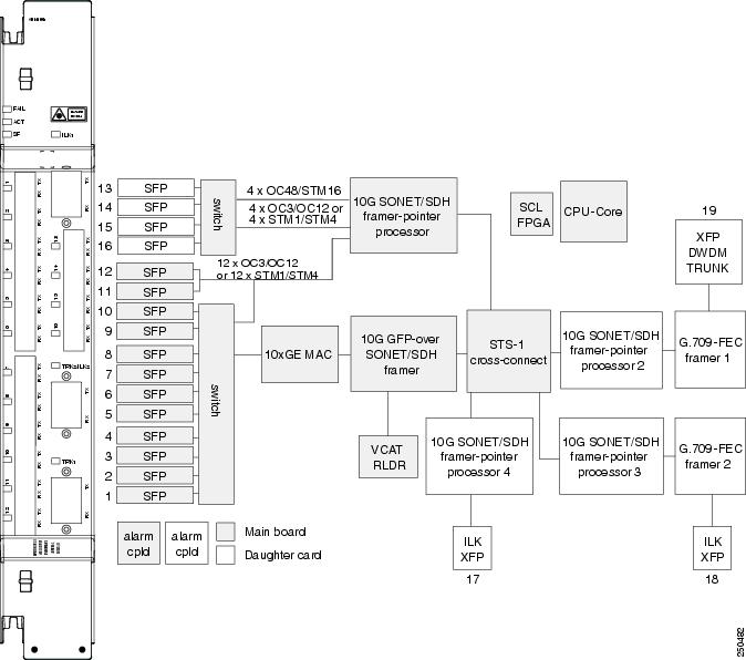
10.12.4 Port Configuration Rules
ADM-10G card client and trunk port capacities are shown in Figure 10-29.
Figure 10-29 ADM-10G Card Port Capacities
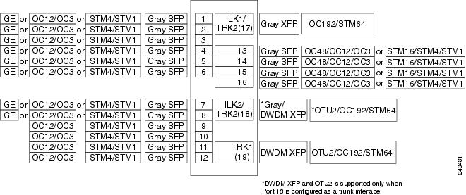
Port 17 acts as trunk2 or ILK1 interface based on single-card or double-card configuration.
10.12.5 Client Interfaces
The ADM-10G card uses LC optical port connectors and, as shown in Figure 10-29, supports up to 16 SFPs that can be utilized for OC-N/STM-N traffic. Eight of the SFPs can be used for Gigabit Ethernet. The interfaces can support any mix of OC-3/STM-1, OC-12/STM-4, OC-48/STM-16, or Gigabit Ethernet of any reach, such as SX, LX, ZX, SR, IR, or LR. The interfaces support a capacity of:
The supported client SFPs and XFPs are:
–![]() 1000Base-SX SFP 850 nm (ONS-SE-G2F-SX=)
1000Base-SX SFP 850 nm (ONS-SE-G2F-SX=)
–![]() 1000Base-LX SFP 1310 nm (ONS-SE-G2F-LX=)
1000Base-LX SFP 1310 nm (ONS-SE-G2F-LX=)
–![]() OC48/STM16 IR1, OC12/STM4 SR1, OC3/STM1 SR1, GE-LX multirate SFP 1310 nm (ONS-SE-Z1=)
OC48/STM16 IR1, OC12/STM4 SR1, OC3/STM1 SR1, GE-LX multirate SFP 1310 nm (ONS-SE-Z1=)
–![]() OC3/STM1 IR1, OC12/STM4 IR1 multirate SFP 1310 nm (ONS-SI-622-I1=)
OC3/STM1 IR1, OC12/STM4 IR1 multirate SFP 1310 nm (ONS-SI-622-I1=)
–![]() OC48/STM16 SR1 SFP 1310 nm (ONS-SI-2G-S1=)
OC48/STM16 SR1 SFP 1310 nm (ONS-SI-2G-S1=)
–![]() OC48/STM16 IR1 SFP 1310 nm (ONS-SI-2G-I1=)
OC48/STM16 IR1 SFP 1310 nm (ONS-SI-2G-I1=)
–![]() OC48/STM16, 1550 LR2, SM LC (ONS-SE-2G-L2=)
OC48/STM16, 1550 LR2, SM LC (ONS-SE-2G-L2=)
–![]() 1000Base-ZX SFP 1550 nm (ONS-SI-GE-ZX=)
1000Base-ZX SFP 1550 nm (ONS-SI-GE-ZX=)
–![]() OC3/STM1 LR2 SFP 1550 nm (ONS-SI-155-L2=)
OC3/STM1 LR2 SFP 1550 nm (ONS-SI-155-L2=)
–![]() OC48/STM16 LR2 SFP 1550 nm (ONS-SI-2G-L2=)
OC48/STM16 LR2 SFP 1550 nm (ONS-SI-2G-L2=)
–![]() OC48/STM16 SFP (ONS-SC-2G-xx.x)
OC48/STM16 SFP (ONS-SC-2G-xx.x)
Note![]() xx.x = 28.7 to 60.6. ONS-SC-2G-28.7, ONS-SC-2G-33.4, ONS-SC-2G-41.3, ONS-SC-2G-49.3, and ONS-SC-2G-57.3 are supported from Release 8.5 and later.
xx.x = 28.7 to 60.6. ONS-SC-2G-28.7, ONS-SC-2G-33.4, ONS-SC-2G-41.3, ONS-SC-2G-49.3, and ONS-SC-2G-57.3 are supported from Release 8.5 and later.
10.12.6 Interlink Interfaces
Two 2R interlink interfaces, called ILK1 (Port 17) and ILK2 (Port 18), are provided for creation of ADM-10G peer groups in double-card configurations. In a single-card configuration, Port 17 (OC-192/STM-64) and Port 18 (OC-192/STM-64 or OTU2 payload) must be configured as trunk interfaces. In a double-card configuration (ADM-10G peer group), Ports 17 and 18 must be configured as ILK1 and ILK2 interfaces, respectively. Physically cabling these ports between two ADM-10G cards, located on the same shelf, allows you to configure them as an ADM-10G peer group.The ILK ports carry 10 Gb of traffic each.
The interlink interfaces support STM64 SR1 (ONS-XC-10G-S1=) XFP and 10GE BASE SR (ONS-XC-10G-SR-MM=) XFPs.
10.12.7 DWDM Trunk Interface
The ADM-10G card supports OC-192/STM-64 signal transport and ITU-T G.709 digital wrapping according to the ITU-T G.709 standard.The ADM-10G card supports three trunk XFPs:
10.12.8 Configuration Management
When using OC-48/STM-16 traffic, some contiguous port configurations, listed in Table 10-36, are unavailable due to hardware limitations. This limitation does not impact the Gigabit Ethernet payload.
Note![]() The ADM-10G card cannot be used in the same shelf with SONET or SDH cross-connect cards.
The ADM-10G card cannot be used in the same shelf with SONET or SDH cross-connect cards.
|
|
|
|---|---|
Note![]() The total traffic rate for each trunk cannot exceed OC-192/STM-64 on each ADM-10G card, or for each ADM-10G peer group.
The total traffic rate for each trunk cannot exceed OC-192/STM-64 on each ADM-10G card, or for each ADM-10G peer group.
Note![]() Gigabit Ethernet is supported on Ports 1 through 8. Port 11 and Port 12 support only OC-3/STM-1 or OC-12/STM-4.
Gigabit Ethernet is supported on Ports 1 through 8. Port 11 and Port 12 support only OC-3/STM-1 or OC-12/STM-4.
Additionally, the following guidelines apply to the ADM-10G card:
- Trunk Port 17 supports OC-192/STM-64.
- Trunk Ports 18 and 19 support OC-192/STM-64 and OTU2.
- The interlink port supports OC-192/STM-64.
- Up to six ADM-10G cards can be installed in one shelf.
- Up to 24 ADM-10G cards can be installed per network element (NE) regardless of whether the card is installed in one shelf or in multiple shelves.
- The card can be used in all 15454-SA-ANSI and 15454-SA-HD shelves as well as ETSI ONS 15454 standard and high-density shelves.
- A lamp test function can be activated from CTC to ensure that all LEDs are functional.
- The card can operate as a working protected or working nonprotected card.
- In a redundant configuration, an active card hardware or software failure triggers a switch to the standby card. This switch is detected within 10 ms and is completed within 50 ms.
- ADM-10G cards support jumbo frames with MTU sizes of 64 to 10,000 bytes; the maximum is 9,216.
- After receiving a link or path failure, the ADM-10G card can shut down only the downstream Gigabit Ethernet port.
Note![]() In ADM-10G cards, the Gigabit Ethernet port does not support flow control.
In ADM-10G cards, the Gigabit Ethernet port does not support flow control.
10.12.9 Security
The ADM-10G card that an SFP or XFP is plugged into implements the Cisco Standard Security Code Check Algorithm that keys on the vendor ID and serial number.
If a pluggable port module (PPM) is plugged into a port on the card but fails the security code check because it is not a Cisco PPM, a minor NON-CISCO-PPM alarm is raised.
If a PPM with a nonqualified product ID is plugged into a port on this card—that is, the PPM passes the security code as a Cisco PPM but it has not been qualified for use on the ADM-10G card— a minor UNQUAL-PPM alarm is raised.
10.12.10 Protection
The ADM-10G card supports 1+1 and SONET path protection and SDH SNCP protection architectures in compliance with Telcordia GR-253-CORE, Telcordia GR-1400-CORE, and ITU-T G.841 specifications.
10.12.10.1 Circuit Protection Schemes
The ADM-10G card supports path protection/SNCP circuits at the STS/VC4 (high order) level and can be configured to switch based on signal degrade calculations. The card supports path protection/SNCP on client and trunk ports for both single-card and double-card configuration.
Note![]() The ADM-10G card supports path protection/SNCP between client ports and trunk Port 17. The card does not support path protection/SNCP between client ports and trunk ports 18 and19. The card does not support path protection/SNCP between port 17 and trunk ports 18 and 19.
The ADM-10G card supports path protection/SNCP between client ports and trunk Port 17. The card does not support path protection/SNCP between client ports and trunk ports 18 and19. The card does not support path protection/SNCP between port 17 and trunk ports 18 and 19.
The card allows open-ended path protection/SNCP configurations incorporating other vendor equipment. In an open-ended path protection/SNCP, you can specify one source point and two possible endpoints (or two possible source points and one endpoint) and the legs can include other vendor equipment. The source and endpoints are part of the network discovered by CTC.
For detailed information about path protection configurations and SNCPs, refer to the Cisco ONS 15454 Reference Manual.
10.12.10.2 Port Protection Schemes
The ADM-10G card supports 1+1 protection on client ports for double-card configuration (ADM-10G peer group) only. The card does not support 1+1 protection in single-card configuration. For 1+1 optical client port protection, you can configure the system to use any pair of like facility interfaces that are on different cards of the ADM-10G peer group. The 1+1 protection scheme can also work in a unidirectional (unprotected) way or a bidirectional (protected) way. For information on optical port protection, refer to the Cisco ONS 15454 Reference Manual.
10.12.11 Circuit Provisioning
The ADM-10G card supports STS circuit provisioning both in single-card and double-card (ADM-10G peer group) configuration. The card allows you to create STS circuits between:
Note![]() Circuits between two trunk ports are called pass-through circuits.
Circuits between two trunk ports are called pass-through circuits.
For an ADM-10G card in single-card configuration, if you are creating STS circuits between two client ports, the following limitation must be considered:
For an ADM-10G card that is part of an ADM-10G peer group, if you are creating STS circuits between two client ports or between client and trunk ports, the following limitations must be considered:
- Gigabit Ethernet to Gigabit Ethernet connections are not supported.
- Optical channel (OC) to OC, OC to Gigabit Ethernet, and Gigabit Ethernet to OC connections between two peer group cards are supported. Peer group connections use interlink port bandwidth, hence, depending on the availability/fragmentation of the interlink port bandwidth, it may not be possible to create an STS circuit from the Gigabit Ethernet/OC client port to the peer card trunk port. This is because, contiguous STSs (that is, STS-3c, STS-12c, STS-24c, and so on) must be available on the interlink port for circuit creation.
Note![]() There are no limitations to create an STS circuit between two trunk ports.
There are no limitations to create an STS circuit between two trunk ports.
The two ADM-10G cards used in a paired mode use interlink ports ILK1 (Port 17) and ILK2 (Port 18). A CCAT or VCAT circuit created between the peer ADM-10G cards uses the ILK1 port if the source or destination is Port 19. The circuits created with a single ADM-10G card uses the ILK2 port.
If the circuit is of type STS- n c (where n is an integer and can take values 3,6,9,12,18,24,36,48,96) and uses the ILK2 port, then the starting timeslot needs to use specific timeslots for traffic to flow. The timeslots can be 12 m +1 for STS-12c circuits and 48 m +1 (where m is an integer and can take values 0,1,2,3...) for STS-48c circuits. The timeslots can be 3 m +1 for the other STS- n c circuits.
The following example illustrates how to use the correct timeslot for an ILK2 port:
If there is no circuit on the ILK2 port and a STS-3c circuit is created, the circuit uses timeslots 1 to 3. An STS-12c circuit must be created on the ILK2 port later. The STS-12c circuit must have used timeslots 4 to 15. However, the STS-12c circuit uses timeslots starting from 12m+1 (1, 13, 25, and so on) as defined in the above rule. Therefore, before creating the STS-12c circuit, dummy circuits must be created in CTC that consumes STS-9 bandwidth.
10.12.12 Automatic Laser Shutdown
The ALS procedure is supported on both client and trunk interfaces. On the client interface, ALS is compliant with ITU-T G.664 (6/99). On the data application and trunk interface, the switch on and off pulse duration is greater than 60 seconds. The on and off pulse duration is user-configurable. For details on ALS provisioning for the card, refer to the Cisco ONS 15454 DWDM Procedure Guide.
10.12.13 ADM-10G Card-Level Indicators
Table 10-37 describes the card-level LEDs on the ADM-10G card.
10.12.14 ADM-10G Card Port-Level Indicators
Table 10-38 describes the port-level LEDs on the ADM-10G card.
Note![]() Client or trunk ports can each be in active or standby mode as defined in the related section for each specific protection type. For example, fiber-switched protection has active or standby trunk ports; 1+1 APS protection has active or standby client ports, and client 1+1 protection does not utilize active or standby ports.
Client or trunk ports can each be in active or standby mode as defined in the related section for each specific protection type. For example, fiber-switched protection has active or standby trunk ports; 1+1 APS protection has active or standby client ports, and client 1+1 protection does not utilize active or standby ports.
|
|
|
|---|---|
10.13 OTU2_XP Card
The OTU2_XP card is a single-slot card with four ports with XFP-based multirate (OC-192/STM-64, 10GE, 10G FC) Xponder for the ONS 15454 ANSI and ETSI platforms. The OTU2_XP card supports multiple configurations.
Table 10-39 describes the different configurations supported by the OTU2_XP card and the ports that must be used for these configurations.
|
|
|
|
|
|
|---|---|---|---|---|
2 x 10G standard regenerator (with enhanced FEC (E-FEC) only on one port) |
||||
Client port in transponder or trunk port in regenerator configuration |
||||
All the four ports are ITU-T G.709 compliant and support 40 channels (wavelengths) at 100-GHz channel spacing in the C-band (that is, the 1530.33 nm to 1561.42 nm wavelength range).
The OTU2_XP card can be installed in Slots 1 through 6 or 12 through 17. The OTU2_XP card supports SONET SR1, IR2, and LR2 XFPs, 10GE BASE SR, SW, LR, LW, ER, EW, and ZR XFPs, and 10G FC MX-SN-I and SM-LL-L XFPs.
10.13.1 Key Features
The OTU2_XP card has the following high-level features:
- 10G transponder, regenerator, and splitter protection capability on the ONS 15454 DWDM platform.
- Compatible with the ONS 15454 ANSI high-density shelf assembly, the ETSI ONS 15454 shelf assembly, and the ETSI ONS 15454 high-density shelf assembly. Compatible with TCC2 and TCC2P cards.
- Interoperable with TXP_MR_10E and TXP_MR_10E_C cards.
- Four port, multirate (OC-192/STM-64, 10G Ethernet WAN Phy, 10G Ethernet LAN Phy, 10G Fibre Channel) client interface. The client signals are mapped into an ITU-T G.709 OTU2 signal using standard ITU-T G.709 multiplexing.
- ITU-T G.709 framing with standard Reed-Soloman (RS) (255,237) FEC. Performance monitoring and ITU-T G.709 Optical Data Unit (ODU) synchronous mapping. Enhanced FEC (E-FEC) with ITU-T G.709 ODU with greater than 8 dB coding gain.
- IEEE 802.3 frame format supported for 10 Gigabit Ethernet interfaces. The minimum frame size is 64 bytes. The maximum frame size is user-provisionable.
- Supports fixed/no fixed stuff mapping (insertion of stuffing bytes) for 10G Ethernet LAN Phy signals (only in transponder configuration).
- Supports 10G Ethernet LAN Phy to 10G Ethernet WAN Phy conversion on Ports 1 (client port) and 3 (trunk port).
- Supports 10G Ethernet LAN Phy to WAN Phy conversion using CTC and TL1. When enabled on the OTU2_XP card, the first Channel (Ports 1 and 3) supports LAN to WAN conversion. The second channel carries normal 10GE, 10G FC, and OC192/STM64 traffic.
- The LAN Phy to WAN Phy conversion functions in accordance to WAN Interface Sublayer (WIS) mechanism as defined by IEEE802.3ae (IEEE Std 802.3ae-2002, Amendment to CSMA/CD).
- Default configuration is transponder, with trunk ports configured as ITU-T G.709 standard FEC.
- In transponder or regenerator configuration, if one of the ports is configured the corresponding port is automatically created.
- In regenerator configuration, only Ports 3 and 4 can be configured as E-FEC. Ports 1 and 2 can be configured only with standard FEC.
- When port pair 1-3 or 2-4 is configured as regenerator (that is, card mode is standard regenerator), the default configuration on Ports 3 and 4 is automatically set to standard FEC.
- When Ports 3 and 4 are configured as regenerator (that is, card mode is E-FEC regenerator), the default configuration on both these ports is automatically set to E-FEC.
- In splitter protected transponder configuration, the trunk ports (Ports 3 and 4) are configured as ITU-T G.709 standard FECor E-FEC.
- Supports protection through Y-cable protection scheme.
Note![]() When enabled, the 10G Ethernet LAN Phy to WAN Phy conversion feature does not support Y-cable protection on the LAN to WAN interface (ports 1 and 3).
When enabled, the 10G Ethernet LAN Phy to WAN Phy conversion feature does not support Y-cable protection on the LAN to WAN interface (ports 1 and 3).
- Client ports support SONET SR1, IR2, and LR2 XFPs, 10GE BASE SR, SW, LR, LW, ER, EW, and ZR XFPs, and 10G FC MX-SN-I and SM-LL-L XFPs.
- The MTU setting is used to display the ifInerrors and OverSizePkts counters on the receiving trunk and client port interfaces. Traffic of frame sizes up to 65535 bytes pass without any packet drops, from the client port to the trunk port and vice versa irrespective of the MTU setting.
10.13.2 Faceplate and Block Diagram
Figure 10-30 shows the OTU2_XP card faceplate and block diagram.
Figure 10-30 OTU2_XP Card Faceplate and Block Diagram
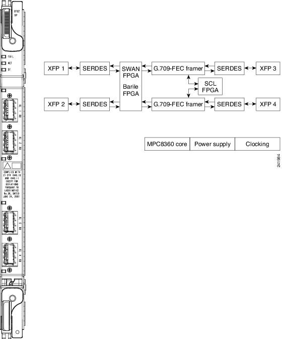
Note![]() The Swan FPGA is automatically loaded when the LAN Phy to WAN Phy conversion feature is enabled on the OTU2_XP card. The Barile FPGA is automatically loaded when the LAN Phy to WAN Phy conversion feature is disabled on the OTU2_XP card.
The Swan FPGA is automatically loaded when the LAN Phy to WAN Phy conversion feature is enabled on the OTU2_XP card. The Barile FPGA is automatically loaded when the LAN Phy to WAN Phy conversion feature is disabled on the OTU2_XP card.
10.13.3 OTU2_XP Card-Level Indicators
Table 10-40 describes the card-level LEDs on the OTU2_XP card.
10.13.4 OTU2_XP Port-Level Indicators
Table 10-41 describes the PPM port-level LEDs on the OTU2_XP card for both client and trunk ports.
Note![]() Client or trunk ports can each be in active or standby mode as defined in the related section for each specific protection type. For example, fiber-switched protection has active or standby trunk ports; 1+1 APS protection has active or standby client ports, and client 1+1 protection does not utilize active or standby ports.
Client or trunk ports can each be in active or standby mode as defined in the related section for each specific protection type. For example, fiber-switched protection has active or standby trunk ports; 1+1 APS protection has active or standby client ports, and client 1+1 protection does not utilize active or standby ports.
|
|
|
|---|---|
10.13.5 OTU2_XP Card Interface
The OTU2_XP card is a multi-functional card that operates in different configurations, such as transponder, standard regenerator, E-FEC regenerator, and 10G Ethernet LAN Phy to WAN Phy conversion mode. The OTU2_XP card acts as a protected transponder, when the 10G Ethernet LAN Phy to WAN Phy is in splitter protected transponder configuration mode.
Depending on the configuration of the OTU2_XP card, the ports act as client or trunk ports (see Table 10-39 ). This following section describes the client and trunk rates supported on the OTU2_XP card for different card configurations:
10.13.5.1 Client Interface
In transponder and 10G Ethernet LAN Phy to WAN Phy card configurations, Ports 1 and 2 act as client ports and in splitter protected transponder configuration, Port 1 acts as a client port. For these card configurations, the client rates supported are:
10.13.5.2 Trunk Interface
In transponder, 10G Ethernet LAN Phy to WAN Phy, and splitter protected transponder card configurations, Ports 3 and 4 act as trunk ports. For these card configurations, the trunk rates supported are:
- OC-192/STM-64
- 10G Ethernet WAN Phy
- 10G Ethernet LAN Phy
- 10G Fibre Channel
- OTU2 with ITU-T G.709 for OC-192 client interface
- OTU2e with ITU-T G.709 for 10G Ethernet LAN Phy client interface
In standard regenerator card configuration, all four ports act as trunk ports and in E-FEC regenerator configuration, Ports 3 and 4 act as the trunk ports. For these card configurations, the trunk rate supported is OTU2 G.709
Note![]() The above mentioned OTU2 signal must be an OC-192/STM-64, 10G Ethernet WAN Phy, 10G Ethernet LAN Phy, or 10G Fibre Channel signal packaged into an OTU2 G.709 frame. Additionally, the standard regenerator and E-FEC regenerator configuration supports an OTU2 signal that is OTU2 has been generated by multiplexing four ODU1 signals.
The above mentioned OTU2 signal must be an OC-192/STM-64, 10G Ethernet WAN Phy, 10G Ethernet LAN Phy, or 10G Fibre Channel signal packaged into an OTU2 G.709 frame. Additionally, the standard regenerator and E-FEC regenerator configuration supports an OTU2 signal that is OTU2 has been generated by multiplexing four ODU1 signals.
10.13.6 Configuration Management
The OTU2_XP card supports the following configuration management parameters:
- Card Configuration—Provisionable card configuration: Transponder, Standard Regen, Enhanced FEC, or Mixed, or 10G Ethernet LAN Phy to WAN Phy.
- Port Mode—Provisionable port mode when the card configuration is set as Mixed. The port mode can be chosen as either Transponder or Standard Regen for each port pair (1-3 and 2-4). For card configurations other than Mixed, CTC automatically sets the port mode depending on the selected card configuration. For 10G Ethernet LAN Phy to WAN Phy mode, CTC automatically selects the port pair (1-3) as 10G Ethernet LAN Phy to WAN Phy. Port pair (2-4) in 10G Ethernet LAN Phy to WAN Phy mode is selected as Transponder or Standard Regen.
- Termination Mode—Provisionable termination mode when the card configuration is set as either Transponder or Mixed. The termination mode can be chosen as Transparent, Section, or Line. For Standard Regen and Enhanced FEC card configurations, CTC automatically sets the termination mode as Transparent. For 10G Ethernet LAN Phy to WAN Phy mode, CTC automatically selects the Termination Mode of port pair (1-3) as Line. You cannot provision the Termination Mode parameter.
- AIS/Squelch—Provisionable AIS/Squelch mode configuration when the card configuration is set as either Transponder or Mixed. The termination mode configuration can be chosen as AIS or Squelch. For Standard Regen and Enhanced FEC card configurations, CTC automatically sets the termination mode configuration as AIS. For 10G Ethernet LAN Phy to WAN Phy mode, the CTC automatically selects the AIS/Squelch of port pair (1-3) as Squelch. You cannot provision the AIS/Squelch parameter.
Note![]() When the user chooses the 10G Ethernet LAN Phy to WAN Phy conversion, the Termination mode is automatically set to LINE. The AIS/Squelch is set to SQUELCH and ODU Transparency is set to Cisco Extended Use for Ports 1 and 3.
When the user chooses the 10G Ethernet LAN Phy to WAN Phy conversion, the Termination mode is automatically set to LINE. The AIS/Squelch is set to SQUELCH and ODU Transparency is set to Cisco Extended Use for Ports 1 and 3.
- Regen Line Name—User-assigned text string for regeneration line name.
- ODU Transparency—Provisionable ODU overhead byte configuration, either Transparent Standard Use or Cisco Extended Use. See the “ODU Transparency” section for more detailed information. For 10G Ethernet LAN Phy to WAN Phy mode, CTC automatically selects the ODU Transparency as Cisco Extended Use. You cannot provision the ODU Transparency parameter.
- Port name—User-assigned text string.
- Admin State/Service State—Administrative and service states to manage and view port status.
- ALS Mode—Provisionable ALS function.
- Reach—Provisionable optical reach distance of the port.
- Wavelength—Provisionable wavelength of the port.
- AINS Soak—Provisionable automatic in-service soak period.
10.13.7 OTU2_XP Card Configuration Rules
The following rules apply to OTU2_XP card configurations:
- When you preprovision the card, port pairs 1-3 and 2-4 come up in the default Transponder configuration.
- The port pairs 1-3 and 2-4 can be configured in different modes only when the card configuration is Mixed. If the card configuration is Mixed, you must choose different modes on port pairs 1-3 and 2-4 (that is, one port pair in Transponder mode and the other port pair in Standard Regen mode).
- If the card is in Transponder configuration, you can change the configuration to Standard Regen or Enhanced FEC.
- If the card is in Standard Regen configuration and you have configured only one port pair, then configuring payload rates for the other port pair will automatically change the card configuration to Mixed, with the new port pair in Transponder mode.
- If the card is in Standard Regen configuration, you cannot directly change the configuration to Enhanced FEC. You have to change to Transponder configuration and then configure the card as Enhanced FEC.
- If the card is in Enhanced FEC configuration, Ports 1 and 2 are disabled. Hence, you cannot directly change the configuration to Standard Regen or Mixed. You must remove the Enhanced FEC group by moving the card to Transponder configuration, provision PPM on Ports 1 and 2, and then change the card configuration to Standard Regen or Mixed.
- If the card is in Standard Regen or Enhanced FEC configuration, you cannot change the payload rate of the port pairs. You have to change the configuration to Transponder, change the payload rate, and then move the card configuration back to Standard Regen or Enhanced FEC.
- If any of the affected ports are in IS (ANSI) or Unlocked-enabled (ETSI) state, you cannot change the card configuration.
- If the card is changed to 10G Ethernet LAN Phy to WAN Phy, the first PPM port is deleted and replaced by a 10G Ethernet port; the third PPM port is deleted and automatically replaced with OC192/STM64 (SONET/SDH) port. The third PPM port is automatically deleted and the third PPM port is replaced with OC192/STM64 (SONET/SDH).
Table 10-42 provides a summary of transitions allowed for the OTU2_XP card configurations.
10.13.8 Security
The OTU2_XP card, when an XFP is plugged into it, implements the Cisco Standard Security Code Check Algorithm that keys on vendor ID and serial number.
If a PPM is plugged into a port on the card but fails the security code check because it is not a Cisco PPM, a NON-CISCO-PPM Not Reported (NR) condition occurs.
If a PPM with a nonqualified product ID is plugged into a port on this card, that is, the PPM passes the security code as a Cisco PPM but it has not been qualified for use on the OTU2_XP card, a UNQUAL-PPM NR condition occurs.
10.13.9 Automatic Laser Shutdown
The ALS procedure is supported on both client and trunk interfaces. On the client interface, ALS is compliant with ITU-T G.664 (6/99). On the data application and trunk interface, the switch on and off pulse duration is greater than 60 seconds. The on and off pulse duration is user-configurable. For details on ALS provisioning for the card, refer to the Cisco ONS 15454 DWDM Procedure Guide.
10.13.10 ODU Transparency
A key feature of the OTU2_XP card is the ability to configure the ODU overhead bytes (EXP bytes and RES bytes 1 and 2) using the ODU Transparency parameter. The two options available for this parameter are:
- Transparent Standard Use—ODU overhead bytes are transparently passed through the card. This option allows the OTU2_XP card to act transparently between two trunk ports (when the card is configured in Standard Regen or Enhanced FEC).
- Cisco Extended Use—ODU overhead bytes are terminated and regenerated on both ports of the regenerator group.
The ODU Transparency parameter is configurable only for Standard Regen and Enhanced FEC card configuration. For Transponder card configuration, this parameter defaults to Cisco Extended Use and cannot be changed.
Note![]() The Forward Error Correction (FEC) Mismatch (FEC-MISM) alarm will not be raised on OTU2_XP card when you choose Transparent Standard Use.
The Forward Error Correction (FEC) Mismatch (FEC-MISM) alarm will not be raised on OTU2_XP card when you choose Transparent Standard Use.
10.13.11 Protection
The OTU2_XP card supports Y-cable and splitter protection. Y-cable protection is provided at the client port level. Splitter protection is provided at the trunk port level.
10.13.11.1 Y-Cable Protection
The OTU2_XP card supports Y-cable protection on client ports when it is provisioned in the transponder card configuration. Two cards can be joined in a Y-cable protection group with one card assigned as the working card and the other defined as the protection card. This protection mechanism provides redundant bidirectional paths. See the “Y-Cable Protection” section for more detailed information. When a signal fault is detected (LOS, LOF, SD, or SF on the DWDM receiver port in the case of ITU-T G.709 mode) the protection mechanism software automatically switches between paths.
Note![]() When the 10G Ethernet LAN Phy to WAN Phy conversion feature is enabled, Y-cable protection is not supported on the LAN to WAN interface (ports 1 and 3).
When the 10G Ethernet LAN Phy to WAN Phy conversion feature is enabled, Y-cable protection is not supported on the LAN to WAN interface (ports 1 and 3).
10.13.11.2 Splitter Protection
The OTU2_XP card supports splitter protection on trunk ports that are not part of a regenerator group (see Table 10-39 for port details). You can create and delete splitter protection groups in OTU2_XP card. In splitter protection method, a client injects a single signal into the client RX port. An optical splitter internal to the card then splits the signal into two separate signals and routes them to the two trunk TX ports. See the “Splitter Protection” section for more detailed information.
In the splitter protected 10G Ethernet LAN Phy to WAN Phy mode, AIS-P and LOP-P acts as trigger (when G.709 is enabled) for the Protection Switch, in addition to the existing switching criteria.
The STS parameters such as, SF /SD thresholds, Path PM thresholds, and Path Trace is set for the working path (Port 3). The same parameters are also applicable for the protected path (Port 4).
10.14 MLSE UT
The maximum likelihood sequence estimation (MLSE) based universal transponder (UT) modules are added to the TXP_MR_10EX_C, MXP_2.5G_10EX_C, and MXP_MR_10DMEX_C cards to support the error decorrelator functionality to enhance system performance.
10.14.1 Error Decorrelator
The MLSE feature uses the error decorrelator functionality to reduce the chromatic dispersion (CD) and polarization mode dispersion (PMD), thereby extending the transmission range on the trunk interface. You can enable or disable the error decorrelator functionality using CTC or TL1. The dispersion compensation unit (DCU) is also used to reduce CD and PMD. The MLSE-based UT module helps to reduce CD and PMD without the use of a DCU.
10.15 TXP_MR_10EX_C Card
The TXP_MR_10EX_C card is a multirate transponder for the ONS 15454 platform. The card is fully backward compatible with TXP_MR_10E_C cards (only when the error decorrelator is disabled in the CTC on the TXP_MR_10EX_C card). It processes one 10-Gbps signal (client side) into one 10-Gbps, 100-GHz DWDM signal (trunk side). The TXP_MR_10EX_C card is tunable over the 82 channels of C-band (82 channels spaced at 50 GHz on the ITU grid).
You can install TXP_MR_10EX_C card in Slots 1 to 6 and 12 to 17. The card can be provisioned in linear, BLSR/MS-SPRing, path protection/SNCP configurations or as a regenerator. The card can be used in the middle of BLSR/MS-SPRing or 1+1 spans when the card is configured for transparent termination mode. The TXP_MR_10EX_C card features an MLSE-based Universal Transponder 1550-nm tunable laser and a separately orderable ONS-XC-10G-S1 1310-nm or ONS-XC-10G-L2 1550-nm laser XFP module for the client port.
Note![]() The PRE FEC BER performance of the TXP_MR_10EX_C card may be significantly low when compared to the TXP_MR_10E card. However, this does not affect the Post FEC BER performance, but could possibly affect any specific monitoring application that relies on the PRE FEC BER value (for example, protection switching). In this case, the replacement of TXP_MR_10E card with the TXP_MR_10EX_C may not work properly.
The PRE FEC BER performance of the TXP_MR_10EX_C card may be significantly low when compared to the TXP_MR_10E card. However, this does not affect the Post FEC BER performance, but could possibly affect any specific monitoring application that relies on the PRE FEC BER value (for example, protection switching). In this case, the replacement of TXP_MR_10E card with the TXP_MR_10EX_C may not work properly.
Note![]() When the ONS-XC-10G-L2 XFP is installed, the TXP_MR_10EX_C card must be installed in a high-speed slot (slot 6, 7, 12, or 13)
When the ONS-XC-10G-L2 XFP is installed, the TXP_MR_10EX_C card must be installed in a high-speed slot (slot 6, 7, 12, or 13)
On its faceplate, the TXP_MR_10EX_C card contains two transmit and receive connector pairs, one for the trunk port and one for the client port. Each connector pair is labeled.
10.15.1 Key Features
The key features of the TXP_MR_10EX_C card are:
–![]() (ONS-XC-10G-S1 version 3 only) IB_5G
(ONS-XC-10G-S1 version 3 only) IB_5G
- An MLSE-based UT module tunable through 82 channels of C-band. The channels are spaced at 50 GHz on the ITU grid.
- OC-192 to ITU-T G.709 OTU2 provisionable synchronous and asynchronous mapping.
- The MTU setting is used to display the OverSizePkts counters on the receiving trunk and client port interfaces. Traffic of frame sizes up to 65535 bytes pass without any packet drops, from the client port to the trunk port and vice versa irrespective of the MTU setting.
- Proprietary rate at the trunk when the client is provisioned as IB_5G.
10.15.2 Faceplate and Block Diagram
Figure 10-31 shows the TXP_MR_10EX_C faceplate and block diagram.
Figure 10-31 TXP_MR_10EX_C Faceplate and Block Diagram
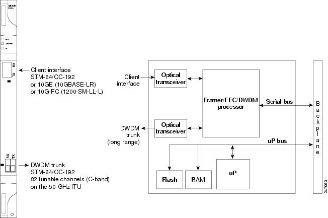
For information on safety labels for the card, see the “Class 1M Laser Product Cards” section.
10.15.3 Client Interface
The client interface is implemented with a separately orderable XFP module. The module is a tri-rate transceiver, providing a single port that can be configured in the field to support an OC-192 SR-1 (Telcordia GR-253-CORE) or STM-64 I-64.1 (ITU-T G.691) optical interface, as well as 10GE LAN PHY (10GBASE-LR), 10GE WAN PHY (10GBASE-LW), 10G-FC, or IB_5G signals.
The client-side XFP pluggable module supports LC connectors and is equipped with a 1310-nm laser.
10.15.4 DWDM Trunk Interface
On the trunk side, the TXP_MR_10EX_C card provides a 10-Gbps STM-64/OC-192 interface. In the 1550-nm C-band on the 50-GHz ITU grid for the DWDM interface, 82 tunable channels are available. The TXP_MR_10EX_C card provides 3R transponder functionality for this 10-Gbps trunk interface. Therefore, the card is suited for use in long-range amplified systems. The DWDM interface is compliant with ITU-T G.707, ITU-T G.709, and Telcordia GR-253-CORE standards.
The DWDM trunk port operates at a rate that depends on the input signal and the presence of the ITU-T G.709 Digital Wrapper/FEC. The possible trunk rates are:
- OC192 (9.95328 Gbps)
- OTU2 (10.70923 Gbps)
- 10GE (10.3125 Gbps) or 10GE into OTU2 (ITU G.sup43 11.0957 Gbps)
- 10G-FC (10.51875 Gbps) or 10G-FC into OTU2 (nonstandard 11.31764 Gbps)
- Proprietary rate at the trunk when the client is provisioned as IB_5G.
The maximum system reach in filterless applications without the use of optical amplification or regenerators is nominally rated at 23 dB over C-SMF fiber. This rating is not a product specification, but is given for informational purposes. It is subject to change.
Note![]() You cannot disable ITU-T G.709 on the trunk side. If ITU-T G.709 is enabled, then FEC cannot be disabled.
You cannot disable ITU-T G.709 on the trunk side. If ITU-T G.709 is enabled, then FEC cannot be disabled.
10.15.5 Enhanced FEC (E-FEC) Feature
A key feature of the TXP_MR_10EX_C card is the availability to configure the forward error correction feature in two modes: FEC and E-FEC. The output bit rate is always 10.7092 Gbps as defined in ITU-T G.709, but the error coding performance can be provisioned as follows:
10.15.6 FEC and E-FEC Modes
As client-side traffic passes through the TXP_MR_10EX_C card, it can be digitally wrapped using FEC mode or E-FEC mode. The FEC mode setting provides a lower level of error detection and correction than the E-FEC mode setting of the card. As a result, using E-FEC mode allows higher sensitivity (lower OSNR) with a lower bit error rate than FEC mode. E-FEC enables longer distance trunk-side transmission than with FEC.
The E-FEC feature is one of three basic modes of FEC operation. FEC can be turned on, or E-FEC can be turned on to provide greater range and lower BER. The default mode is FEC on and E-FEC off. E-FEC is provisioned using CTC.
10.15.7 Client-to-Trunk Mapping
The TXP_MR_10EX_C card can perform ODU2-to-OCh mapping, which allows operators to provision data payloads in a standard way across 10-Gbps optical links.
Digital wrappers that define client-side interfaces are called ODU2 entities in ITU-T G.709. Digital wrappers that define trunk-side interfaces are called OCh in ITU-T G.709. ODU2 digital wrappers can include G-MPLS signaling extensions to ITU-T G.709 (such as LSP and G-PID values) to define client interfaces and payload protocols.
10.15.8 Automatic Laser Shutdown
The ALS procedure is supported on both client and trunk interfaces. On the client interface, ALS is compliant with ITU-T G.664 (6/99). On the data application and trunk interface, the switch on and off pulse duration is greater than 60 seconds and is user-configurable. For details regarding ALS provisioning for the TXP_MR_10EX_C card, refer to the Cisco ONS 15454 DWDM Procedure Guide.
10.15.9 TXP_MR_10EX_C Card-Level Indicators
Table 10-43 lists the card-level LEDs on the TXP_MR_10EX_C card.
10.15.10 TXP_MR_10EX_C Port-Level Indicators
Table 10-44 lists the port-level LEDs on the TXP_MR_10EX_C card.
10.16 MXP_2.5G_10EX_C card
The MXP_2.5G_10EX_C card is a DWDM muxponder for the ONS 15454 platform that supports transparent termination mode on the client side. The faceplate designation of the card is “4x2.5G 10EX MXP.” The card multiplexes four 2.5-Gbps client signals (4xOC48/STM-16 SFP) into a single 10-Gbps DWDM optical signal on the trunk side. The card provides wavelength transmission service for the four incoming 2.5-Gbps client interfaces. The MXP_2.5G_10EX_C muxponder passes all SONET/SDH overhead bytes transparently.
The digital wrapper function (ITU-T G.709 compliant) formats the DWDM wavelength so that it can be used to set up GCCs for data communications, enable FEC, or facilitate PM.
The MXP_2.5G_10EX_C card works with OTN devices defined in ITU-T G.709. The card supports ODU1 to OTU2 multiplexing, an industry standard method for asynchronously mapping a SONET/SDH payload into a digitally wrapped envelope. See the “Multiplexing Function” section.
The MXP_2.5G_10EX_C card is not compatible with the MXP_2.5G_10G card, which does not support transparent termination mode.
You can install the MXP_2.5G_10EX_C card in slots 1 to 6 and 12 to 17. You can provision a card in a linear configuration, a BLSR/MS-SPRing, a path protection/SNCP, or a regenerator. The card can be used in the middle of BLSR/MS-SPRing or 1+1 spans when the card is configured for transparent termination mode.
The MXP_2.5G_10EX_C card features a tunable 1550-nm C-band laser on the trunk port. The laser is tunable across 82 wavelengths on the ITU grid with 50-GHz spacing between wavelengths. The card features four 1310-nm lasers on the client ports and contains five transmit and receive connector pairs (labeled) on the card faceplate. The card uses dual LC connectors on the trunk side and SFP modules on the client side for optical cable termination. The SFP pluggable modules are SR or IR and support an LC fiber connector.
Note![]() When you create a 4xOC-48 OCHCC circuit, you need to select the G.709 and Synchronous options. A 4xOC-48 OCHCC circuit is supported by G.709 and synchronous mode, which are necessary to provision the 4xOC-48 OCHCC circuit.
When you create a 4xOC-48 OCHCC circuit, you need to select the G.709 and Synchronous options. A 4xOC-48 OCHCC circuit is supported by G.709 and synchronous mode, which are necessary to provision the 4xOC-48 OCHCC circuit.
10.16.1 Key Features
The MXP_2.5G_10EX_C card has the following high-level features:
- Four 2.5-Gbps client interfaces (OC-48/STM-16) and one 10-Gbps trunk. The four OC-48 signals are mapped into an ITU-T G.709 OTU2 signal using standard ITU-T G.709 multiplexing.
- Onboard E-FEC processor: The processor supports both standard RS (specified in ITU-T G.709) and E-FEC, which allows an improved gain on trunk interfaces with a resultant extension of the transmission range on these interfaces. The E-FEC functionality increases the correction capability of the transponder to improve performance, allowing operation at a lower OSNR compared to the standard RS (237,255) correction algorithm.
- Pluggable client-interface optic modules: The MXP_2.5G_10EX_C card has modular interfaces. Two types of optic modules can be plugged into the card. These modules include an OC-48/STM-16 SR-1 interface with a 7-km (4.3-mile) nominal range (for short range and intra-office applications) and an IR-1 interface with a range of up to 40 km (24.9 miles). SR-1 is defined in Telcordia GR-253-CORE and in I-16 (ITU-T G.957). IR-1 is defined in Telcordia GR-253-CORE and in S-16-1 (ITU-T G.957).
- High-level provisioning support: The card is initially provisioned using Cisco TransportPlanner software. Subsequently, the card can be monitored and provisioned using CTC software.
- Link monitoring and management: The card uses standard OC-48 OH (overhead) bytes to monitor and manage incoming interfaces. The card passes the incoming SDH/SONET data stream and its overhead bytes transparently.
- Control of layered SONET/SDH transport overhead: The card is provisionable to terminate regenerator section overhead, which eliminates forwarding of unneeded layer overhead. It can help reduce the number of alarms and help isolate faults in the network.
- Automatic timing source synchronization: The MXP_2.5G_10EX_C card normally synchronizes from the TCC2/TCC2P card. If for some reason, such as maintenance or upgrade activity, the TCC2/TCC2P is not available, the card automatically synchronize to one of the input client-interface clocks.
- Configurable squelching policy: The card can be configured to squelch the client interface output if LOS occurs at the DWDM receiver or if a remote fault occurs. In the event of a remote fault, the card manages MS-AIS insertion.
- The card is tunable across the full C-band, thus eliminating the need to use different versions of each card to provide tunability across specific wavelengths in a band.
10.16.2 Faceplate
Figure 10-32 shows the MXP_2.5G_10EX_C faceplate and block diagram.
Figure 10-32 MXP_2.5G_10EX_C Faceplate and Block Diagram
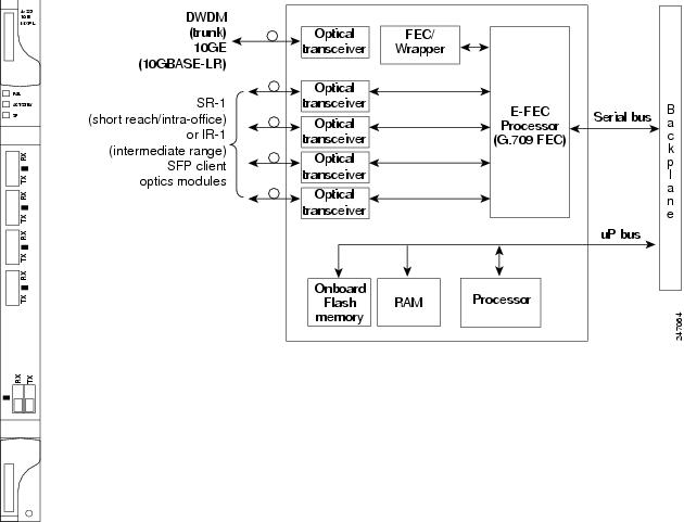
For information on safety labels for the card, see the “Class 1 Laser Product Cards” section.
10.16.3 Client Interfaces
The MXP_2.5G_10EX_C card provides four intermediate- or short-range OC-48/STM-16 ports per card on the client side. Both SR-1 and IR-1 optics can be supported and the ports use SFP connectors. The client interfaces use four wavelengths in the 1310-nm, ITU 100-GHz-spaced, channel grid.
10.16.4 DWDM Interface
The MXP_2.5G_10EX_C card serves as OTN multiplexers, transparently mapping four OC-48 channels asynchronously to ODU1 into one 10-Gbps trunk. For the MXP_2.5G_10EX_C card, the DWDM trunk is tunable for transmission over the entire C-band. Channels are spaced at 50-GHz on the ITU grid.
Note![]() You cannot disable ITU-T G.709 on the trunk side. If ITU-T G.709 is enabled, then FEC cannot be disabled.
You cannot disable ITU-T G.709 on the trunk side. If ITU-T G.709 is enabled, then FEC cannot be disabled.
10.16.5 Multiplexing Function
The muxponder is an integral part of the ROADM network. The key function of the MXP_2.5G_10EX_C card is to multiplex four OC-48/STM-16 signals onto one ITU-T G.709 OTU2 optical signal (DWDM transmission). The multiplexing mechanism allows the signal to be terminated at a far-end node by another similar card.
Transparent termination on the muxponder is configured using OTUx and ODUx OH bytes. The ITU-T G.709 specification defines OH byte formats that are used to configure, set, and monitor frame alignment, FEC mode, section monitoring, tandem connection monitoring, and transparent termination mode.
The MXP_2.5G_10EX_C card performs ODU to OTU multiplexing as defined in ITU-T G.709. The ODU is the framing structure and byte definition (ITU-T G.709 digital wrapper) used to define the data payload coming into one of the SONET/SDH client interfaces on the card. The term ODU1 refers to an ODU that operates at 2.5-Gbps line rate. On the card, four client interfaces can be defined using ODU1 framing structure and format by asserting an ITU-T G.709 digital wrapper.
The output of the muxponder is a single 10-Gbps DWDM trunk interface defined using OTU2. It is within the OTU2 framing structure that FEC or E-FEC information is appended to enable error checking and correction.
10.16.6 Timing Synchronization
The MXP_2.5G_10EX_C card is synchronized to the TCC2/TCC2P clock during normal conditions and transmits the ITU-T G.709 frame using this clock. No holdover function is implemented. If neither TCC2/TCC2P clock is available, the card switches automatically (hitless) to the first of the four valid client clocks with no time restriction as to how long it can run on this clock. The card continues to monitor the TCC2/TCC2P card. If a TCC2/TCC2P card is restored to working order, the card reverts to the normal working mode of running from the TCC2/TCC2P clock. If no valid TCC2/TCC2P clock is available and all of the client channels become invalid, the card waits (no valid frames processed) until one of the TCC2/TCC2P cards supplies a valid clock. In addition, the card is allowed to select the recovered clock from one active and valid client channel and supply that clock to the TCC2/TCC2P card.
10.16.7 Enhanced FEC (E-FEC) Capability
The MXP_2.5G_10EX_C card can configure the FEC in two modes: FEC and E-FEC. The output bit rate is always 10.7092 Gbps as defined in ITU-T G.709, but the error coding performance can be provisioned as follows:
- FEC—Standard ITU-T G.975 Reed-Solomon algorithm
- E-FEC—Standard ITU-T G.975.1 I.7, two orthogonally concatenated BCH super FEC codes. This FEC scheme contains three parameterizations of the same scheme of two orthogonally interleaved block codes (BCH). The constructed code is decoded iteratively to achieve the expected performance.
10.16.8 FEC and E-FEC Modes
As client-side traffic passes through the card, it can be digitally wrapped using FEC mode error correction or E-FEC mode error correction. The FEC mode setting provides a lower level of error detection and correction than the E-FEC mode setting of the card. As a result, using E-FEC mode allows higher sensitivity (lower OSNR) with a lower BER than FEC mode. E-FEC enables longer distance trunk-side transmission than with FEC.
The E-FEC feature is one of three basic modes of FEC operation. FEC can be turned on, or E-FEC can be turned on to provide greater range and lower BER. The default mode is FEC on and E-FEC off. E-FEC is provisioned using CTC.
10.16.9 SONET/SDH Overhead Byte Processing
The card passes the incoming SONET/SDH data stream and its overhead bytes for the client signal transparently. The card can be provisioned to terminate regenerator section overhead, which eliminates forwarding of unneeded layer overhead. It can help reduce the number of alarms and help isolate faults in the network.
10.16.10 Client Interface Monitoring
The following parameters are monitored on the MXP_2.5G_10EX_C card:
- Laser bias current is measured as a PM parameter.
- LOS is detected and signaled.
- Rx and Tx power are monitored.
The following parameters are monitored in real-time mode (one second):
In the case of LOC at the DWDM receiver or far-end LOS, the client interface behavior is configurable. AIS can be invoked or the client signal can be squelched.
10.16.11 Wavelength Identification
The card uses trunk lasers that are wavelocked, which allows the trunk transmitter to operate on the ITU grid effectively. The MXP_2.5G_10EX_C card implements the MLSE-based UT module. The MXP_2.5G_10EX_C card uses a C-band version of the UT2.
Table 10-45 describes the required trunk transmit laser wavelengths for the MXP_2.5G_10EX_C card. The laser is tunable over 82 wavelengths in the C-band at 50-GHz spacing on the ITU grid.
|
|
|
|
|
|
|
|---|---|---|---|---|---|
10.16.12 Automatic Laser Shutdown
The ALS procedure is supported on both client and trunk interfaces. On the client interface, ALS is compliant with ITU-T G.664 (6/99). On the data application and trunk interface, the switch on and off pulse duration is greater than 60 seconds and is user-configurable. For details regarding ALS provisioning for the MXP_2.5G_10EX_C card, see the Cisco ONS 15454 DWDM Procedure Guide.
10.16.13 Jitter
For SONET and SDH signals, the MXP_2.5G_10EX_C card complies with Telcordia GR-253-CORE, ITU-T G.825, and ITU-T G.873 for jitter generation, jitter tolerance, and jitter transfer. See the “Jitter Considerations” section for more information.
10.16.14 Lamp Test
The MXP_2.5G_10EX_C card supports a lamp test function that is activated from the ONS 15454 front panel or through CTC to ensure that all LEDs are functional.
10.16.15 Onboard Traffic Generation
The MXP_2.5G_10EX_C card provides internal traffic generation for testing purposes according to PRBS, SONET/SDH, or ITU-T G.709.
10.16.16 MXP_2.5G_10EX_C Card-Level Indicators
Table 10-46 describes the card-level LEDs on the MXP_2.5G_10EX_C card.
10.16.17 MXP_2.5G_10EX_C Port-Level Indicators
Table 10-47 describes the port-level LEDs on the MXP_2.5G_10EX_C card.
10.17 MXP_MR_10DMEX_C Card
The MXP_MR_10DMEX_C card aggregates a mix of client SAN service-client inputs (GE, FICON, and Fibre Channel) into one 10-Gbps STM-64/OC-192 DWDM signal on the trunk side. It provides one long-reach STM-64/OC-192 port per card and is compliant with Telcordia GR-253-CORE and ITU-T G.957.
The card supports aggregation of the following signal types:
- 1-Gigabit Fibre Channel
- 2-Gigabit Fibre Channel
- 4-Gigabit Fibre Channel
- 1-Gigabit Ethernet
- 1-Gigabit ISC-Compatible (ISC-1)
- 2-Gigabit ISC-Peer (ISC-3)
The MXP_MR_10DMEX_C muxponder passes all SONET/SDH overhead bytes transparently.
The digital wrapper function (ITU-T G.709 compliant) formats the DWDM wavelength so that it can be used to set up GCCs for data communications, enable FEC, or facilitate PM. The MXP_MR_10DMEX_C card works with the OTN devices defined in ITU-T G.709. The card supports ODU1 to OTU2 multiplexing, an industry standard method for asynchronously mapping a SONET/SDH payload into a digitally wrapped envelope. See the “Multiplexing Function” section.
Note![]() You cannot disable ITU-T G.709 on the trunk side. If ITU-T G.709 is enabled, then FEC cannot be disabled.
You cannot disable ITU-T G.709 on the trunk side. If ITU-T G.709 is enabled, then FEC cannot be disabled.
Note![]() Because the client payload cannot oversubscribe the trunk, a mix of client signals can be accepted, up to a maximum limit of 10 Gbps.
Because the client payload cannot oversubscribe the trunk, a mix of client signals can be accepted, up to a maximum limit of 10 Gbps.
You can install the MXP_MR_10DMEX_C card in slots 1 to 6 and 12 to 17.
Note![]() The MXP_MR_10DMEX_C card is not compatible with the MXP_2.5G_10G card, which does not support transparent termination mode.
The MXP_MR_10DMEX_C card is not compatible with the MXP_2.5G_10G card, which does not support transparent termination mode.
The MXP_MR_10DMEX_C card features a tunable 1550-nm C-band laser on the trunk port. The laser is tunable across 82 wavelengths on the ITU grid with 50-GHz spacing between wavelengths. Each card features four 1310-nm lasers on the client ports and contains five transmit and receive connector pairs (labeled) on the card faceplate. The card uses dual LC connectors on the trunk side and SFP modules on the client side for optical cable termination. The SFP pluggable modules are SR or IR and support an LC fiber connector.
Table 10-48 shows the input data rate for each client interface, and the encapsulation method. The current version of the GFP-T G.7041 supports transparent mapping of 8B/10B block-coded protocols, including Gigabit Ethernet, Fibre Channel, ISC, and FICON.
In addition to the GFP mapping, 1-Gbps traffic on Port 1 or 2 of the high-speed SERDES is mapped to an STS-24c channel. If two 1-Gbps client signals are present at Port 1 and Port 2 of the high-speed SERDES, the Port 1 signal is mapped into the first STS-24c channel and the Port 2 signal into the second STS-24c channel. The two channels are then mapped into an OC-48 trunk channel.
|
|
|
|
|---|---|---|
The MXP_MR_10DMEX_C card includes two FPGAs, and a group of four ports is mapped to each FPGA. Group 1 consists of Ports 1 through 4, and Group 2 consists of Ports 5 through 8. Table 10-49 shows some of the mix and match possibilities on the various client data rates for Ports 1 through 4, and Ports 5 through 8. An X indicates that the data rate is supported in that port.
|
|
|
|
|
|
|
|---|---|---|---|---|---|
GFP-T PM is available through RMON and trunk PM is managed according to Telcordia GR-253-CORE and ITU G.783/826. Client PM is achieved through RMON for FC and GE.
A buffer-to-buffer credit management scheme provides FC flow control. With this feature enabled, a port indicates the number of frames that can be sent to it (its buffer credit), before the sender is required to stop transmitting and wait for the receipt of a “ready” indication. The MXP_MR_10DMEX_C card supports FC credit-based flow control with a buffer-to-buffer credit extension of up to 1600 km (994.1 miles) for 1G FC, up to 800 km (497.1 miles) for 2G FC, or up to 400 km (248.5 miles) for 4G FC. The feature can be enabled or disabled.
The MXP_MR_10DMEX_C card features a 1550-nm laser for the trunk/line port and a 1310-nm or 850-nm laser (depending on the SFP) for the client ports. The card contains eight 12.5-degree downward-tilt SFP modules for the client interfaces. For optical termination, each SFP uses two LC connectors, which are labeled TX and RX on the faceplate. The trunk port is a dual-LC connector with a 45-degree downward angle.
10.17.1 Key Features
The MXP_MR_10DMEX_C card has the following high-level features:
- Onboard E-FEC processor: The processor supports both standard RS (specified in ITU-T G.709) and E-FEC, which allows an improved gain on trunk interfaces with a resultant extension of the transmission range on these interfaces. The E-FEC functionality increases the correction capability of the transponder to improve performance, allowing operation at a lower OSNR compared to the standard RS (237,255) correction algorithm.
- Pluggable client-interface optic modules: The MXP_MR_10DMEX_C card has modular interfaces. Two types of optics modules can be plugged into the card. These modules include an OC-48/STM-16 SR-1 interface with a 7-km (4.3-mile) nominal range (for short range and intra-office applications) and an IR-1 interface with a range of up to 40 km (24.9 miles). SR-1 is defined in Telcordia GR-253-CORE and in I-16 (ITU-T G.957). IR-1 is defined in Telcordia GR-253-CORE and in S-16-1 (ITU-T G.957).
- Y-cable protection: The card supports Y-cable protection between the same card type only, on ports with the same port number and signal rate. See the “Y-Cable Protection” section for more detailed information.
- High-level provisioning support: The card is initially provisioned using Cisco TransportPlanner software. Subsequently, the card can be monitored and provisioned using CTC software.
- ALS: This safety mechanism is used in the event of a fiber cut. For details regarding ALS provisioning for the MXP_MR_10DMEX_C card, refer to the Cisco ONS 15454 DWDM Procedure Guide.
- Link monitoring and management: The card uses standard OC-48 OH(overhead) bytes to monitor and manage incoming interfaces. The card passes the incoming SDH/SONET data stream and its OH(overhead) bytes transparently.
- Control of layered SONET/SDH transport overhead: The card is provisionable to terminate regenerator section overhead, which eliminates forwarding of unneeded layer overhead. It can help reduce the number of alarms and help isolate faults in the network.
- Automatic timing source synchronization: The MXP_MR_10DMEX_C card normally synchronizes from the TCC2/TCC2P card. If for some reason, such as maintenance or upgrade activity, the TCC2/TCC2P is not available, the card automatically synchronizes to one of the input client-interface clocks.
Note![]() MXP_MR_10DMEX_C card cannot be used for line timing.
MXP_MR_10DMEX_C card cannot be used for line timing.
- Configurable squelching policy: The card can be configured to squelch the client-interface output if LOS occurs at the DWDM receiver or if a remote fault occurs. In the event of a remote fault, the card manages MS-AIS insertion.
- The card is tunable across the full C-band, thus eliminating the need to use different versions of each card to provide tunability across specific wavelengths in a band.
- You can provision a string (port name) for each fiber channel/FICON interface on the MXP_MR_10DMEX_C card, which allows the MDS Fabric Manager to create a link association between that SAN port and a SAN port on a Cisco MDS 9000 switch.
10.17.2 Faceplate
Figure 10-33 shows the MXP_MR_10DMEX_C faceplate and block diagram.
Figure 10-33 MXP_MR_10DMEX_C Faceplate and Block Diagram
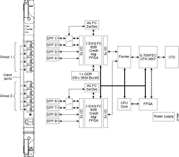
For information on safety labels for the card, see the “Class 1M Laser Product Cards” section.
10.17.3 Wavelength Identification
The card uses trunk lasers that are wavelocked, which allows the trunk transmitter to operate on the ITU grid effectively. The MXP_MR_10DMEX_C card uses a C-band version of the MLSE-based UT module.
Table 10-50 describes the required trunk transmit laser wavelengths for the MXP_MR_10DMEX_C card. The laser is tunable over 82 wavelengths in the C-band at 50-GHz spacing on the ITU grid.
|
|
|
|
|
|
|
|---|---|---|---|---|---|
10.17.4 MXP_MR_10DMEX_C Card-Level Indicators
Table 10-51 describes the card-level LEDs on the MXP_MR_10DMEX_C card.
10.17.5 MXP_MR_10DMEX_C Port-Level Indicators
Table 10-52 describes the port-level LEDs on the MXP_MR_10DMEX_C card.
10.18 Y-Cable and Splitter Protection
Y-cable and splitter protection are two main forms of card protection that are available for TXP, MXP, and Xponder (GE_XP, 10GE_XP, GE_XPE, 10GE_XPE, and OTU2_XP) cards when they are provisioned in TXP or MXP mode. Y-cable protection is provided at the client port level. Splitter protection is provided at the trunk port level.
Note![]() GE_XP, 10GE_XP, GE_XPE, and 10GE_XPE cards use VLAN protection when they are provisioned in L2-over-DWDM mode. For information, see the “Layer 2 Over DWDM Protection” section. The ADM-10G card uses path protection and 1+1 protection. For more information, see the “Protection” section.
GE_XP, 10GE_XP, GE_XPE, and 10GE_XPE cards use VLAN protection when they are provisioned in L2-over-DWDM mode. For information, see the “Layer 2 Over DWDM Protection” section. The ADM-10G card uses path protection and 1+1 protection. For more information, see the “Protection” section.
10.18.1 Y-Cable Protection
Y-cable protection is available for the following ONS 15454 TXP, MXP, and Xponder cards:
- TXP_MR_10G
- TXP_MR_10E
- TXP_MR_2.5G
- MXP_2.5G_10G
- MXP_2.5G_10E
- MXP_2.5G_10E_C
- MXP_2.5G_10E_L
- MXP_MR_2.5G
- MXP_MR_10DME_C
- MXP_MR_10DME_L
- GE_XP and GE_XPE (when in 10GE or 20GE MXP card mode)
- 10GE_XP and 10GE_XPE (when in 10GE TXP card mode)
- OTU2_XP (when in Transponder card configuration)
When an MXP_MR_2.5G, MXP_MR_10DME_C, or MXP_MR_10DME_L card that is provisioned with Y-cable protection is used on a storage ISL link (FC1G, FC2G, FC4G, FICON1G, FICON2G, or FICON4G), a protection switchover resets the standby port to active. This reset reinitialises the end-to-end link to avoid any link degradation caused due to loss of buffer credits during switchover and results in an end-to-end traffic hit of 15 to 20 seconds.
When using the MXP_MR_10DME_C or MXP_MR_10DME_L card, enable the fast switch feature and use it with a Cisco MDS storage switch to avoid this 15 to 20 second traffic hit. When enabling fast switch on the MXP_MR_10DME_C or MXP_MR_10DME_L card, ensure that the attached MDS switches have the buffer-to-buffer credit recovery feature enabled.
You can also use the TXP_MR_2.5G card to avoid this 15 to 20 second traffic hit. When a Y-cable protection switchover occurs, the storage ISL link does not reinitialize and results in an end-to-end traffic hit of less than 50ms.
Note![]() Y-cable connectors will not work with copper SFPs because Y-cables are made up of optical connectors and there is no way to physically connect them to a copper SFP. Y-cable protection is not supported on IB_5G.
Y-cable connectors will not work with copper SFPs because Y-cables are made up of optical connectors and there is no way to physically connect them to a copper SFP. Y-cable protection is not supported on IB_5G.
Note![]() There is a traffic hit of upto a couple hundred milliseconds on the MXP_MR_2.5G and MXP_MR_10DME cards in Y-cable configuration when a fiber cut or SFP failure occurs on one of the client ports.
There is a traffic hit of upto a couple hundred milliseconds on the MXP_MR_2.5G and MXP_MR_10DME cards in Y-cable configuration when a fiber cut or SFP failure occurs on one of the client ports.
Note![]() The OTU2-XP and 40E-MXP-C card cannot implement Y-cable protection for the client ports in 10 GE LAN PHY mode. Hence, a pair of OTU2_XP cards is used at each end in pass-through mode (Transponder mode with G.709 disabled) to implement Y-cable protection. The 40E-MXP-CE card can implement Y-cable protection without the OTU2-XP card for the client ports in LAN PHY GFP mode. However, the 40E-MXP-CE card cannot implement Y-cable protection without the OTU2-XP card for the client ports in LAN PHY WIS mode.
The OTU2-XP and 40E-MXP-C card cannot implement Y-cable protection for the client ports in 10 GE LAN PHY mode. Hence, a pair of OTU2_XP cards is used at each end in pass-through mode (Transponder mode with G.709 disabled) to implement Y-cable protection. The 40E-MXP-CE card can implement Y-cable protection without the OTU2-XP card for the client ports in LAN PHY GFP mode. However, the 40E-MXP-CE card cannot implement Y-cable protection without the OTU2-XP card for the client ports in LAN PHY WIS mode.
Note![]() If you create a GCC on either card of the protect group, the trunk port stays permanently active, regardless of the switch state. When you provision a GCC, you are provisioning unprotected overhead bytes. The GCC is not protected by the protect group.
If you create a GCC on either card of the protect group, the trunk port stays permanently active, regardless of the switch state. When you provision a GCC, you are provisioning unprotected overhead bytes. The GCC is not protected by the protect group.
Figure 10-34 shows the Y-cable signal flow.
Note![]() Loss of Signal–Payload (LOS-P) alarms, also called Incoming Payload Signal Absent alarms, can occur on a split signal if the ports are not in a Y-cable protection group.
Loss of Signal–Payload (LOS-P) alarms, also called Incoming Payload Signal Absent alarms, can occur on a split signal if the ports are not in a Y-cable protection group.
Note![]() Removing an SFP from the client ports of a card in a Y-cable protection group card causes an IMPROPRMVL (PPM) alarm. The working port raises the IMPROPRMVL alarm and the protected port raises the IMPROPRMVL alarm. The severity on the client ports is changed according to the protection switch state.
Removing an SFP from the client ports of a card in a Y-cable protection group card causes an IMPROPRMVL (PPM) alarm. The working port raises the IMPROPRMVL alarm and the protected port raises the IMPROPRMVL alarm. The severity on the client ports is changed according to the protection switch state.
Figure 10-34 Y-Cable Protection
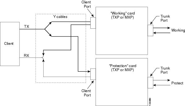
10.18.2 Splitter Protection
Splitter protection, shown in Figure 10-35, is provided with TXPP cards, MXPP cards., and OTU2_XP cards (on trunk ports that are not part of a regenerator group). You can create and delete splitter protection groups in OTU2_XP card.
To implement splitter protection, a client injects a single signal into the client RX port. An optical splitter internal to the card then splits the signal into two separate signals and routes them to the two trunk TX ports. The two signals are transmitted over diverse optical paths. The far-end MXPP or TXPP card uses an optical switch to choose one of the two trunk RX port signals and injects it into the TX client port. When using splitter protection with two MXPP or TXPP cards, there are two different optical signals that flow over diverse paths in each direction. In case of failure, the far-end switch must choose the appropriate signal using its built-in optical switch. The triggers for a protection switch are LOS, LOF, SF, or SD.
Figure 10-35 Splitter Protection
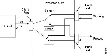
10.19 Far-End Laser Control
The 15454 DWDM cards provide a transparent mode that accurately conveys the client input signal to the far-end client output signal. The client signal is normally carried as payload over the DWDM signals. Certain client signals, however, cannot be conveyed as payload. In particular, client LOS or LOF cannot be carried. Far-end laser control (FELC) is the ability to convey an LOS or LOF from the near-end client input to the far-end client output.
If an LOS is detected on the near-end client input, the near-end trunk sets the appropriate bytes in the OTN overhead of the DWDM line. These bytes are received by the far-end trunk, and cause the far-end client laser to be turned off. When the laser is turned off, it is said to be squelched. If the near-end LOS clears, the near-end trunk clears the appropriate bytes in the OTN overhead, the far-end detects the changed bytes, and the far-end client squelch is removed.
FELC also covers the situation in which the trunk port detects that it has an invalid signal; the client is squelched so as not to propagate the invalid signal.
Payload types with the 2R mode preclude the use of OTN overhead bytes. In 2R mode, an LOS on the client port causes the trunk laser to turn off. The far end detects the LOS on its trunk receiver and squelches the client.
FELC is not provisionable. It is always enabled when the DWDM card is in transparent termination mode. However, FELC signaling to the far-end is only possible when ITU-T G.709 is enabled on both ends of the trunk span.
10.20 Jitter Considerations
Jitter introduced by the SFPs used in the transponders and muxponders must be considered when cascading several cards. With TXP_MR_2.5G, TXPP_MR_2.5G, MXP_MR_2.5G, MXPP_MR_2.5G, and TXP_MR_10E cards, several transponders can be cascaded before the cumulative jitter violates the jitter specification. The recommended limit is 20 cards. With TXP_MR_10G cards, you can also cascade several cards, although the recommended limit is 12 cards. With MXP_2.5G_10G and MXP_2.5G_10E cards, any number of cards can be cascaded as long as the maximum reach between any two is not exceeded. This is because any time the signal is demultiplexed, the jitter is eliminated as a limiting factor.
The maximum reach between one transponder and the other must be halved if a Y cable is used. For more information on Y-cable operation, see the “Y-Cable Protection” section.
10.21 Termination Modes
Transponder and muxponder cards have various SONET and SDH termination modes that can be configured using CTC (see the “Provision Transponder and Muxponder Cards” chapter in the Cisco ONS 15454 DWDM Procedure Guide). The termination modes are summarized in Table 10-53 .
|
|
|
|
|---|---|---|
| All TXP, MXP, and OTU2_XP cards, with the exception of the MXP_2.5G_10G card (see next section of this table) |
All the bytes of the payload pass transparently through the cards. |
|
The SONET transport overhead (TOH) section bytes and the SDH regenerator section overhead (SOH) bytes are terminated. None of these SOH bytes are passed through. They are all regenerated, including the SONET TOH section DCC (SDCC) bytes and the SDH regenerator section DCC (RS-DCC) bytes. In the section termination mode, the SONET TOH line and SDH multiplex section overhead bytes are passed transparently. |
||
In line termination mode, the section and line overhead bytes for SONET and the overhead bytes for the SDH multiplex and regenerator sections are terminated. None of the overhead bytes are passed through. They are all regenerated, including the SONET SDCC and line DCC (LDCC) bytes and the SDH RS-DCC and multiplexer section DCC (MS-DCC) bytes. |
||
| MXP_2.5G_10G3 |
All client bytes pass transparently except the following: B1 is rebuilt, S1 is rewritten, A1 to A2 are regenerated, and H1 to H3 are regenerated. |
|
The SONET TOH section bytes and the SDH regenerator section overhead bytes are terminated. None of these section overhead bytes are passed through. They are all regenerated, including the SONET TOH section DCC bytes and the SDH RS-DCC bytes. In the section termination mode, the SONET TOH line and SDH multiplex section overhead bytes are passed transparently. |
||
In the line termination mode, the section and line overhead bytes for SONET and the overhead bytes for the SDH multiplex and regenerators sections are terminated. None of the overhead bytes are passed through. They are all regenerated, including the SONET SDCC and LDCC bytes and the SDH RS-DCC and MS-DCC bytes. |
|
3.Clients operating at the OC48/STM16 rate are multiplexed into an OC192/STM64 frame before going to OTN or DWDM. |
For TXP and MXP cards, adhere to the following conditions while DCC termination provisioning:
- For SDCC/RS-DCC provisioning, the card should be in the Section/RS-DCC or Line/MS-DCC termination mode.
- For LDCC/MS-DCC provisioning, the card should be in the Line/MS-DCC termination mode.
For more information on enabling termination modes, see the procedures for changing card setting in the “Provision Transponder and Muxponder Cards” chapter of the Cisco ONS 15454 DWDM Procedure Guide.
10.22 SFP and XFP Modules
SFPs and 10-Gbps SFPs (XFPs) are integrated fiber optic transceivers that provide high-speed serial links from a port or slot to the network. For more information on SFPs/XFPs and for a list of SFPs/XFPs supported by the transponder and muxponder cards, see the Installing the GBIC, SFP, SFP+, XFP, CXP, and CFP Optical Modules in Cisco ONS Platforms.
In CTC, SFPs/XFPs are called pluggable port modules (PPMs). To provision SFPs/XFPs and change the line rate for multirate PPMs, see the Cisco ONS 15454 DWDM Procedure Guide.
 Feedback