- About This Guide
- Chapter 1, Install the Shelf and Common Control Cards
- Chapter 2, Connect the PC and Log into the GUI
- Chapter 3, Turn Up a Node
- Chapter 4, Perform Node Acceptance Tests
- Chapter 5, Provision Transponder and Muxponder Cards
- Chapter 6, Turn Up a Network
- Chapter 7, Create Optical Channel Circuits and Provisionable Patchcords
- Chapter 8, Monitor Performance
- Chapter 9, Manage Alarms
- Chapter 10, Manage the Node
- Chapter 11, Change DWDM Card Settings
- Chapter 12, Upgrade, Add, and Remove Cards and Nodes
- Chapter 13, Maintain the Node
- Chapter 14, Power Down a Node
- Appendix A, CTC Information and Shortcuts
- Appendix B, Installation Without Cisco Transport Planner
- Appendix C, Configuring GE_XP, 10GE_XP, GE_XPE, and 10GE_XPE Cards Using PCLI
Provision Transponder and Muxponder Cards
This chapter explains how to provision transponder (TXP), muxponder (MXP), Xponder (GE_XP, 10GE_XP, GE_XPE, and 10GE_XPE), and ADM-10G cards. The provisioning must be performed before you provision the dense wavelength division multiplexing (DWDM) network and create circuits.

Note![]() Unless otherwise specified, “ONS 15454” refers to both ANSI and ETSI shelf assemblies.
Unless otherwise specified, “ONS 15454” refers to both ANSI and ETSI shelf assemblies.
Before You Begin
Before performing any of the following procedures, investigate all alarms and clear any trouble conditions. Refer to the Cisco ONS 15454 DWDM Troubleshooting Guide as necessary.

This section lists the chapter procedures (NTPs). Turn to a procedure for applicable tasks (DLPs).
1.![]() G128 Manage Pluggable Port Modules—Complete this procedure to provision a multirate pluggable port module (PPM), provision or change the optical line rate of a PPM, or delete a PPM. PPMs provide the fiber interface to the TXP, MXP, and ADM-10G cards. With the exception of the TXP_MR_10G card, all TXPs, MXPs, and ADM-10G cards accept PPMs.
G128 Manage Pluggable Port Modules—Complete this procedure to provision a multirate pluggable port module (PPM), provision or change the optical line rate of a PPM, or delete a PPM. PPMs provide the fiber interface to the TXP, MXP, and ADM-10G cards. With the exception of the TXP_MR_10G card, all TXPs, MXPs, and ADM-10G cards accept PPMs.
2.![]() G33 Create a Y-Cable Protection Group—As needed, complete this procedure for TXP, MXP, GE_XP, 10GE_XP, GE_XPE, 10GE_XPE, or OTU2_XP cards that will be protected with Y-cable protection.
G33 Create a Y-Cable Protection Group—As needed, complete this procedure for TXP, MXP, GE_XP, 10GE_XP, GE_XPE, 10GE_XPE, or OTU2_XP cards that will be protected with Y-cable protection.
3.![]() G199 Create a Splitter Protection Group for the OTU2_XP Card—As needed, complete this procedure to create a splitter protection group for an OTU2_XP card.
G199 Create a Splitter Protection Group for the OTU2_XP Card—As needed, complete this procedure to create a splitter protection group for an OTU2_XP card.
4.![]() G198 Create 1+1 Protection for GE_XP, 10GE_XP, GE_XPE, or 10GE_XPE Cards—As needed, complete this procedure to create 1+1 protection for GE_XP, 10GE_XP, GE_XPE, and 10GE_XPE cards.
G198 Create 1+1 Protection for GE_XP, 10GE_XP, GE_XPE, or 10GE_XPE Cards—As needed, complete this procedure to create 1+1 protection for GE_XP, 10GE_XP, GE_XPE, and 10GE_XPE cards.
5.![]() G98 Provision the 2.5G Multirate Transponder Card Line Settings and PM Parameter Thresholds—As needed, complete this procedure to change the transmission settings for TXP_MR_2.5G and TXPP_MR_2.5G cards.
G98 Provision the 2.5G Multirate Transponder Card Line Settings and PM Parameter Thresholds—As needed, complete this procedure to change the transmission settings for TXP_MR_2.5G and TXPP_MR_2.5G cards.
6.![]() G96 Provision the 10G Multirate Transponder Card Line Settings, PM Parameters, and Thresholds—As needed, complete this procedure to change the transmission settings for TXP_MR_10G, TXP_MR_10E, TXP_MR_10E_C, and TXP_MR_10E_L cards.
G96 Provision the 10G Multirate Transponder Card Line Settings, PM Parameters, and Thresholds—As needed, complete this procedure to change the transmission settings for TXP_MR_10G, TXP_MR_10E, TXP_MR_10E_C, and TXP_MR_10E_L cards.
7.![]() G170 Provision the ADM-10G Card Peer Group, Ethernet Settings, Line Settings, PM Parameters, and Thresholds—As needed, complete this procedure to provision the transmission settings for ADM-10G cards.
G170 Provision the ADM-10G Card Peer Group, Ethernet Settings, Line Settings, PM Parameters, and Thresholds—As needed, complete this procedure to provision the transmission settings for ADM-10G cards.
8.![]() G333 Add an ADM-10G card to an Existing Topology—As needed, complete this procedure to add an ADM-10G card to an existing topology.
G333 Add an ADM-10G card to an Existing Topology—As needed, complete this procedure to add an ADM-10G card to an existing topology.
9.![]() G97 Modify the 4x2.5G Muxponder Card Line Settings and PM Parameter Thresholds—As needed, complete this procedure to change the transmission settings for MXP_2.5G_10G, MXP_2.5G_10E, MXP_2.5G_10E_C, and MXP_2.5G_10E_L cards.
G97 Modify the 4x2.5G Muxponder Card Line Settings and PM Parameter Thresholds—As needed, complete this procedure to change the transmission settings for MXP_2.5G_10G, MXP_2.5G_10E, MXP_2.5G_10E_C, and MXP_2.5G_10E_L cards.
10.![]() G99 Modify the 2.5G Data Muxponder Card Line Settings and PM Parameter Thresholds—As needed, complete this procedure to change the transmission settings for MXP_MR_2.5G and MXPP_MR_2.5G cards.
G99 Modify the 2.5G Data Muxponder Card Line Settings and PM Parameter Thresholds—As needed, complete this procedure to change the transmission settings for MXP_MR_2.5G and MXPP_MR_2.5G cards.
11.![]() G148 Modify the 10G Data Muxponder Card Line Settings and PM Parameter Thresholds—As needed, complete this procedure to change the transmission settings for MXP_MR_10DME_C and MXP_MR_10DME_L cards.
G148 Modify the 10G Data Muxponder Card Line Settings and PM Parameter Thresholds—As needed, complete this procedure to change the transmission settings for MXP_MR_10DME_C and MXP_MR_10DME_L cards.
12.![]() G165 Modify the GE_XP, 10GE_XP, GE_XPE, 10GE_XPE Cards Ethernet Parameters, Line Settings, and PM Thresholds—As needed, complete this procedure to change the transmission settings for GE_XP, 10GE_XP, GE_XPE, and 10GE_XPE cards.
G165 Modify the GE_XP, 10GE_XP, GE_XPE, 10GE_XPE Cards Ethernet Parameters, Line Settings, and PM Thresholds—As needed, complete this procedure to change the transmission settings for GE_XP, 10GE_XP, GE_XPE, and 10GE_XPE cards.
13.![]() G314 Add a GE_XP or 10GE_XP Card on a FAPS Ring—As needed, complete this procedure to add a GE_XP or 10GE_XP Card on a FAPS Ring.
G314 Add a GE_XP or 10GE_XP Card on a FAPS Ring—As needed, complete this procedure to add a GE_XP or 10GE_XP Card on a FAPS Ring.
14.![]() G197 Provision the OTU2_XP Card Line Settings, PM Parameters, and Thresholds—As needed, complete this procedure to change the transmission settings for OTU2_XP cards.
G197 Provision the OTU2_XP Card Line Settings, PM Parameters, and Thresholds—As needed, complete this procedure to change the transmission settings for OTU2_XP cards.
15.![]() G162 Change the ALS Maintenance Settings—As needed, complete this procedure to change the automatic laser shutdown settings for a TXP or MXP card.
G162 Change the ALS Maintenance Settings—As needed, complete this procedure to change the automatic laser shutdown settings for a TXP or MXP card.
16.![]() G192 Force FPGA Update—As needed, complete this procedure to force an upgrade of the FPGA image on the MXP_MR_10DME_C and MXP_MR_10DME_L cards.
G192 Force FPGA Update—As needed, complete this procedure to force an upgrade of the FPGA image on the MXP_MR_10DME_C and MXP_MR_10DME_L cards.
17.![]() G196 Force FPGA Update When the Card is Part of a Protection Group—As needed, complete this procedure to force an upgrade of the FPGA image on the MXP_MR_10DME_C and MXP_MR_10DME_L cards when the card is part of a protection group.
G196 Force FPGA Update When the Card is Part of a Protection Group—As needed, complete this procedure to force an upgrade of the FPGA image on the MXP_MR_10DME_C and MXP_MR_10DME_L cards when the card is part of a protection group.
NTP-G128 Manage Pluggable Port Modules
Complete this procedure to provision a multirate PPM, provision the optical line rate of a multirate PPM, or delete a single-rate or multirate PPM. |
|
Note![]() If a single-rate PPM is installed, the PPM screen will autoprovision and no further steps are necessary.
If a single-rate PPM is installed, the PPM screen will autoprovision and no further steps are necessary.
Note![]() When you autoprovision a PPM, initial alarm and TCA defaults are supplied by Cisco Transport Controller (CTC) depending on your port and rate selections and the type of PPM. These default values can be changed after you install the PPM.
When you autoprovision a PPM, initial alarm and TCA defaults are supplied by Cisco Transport Controller (CTC) depending on your port and rate selections and the type of PPM. These default values can be changed after you install the PPM.
Note![]() The hardware device that plugs into a TXP, MXP, GE_XP, 10GE_XP, GE_XPE, 10GE_XPE, ADM-10G, or OTU2_XP card faceplate to provide a fiber interface to the card is called a Small Form-factor Pluggable (SFP or XFP). In CTC, SFPs and XFPs are called pluggable port modules (PPMs). SFPs/XFPs are hot-swappable input/output devices that plug into a port to link the port with the fiber-optic network. Multirate PPMs have provisionable port rates and payloads. For more information about SFPs and XFPs, refer to the “Transponder and Muxponder Cards” chapter in the Cisco ONS 15454 DWDM Reference Manual.
The hardware device that plugs into a TXP, MXP, GE_XP, 10GE_XP, GE_XPE, 10GE_XPE, ADM-10G, or OTU2_XP card faceplate to provide a fiber interface to the card is called a Small Form-factor Pluggable (SFP or XFP). In CTC, SFPs and XFPs are called pluggable port modules (PPMs). SFPs/XFPs are hot-swappable input/output devices that plug into a port to link the port with the fiber-optic network. Multirate PPMs have provisionable port rates and payloads. For more information about SFPs and XFPs, refer to the “Transponder and Muxponder Cards” chapter in the Cisco ONS 15454 DWDM Reference Manual.
Step 1![]() Complete the G46 Log into CTC to log into an ONS 15454 on the network. If you are already logged in, continue with Step 2.
Complete the G46 Log into CTC to log into an ONS 15454 on the network. If you are already logged in, continue with Step 2.
a.![]() Verify that the alarm filter is not turned on. See the G128 Disable Alarm Filtering as necessary.
Verify that the alarm filter is not turned on. See the G128 Disable Alarm Filtering as necessary.
b.![]() Verify that no unexplained conditions appear. If unexplained conditions appear, resolve them before continuing. Refer to the Cisco ONS 15454 DWDM Troubleshooting Guide.
Verify that no unexplained conditions appear. If unexplained conditions appear, resolve them before continuing. Refer to the Cisco ONS 15454 DWDM Troubleshooting Guide.
Step 3![]() If you are provisioning a MXP_MR_2.5G or MXPP_MR_2.5G card, complete the G235 Change the 2.5G Data Muxponder Card Mode. If not, continue with Step 4
If you are provisioning a MXP_MR_2.5G or MXPP_MR_2.5G card, complete the G235 Change the 2.5G Data Muxponder Card Mode. If not, continue with Step 4
Step 4![]() If you are provisioning a MXP_MR_10DME_C or MXP_MR_10DME_L card, complete the G332 Change the 10G Data Muxponder Port Mode. If not, continue with Step 5.
If you are provisioning a MXP_MR_10DME_C or MXP_MR_10DME_L card, complete the G332 Change the 10G Data Muxponder Port Mode. If not, continue with Step 5.
Step 5![]() If you are provisioning a GE_XP, 10GE_XP, GE_XPE, and 10GE_XPE card, complete the G379 Change the GE_XP, 10GE_XP, GE_XPE, and 10GE_XPE Card Mode. If not, continue with Step 6.
If you are provisioning a GE_XP, 10GE_XP, GE_XPE, and 10GE_XPE card, complete the G379 Change the GE_XP, 10GE_XP, GE_XPE, and 10GE_XPE Card Mode. If not, continue with Step 6.
Step 6![]() If you are provisioning a OTU2_XP card, complete the G452 Change the OTU2_XP Card Mode. If not, continue with Step 7.
If you are provisioning a OTU2_XP card, complete the G452 Change the OTU2_XP Card Mode. If not, continue with Step 7.
Step 7![]() If you are provisioning a PPM on an ADM-10G card, complete the G411 Provision an ADM-10G PPM and Port. If not, continue with Step 8.
If you are provisioning a PPM on an ADM-10G card, complete the G411 Provision an ADM-10G PPM and Port. If not, continue with Step 8.
Step 8![]() Complete the G277 Provision a Multirate PPM for TXP, MXP, GE_XP, 10GE_XP, GE_XPE, 10GE_XPE, or OTU2_XP ports with multirate PPMs. If you already preprovisioned the multirate PPM (G273 Preprovision an SFP or XFP Slot), skip this step and continue with Step 9.
Complete the G277 Provision a Multirate PPM for TXP, MXP, GE_XP, 10GE_XP, GE_XPE, 10GE_XPE, or OTU2_XP ports with multirate PPMs. If you already preprovisioned the multirate PPM (G273 Preprovision an SFP or XFP Slot), skip this step and continue with Step 9.
Step 9![]() If you are provisioning an IBM ETR_CLO (External Time Reference – Control Link Oscillator) or InterSystem Coupling Link (ISC) service on the PPM, complete G274 Verify Topologies for ETR_CLO and ISC Services. Otherwise, continue with Step 10.
If you are provisioning an IBM ETR_CLO (External Time Reference – Control Link Oscillator) or InterSystem Coupling Link (ISC) service on the PPM, complete G274 Verify Topologies for ETR_CLO and ISC Services. Otherwise, continue with Step 10.
Step 10![]() Complete the G278 Provision the Optical Line Rate to assign a line rate to a TXP, MXP, or OTU2_XP port after the PPM is provisioned. (This task is not performed for GE_XP, 10GE_XP, GE_XPE, and 10GE_XPE cards.)
Complete the G278 Provision the Optical Line Rate to assign a line rate to a TXP, MXP, or OTU2_XP port after the PPM is provisioned. (This task is not performed for GE_XP, 10GE_XP, GE_XPE, and 10GE_XPE cards.)
Step 11![]() If you need to delete a PPM at any point in this procedure, complete the G280 Delete a PPM.
If you need to delete a PPM at any point in this procedure, complete the G280 Delete a PPM.
Stop. You have completed this procedure.
DLP-G235 Change the 2.5G Data Muxponder Card Mode
This task changes the card mode for MXP_MR_2.5G and MXPP_MR_2.5G muxponder cards. The card mode determines which PPMs can be provisioned for the card. |
|
Step 1![]() In node view (single-shelf mode) or shelf view (multishelf view), double-click the MXP_MR_2.5G or MXPP_MR_2.5G card where you want to change the card settings.
In node view (single-shelf mode) or shelf view (multishelf view), double-click the MXP_MR_2.5G or MXPP_MR_2.5G card where you want to change the card settings.
Step 2![]() Click the Provisioning > Line > SONET (ANSI) or SDH (ETSI) tabs.
Click the Provisioning > Line > SONET (ANSI) or SDH (ETSI) tabs.
Step 3![]() Locate the Trunk port table row and verify that the Service State column value is OOS-MA,DSBLD (ANSI) or Locked-enabled,disabled (ETSI). If the service state is correct, continue with Step 6. If not, complete the following steps:
Locate the Trunk port table row and verify that the Service State column value is OOS-MA,DSBLD (ANSI) or Locked-enabled,disabled (ETSI). If the service state is correct, continue with Step 6. If not, complete the following steps:
a.![]() Click the Admin State table cell and choose OOS,DSBLD (ANSI) or Locked,Maintenance (ETSI).
Click the Admin State table cell and choose OOS,DSBLD (ANSI) or Locked,Maintenance (ETSI).
Step 4![]() Click the Provisioning > Line > Client tabs.
Click the Provisioning > Line > Client tabs.
Step 5![]() Locate the Trunk port table row and verify that the Service State column value is OOS-MA,DSBLD (ANSI) or Locked-enabled,disabled (ETSI). If the service state is correct, continue with Step 6. If not, complete the following steps:
Locate the Trunk port table row and verify that the Service State column value is OOS-MA,DSBLD (ANSI) or Locked-enabled,disabled (ETSI). If the service state is correct, continue with Step 6. If not, complete the following steps:
a.![]() Click the Admin State table cell and choose OOS,DSBLD (ANSI) or Locked,Maintenance (ETSI).
Click the Admin State table cell and choose OOS,DSBLD (ANSI) or Locked,Maintenance (ETSI).
Step 6![]() Click the Provisioning > Card tabs.
Click the Provisioning > Card tabs.
Step 7![]() Change the Card Mode as needed:
Change the Card Mode as needed:
- FC-GE—Choose this option if you will provision any of the following PPM port rates: FC1G (Ports 1-1 and 2-1 only), FC2G (Port 1-1 only), FICON1G (Ports 1-1 and 2-1 only), FICON2G (Port 1-1 only), and ONE_GE (Ports 1-1 through 8-1).
- Mixed—Choose this option if you will provision any of the following PPM port rates: FC1G and ONE_GE (Port 1–1 only), ESCON (Ports 5–1 through 8-1 only)
- ESCON—Choose this option if you will provision the ESCON PPM on Ports 1-1 through 8-1.
Note![]() The Provisioning > Card tab also has the display-only Tunable Wavelengths field. This field shows the supported wavelengths of the trunk port after the card is installed in the format:
The Provisioning > Card tab also has the display-only Tunable Wavelengths field. This field shows the supported wavelengths of the trunk port after the card is installed in the format:
first wavelength-last wavelength-frequency spacing-number of supported wavelengths.
For example, 1529.55nm-1561.83nm-50gHz-82.
Step 9![]() Return to your originating procedure (NTP).
Return to your originating procedure (NTP).
DLP-G332 Change the 10G Data Muxponder Port Mode
This task changes the port mode for the MXP_MR_10DME_C and MXP_MR_10DME_L muxponder cards. The port mode determines which PPMs can be provisioned on the ports. |
|
Note![]() The MXP_MR_10DME_C and MXP_MR_10DME_L cards have two port mode groups, one for Ports 1 through 4, and the second for Ports 5 through 8. To change the port mode, all ports within the selected port group must be in OOS (out-of-service) service state. Ports in the second port group do not need to be in OOS service state if you are not changing the port mode for the second port group. Before you change the port mode, you must also ensure that any PPM port rate provisioned for the selected port group is deleted (see G280 Delete a PPM).
The MXP_MR_10DME_C and MXP_MR_10DME_L cards have two port mode groups, one for Ports 1 through 4, and the second for Ports 5 through 8. To change the port mode, all ports within the selected port group must be in OOS (out-of-service) service state. Ports in the second port group do not need to be in OOS service state if you are not changing the port mode for the second port group. Before you change the port mode, you must also ensure that any PPM port rate provisioned for the selected port group is deleted (see G280 Delete a PPM).
Step 1![]() In node view (single-shelf mode) or shelf view (multishelf view), double-click the MXP_MR_10DME_C or MXP_MR_10DME_L card where you want to change the port mode.
In node view (single-shelf mode) or shelf view (multishelf view), double-click the MXP_MR_10DME_C or MXP_MR_10DME_L card where you want to change the port mode.
Step 2![]() Click the Provisioning > Card tabs.
Click the Provisioning > Card tabs.
Step 3![]() Change the port mode as described in Table 5-1 .
Change the port mode as described in Table 5-1 .
Note![]() The PPM port rates are provisioned in the G277 Provision a Multirate PPM.
The PPM port rates are provisioned in the G277 Provision a Multirate PPM.
Note![]() The Provisioning > Cards tab also has a display-only Tunable Wavelengths field which shows the wavelengths supported by the card. If a MXP_MR_10DME_C card is installed, the 32 C-band wavelengths appear. If the MXP_MR_10DME_L card is installed, the 32 L-band wavelengths appear.
The Provisioning > Cards tab also has a display-only Tunable Wavelengths field which shows the wavelengths supported by the card. If a MXP_MR_10DME_C card is installed, the 32 C-band wavelengths appear. If the MXP_MR_10DME_L card is installed, the 32 L-band wavelengths appear.
Step 5![]() Return to your originating procedure (NTP).
Return to your originating procedure (NTP).
Note![]() Loopbacks on MXP-MR-10DME are not applicable when Fiber Channel switches are present.
Loopbacks on MXP-MR-10DME are not applicable when Fiber Channel switches are present.
Note![]() If the Fiber Channel switch version is not present then the Distance Extension settings are not supported.
If the Fiber Channel switch version is not present then the Distance Extension settings are not supported.
DLP-G379 Change the GE_XP, 10GE_XP, GE_XPE, and 10GE_XPE Card Mode
Step 1![]() In node view (single-shelf mode) or shelf view (multishelf view), double-click the GE_XP, 10GE_XP, GE_XPE, or 10GE_XPE card where you want to change the card mode.
In node view (single-shelf mode) or shelf view (multishelf view), double-click the GE_XP, 10GE_XP, GE_XPE, or 10GE_XPE card where you want to change the card mode.
Step 2![]() In card view, click Provisioning > Ether Ports > Ports.
In card view, click Provisioning > Ether Ports > Ports.
Step 3![]() Verify that any provisioned client or trunk ports have an OOS-MA,DSBLD (ANSI) or Locked-enabled,disabled (ETSI) service state in the Service State column. If so, continue with Step 4
Verify that any provisioned client or trunk ports have an OOS-MA,DSBLD (ANSI) or Locked-enabled,disabled (ETSI) service state in the Service State column. If so, continue with Step 4![]() . If not, complete the following substeps.
. If not, complete the following substeps.
a.![]() For the first port that is not out of service, in the Admin State column, choose OOS,DSBLD (ANSI) or Locked,disabled (ETSI).
For the first port that is not out of service, in the Admin State column, choose OOS,DSBLD (ANSI) or Locked,disabled (ETSI).
b.![]() Repeat Step a for each port that is not out of service.
Repeat Step a for each port that is not out of service.
Step 4![]() Click the Provisioning > Card tabs.
Click the Provisioning > Card tabs.
Step 5![]() Choose one of the card modes shown in Table 5-2 .
Choose one of the card modes shown in Table 5-2 .
The GE-XP and GE-XPE cards operating in 10GE MXP mode and configured for 100% traffic flow, do not drop frames when up to nine ports are in use. However, when all the ten ports are in use, some frames are dropped. When the tenth port is to be used, configure the Committed Info Rate (CIR) at 55% on any one of the ports. For more information about configuring the CIR, see the G380 Provision the GE_XP, 10GE_XP, GE_XPE, and 10GE_XPE Card Ethernet Settings.
Step 6![]() Click Apply, then click Yes in the confirmation dialog box.
Click Apply, then click Yes in the confirmation dialog box.
Step 7![]() Return to your originating procedure (NTP).
Return to your originating procedure (NTP).
DLP-G411 Provision an ADM-10G PPM and Port
This task provisions a fixed-rate PPM and port on an ADM-10G PPM card. |
|
Step 1![]() In node view (single-shelf mode) or shelf view (multishelf view), double-click the ADM-10G card where you want to provision PPM settings.
In node view (single-shelf mode) or shelf view (multishelf view), double-click the ADM-10G card where you want to provision PPM settings.
Step 2![]() Click the Provisioning > Pluggable Port Modules tabs.
Click the Provisioning > Pluggable Port Modules tabs.
Step 3![]() In the Pluggable Port Modules area, click Create. The Create PPM dialog box appears.
In the Pluggable Port Modules area, click Create. The Create PPM dialog box appears.
Step 4![]() In the Create PPM dialog box, complete the following:
In the Create PPM dialog box, complete the following:
Step 5![]() Click OK. The newly created PPM appears in the Pluggable Port Modules area. The row in the Pluggable Port Modules area turns white and the Actual Equipment Type column lists the equipment name.
Click OK. The newly created PPM appears in the Pluggable Port Modules area. The row in the Pluggable Port Modules area turns white and the Actual Equipment Type column lists the equipment name.
Step 6![]() In the Pluggable Ports area, click Create. The Create Ports dialog box appears.
In the Pluggable Ports area, click Create. The Create Ports dialog box appears.
Step 7![]() In the Create Ports dialog box, complete the following:
In the Create Ports dialog box, complete the following:
–![]() Ports 1 - 8 can only be OC-3, OC-12, or ONE_GE
Ports 1 - 8 can only be OC-3, OC-12, or ONE_GE
–![]() Ports 9 - 12 can on be OC-3 or OC-12
Ports 9 - 12 can on be OC-3 or OC-12
–![]() Ports 13 - 16 can only be OC-3, OC-12, or OC-48
Ports 13 - 16 can only be OC-3, OC-12, or OC-48
Step 8![]() Click OK. The newly created port appears in the Pluggable Ports area. The port type you provisioned is listed in the Rate column.
Click OK. The newly created port appears in the Pluggable Ports area. The port type you provisioned is listed in the Rate column.
Step 9![]() If you want to provision a PPM or another port, repeat Steps 4 through 8 .
If you want to provision a PPM or another port, repeat Steps 4 through 8 .
Step 10![]() Return to your originating procedure (NTP).
Return to your originating procedure (NTP).
DLP-G452 Change the OTU2_XP Card Mode
This task changes the OTU2_XP card mode. The card mode determines which PPMs can be provisioned for the card. |
|
Step 1![]() In node view (single-shelf mode) or shelf view (multishelf view), double-click the OTU2_XP card where you want to change the card mode.
In node view (single-shelf mode) or shelf view (multishelf view), double-click the OTU2_XP card where you want to change the card mode.
Step 2![]() In card view, click the Provisioning > Line > Ports tab.
In card view, click the Provisioning > Line > Ports tab.
Step 3![]() Verify that any provisioned client or trunk ports have an OOS-MA,DSBLD (ANSI) or Locked-enabled,disabled (ETSI) service state in the Service State column. If so, continue with Step 4
Verify that any provisioned client or trunk ports have an OOS-MA,DSBLD (ANSI) or Locked-enabled,disabled (ETSI) service state in the Service State column. If so, continue with Step 4![]() . If not, complete the following substeps.
. If not, complete the following substeps.
a.![]() For the first port that is not out of service, in the Admin State column, choose OOS,DSBLD (ANSI) or Locked,disabled (ETSI).
For the first port that is not out of service, in the Admin State column, choose OOS,DSBLD (ANSI) or Locked,disabled (ETSI).
b.![]() Repeat Step a for each port that is not out of service.
Repeat Step a for each port that is not out of service.
Step 4![]() Click the Provisioning > Card tab.
Click the Provisioning > Card tab.
Step 5![]() Change the Card Configuration as needed:
Change the Card Configuration as needed:
- Transponder —Choose this option to provision the OTU2_XP card as a transponder. Port pairs 1-3 and 2-4 are both configured as transponders. This is the default card configuration.
- Standard Regen —Choose this option to provision the OTU2_XP card as a standard regenerator (with E-FEC only on one port). Port pairs 1-3 and 2-4 are both configured as regenerators.
- Enhanced FEC —Choose this option to provision the OTU2_XP card as an E-FEC regenerator (with E-FEC on two ports). Port pair 3-4 is configured as enhanced regenerator. Ports 1 and 2 are not used.
- Mixed —Choose this option to provision the OTU2_XP card as a transponder and a standard regenerator (mixed configuration). One of the port pair (1-3 or 2-4) is configured as a transponder and the other port pair as a standard regenerator.
For more information on OTU2_XP card configuration rules, refer to the “Transponder and Muxponder Cards” chapter in the Cisco ONS 15454 DWDM Reference Manual .
Step 6![]() Click Apply, then Yes in the confirmation dialog box.
Click Apply, then Yes in the confirmation dialog box.
Step 7![]() Return to your originating procedure (NTP).
Return to your originating procedure (NTP).
DLP-G277 Provision a Multirate PPM
This task provisions a multirate PPM on a TXP, MXP, GE_XP, 10GE_XP, GE_XPE, 10GE_XPE, ADM-10G, or OTU2_XP card. |
|
Note![]() If the PPM was preprovisioned using the G273 Preprovision an SFP or XFP Slot this task is unnecessary, unless the PPM has an Out-of-Service and Autonomous Management, Unassigned (OOS-AUMA,UAS) (ANSI) or unlocked-disabled, unassigned (ETSI) service state.
If the PPM was preprovisioned using the G273 Preprovision an SFP or XFP Slot this task is unnecessary, unless the PPM has an Out-of-Service and Autonomous Management, Unassigned (OOS-AUMA,UAS) (ANSI) or unlocked-disabled, unassigned (ETSI) service state.
Step 1![]() In node view (single-shelf mode) or shelf view (multishelf view), double-click the TXP, MXP, GE_XP, 10GE_XP, GE_XPE, 10GE_XPE, ADM-10G, or OTU2_XP card where you want to provision PPM settings.
In node view (single-shelf mode) or shelf view (multishelf view), double-click the TXP, MXP, GE_XP, 10GE_XP, GE_XPE, 10GE_XPE, ADM-10G, or OTU2_XP card where you want to provision PPM settings.
Step 2![]() Click the Provisioning > Pluggable Port Modules tabs.
Click the Provisioning > Pluggable Port Modules tabs.
Step 3![]() In the Pluggable Port Modules area, click Create. The Create PPM dialog box appears.
In the Pluggable Port Modules area, click Create. The Create PPM dialog box appears.
Step 4![]() In the Create PPM dialog box, complete the following:
In the Create PPM dialog box, complete the following:
Step 5![]() Click OK. The newly created port appears in the Pluggable Port Modules area. The row in the Pluggable Port Modules area turns white and the Actual Equipment Type column lists the equipment name.
Click OK. The newly created port appears in the Pluggable Port Modules area. The row in the Pluggable Port Modules area turns white and the Actual Equipment Type column lists the equipment name.
Step 6![]() If you want to provision a PPM on another port, repeat Steps 3 through 5 . If not, continue with Step 7
If you want to provision a PPM on another port, repeat Steps 3 through 5 . If not, continue with Step 7![]() .
.
Step 7![]() Return to your originating procedure (NTP).
Return to your originating procedure (NTP).
DLP-G274 Verify Topologies for ETR_CLO and ISC Services
This task verifies that the DWDM network topology can support the IBM ETR_CLO and ISC services. |
|
Step 1![]() Display your site plan in Cisco TransportPlanner.
Display your site plan in Cisco TransportPlanner.
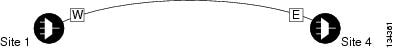
Step 2![]() Verify that the topology where you plan to run the ETR_CLO or ISC service can support the service. The following topologies support ETR_CLO or ISC:
Verify that the topology where you plan to run the ETR_CLO or ISC service can support the service. The following topologies support ETR_CLO or ISC:
–![]() 40-MUX-C and 40-DMX-C/40-DMX-CE cards
40-MUX-C and 40-DMX-C/40-DMX-CE cards
–![]() 40-WSS-C/40-WSS-CE and 40-DMX-C/40-DMX-CE cards
40-WSS-C/40-WSS-CE and 40-DMX-C/40-DMX-CE cards
Figure 5-1 shows a single-span topology as displayed in Cisco TransportPlanner.
Figure 5-1 Single-Span Topology
–![]() 40-MUX-C and 40-DMX-C/40-DMX-CE cards
40-MUX-C and 40-DMX-C/40-DMX-CE cards
–![]() 40-WSS-C/40-WSS-CE and 40-DMX-C/40-DMX-CE cards
40-WSS-C/40-WSS-CE and 40-DMX-C/40-DMX-CE cards
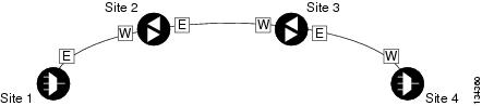
Line amplifiers can be installed between the terminal sites, but intermediate (traffic terminating) sites cannot be installed. Figure 5-2 shows a point-to-point topology as shown in Cisco TransportPlanner.
Figure 5-2 Point-to-Point Topology
–![]() 40-MUX-C and 40-DMX-C/40-DMX-CE cards
40-MUX-C and 40-DMX-C/40-DMX-CE cards
–![]() 40-WSS-C/40-WSS-CE and 40-DMX-C/40-DMX-CE cards
40-WSS-C/40-WSS-CE and 40-DMX-C/40-DMX-CE cards
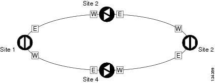
Line amplifiers can be installed between the hubs. Figure 5-3 shows two hub nodes with no line amplifier nodes installed. Figure 5-4 shows two hub nodes with line amplifier nodes installed.
Figure 5-3 Hubs with No Line Amplifiers
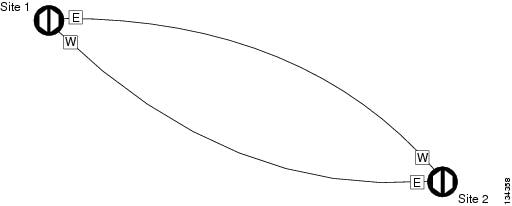
Figure 5-4 Hubs with Line Amplifiers
Step 3![]() Return to your originating procedure (NTP).
Return to your originating procedure (NTP).
DLP-G278 Provision the Optical Line Rate
This task provisions the line rate for TXP, MXP, GE_XP, 10GE_XP, GE_XPE, 10GE_XPE, ADM-10G, and OTU2_XP cards. |
|
| G277 Provision a Multirate PPM G274 Verify Topologies for ETR_CLO and ISC Services, if you are provisioning an ETR_CLO service. |
|
Note![]() The optical line rate for cards with single-rate PPMs is provisioned automatically when you complete the G277 Provision a Multirate PPM if the trunk port is out of service. If the optical line rate was provisioned automatically, you do not need to complete this task for the MXP_2.5G_10G, MXP_2.5G_10E, MXP_2.5G_10E_C, MXP_2.5G_10E_L, GE_XP, 10GE_XP, GE_XPE, 10GE_XPE, or OTU2_XP card. If the trunk port was in-service when you provisioned the PPM, complete this task to provision the optical line rate manually for those cards.
The optical line rate for cards with single-rate PPMs is provisioned automatically when you complete the G277 Provision a Multirate PPM if the trunk port is out of service. If the optical line rate was provisioned automatically, you do not need to complete this task for the MXP_2.5G_10G, MXP_2.5G_10E, MXP_2.5G_10E_C, MXP_2.5G_10E_L, GE_XP, 10GE_XP, GE_XPE, 10GE_XPE, or OTU2_XP card. If the trunk port was in-service when you provisioned the PPM, complete this task to provision the optical line rate manually for those cards.
Step 1![]() In node view (single-shelf mode) or shelf view (multishelf view), double-click the TXP, MXP, GE_XP, 10GE_XP, GE_XPE, 10GE_XPE, or OTU2_XP card where you want to provision PPM ports. If the data rate that you are provisioning is DV-6000, HDTV, ESCON, SDI/D1 Video, ISC-3 (all cards except the MXP_MR_10DME_C or MXP_MR_10DME_L), or ETR_CLO, complete the following steps. Otherwise, continue with Step 4.
In node view (single-shelf mode) or shelf view (multishelf view), double-click the TXP, MXP, GE_XP, 10GE_XP, GE_XPE, 10GE_XPE, or OTU2_XP card where you want to provision PPM ports. If the data rate that you are provisioning is DV-6000, HDTV, ESCON, SDI/D1 Video, ISC-3 (all cards except the MXP_MR_10DME_C or MXP_MR_10DME_L), or ETR_CLO, complete the following steps. Otherwise, continue with Step 4.
a.![]() Click the Provisioning > OTN > OTN Lines tabs.
Click the Provisioning > OTN > OTN Lines tabs.
b.![]() In the ITU-T G.709 OTN field for the respective PPM, choose Disable.
In the ITU-T G.709 OTN field for the respective PPM, choose Disable.
c.![]() In the FEC field for the respective PPM, choose Disable.
In the FEC field for the respective PPM, choose Disable.
Step 2![]() For the TXP_MR-10G card, click the Provisioning > Data Rate Selection tabs. For all other cards, go to Step 4 .
For the TXP_MR-10G card, click the Provisioning > Data Rate Selection tabs. For all other cards, go to Step 4 .
Step 3![]() In the Data Rate Selection area, click Create and choose the type of port from the drop-down list. The supported port types are SONET (including 10G Ethernet WAN Phy) and 10G Ethernet LAN Phy.
In the Data Rate Selection area, click Create and choose the type of port from the drop-down list. The supported port types are SONET (including 10G Ethernet WAN Phy) and 10G Ethernet LAN Phy.
Step 4![]() Click the Provisioning > Pluggable Port Modules tabs.
Click the Provisioning > Pluggable Port Modules tabs.
Step 5![]() In the Pluggable Ports area, click Create. The Create Port dialog box appears.
In the Pluggable Ports area, click Create. The Create Port dialog box appears.
Step 6![]() In the Create Port dialog box, complete the following:
In the Create Port dialog box, complete the following:
- Port—Choose the port and port number from the drop-down list. The first number indicates the PPM in the Pluggable Port Modules area, and the second number indicates the port number on the PPM. For example, the first PPM with one port appears as 1-1 and the second PPM with one port appears as 2-1. The PPM number can be 1 to 4, but the port number is always 1.
- Port Type—Choose the type of port from the drop-down list. The port type list displays the supported port rates on your PPM. See Table 5-3 for definitions of the supported rates on the TXP, MXP, GE_XP, 10GE_XP, GE_XPE, 10GE_XPE, or OTU2_XP card.
Step 7![]() Click OK. The row in the Pluggable Ports area turns white if the physical SFP is installed and light blue if the SFP is not installed.
Click OK. The row in the Pluggable Ports area turns white if the physical SFP is installed and light blue if the SFP is not installed.
If the optical parameter values differ from the NE Default settings, change the port state to In-Service (for ANSI) or Unlocked (for ETSI) to synchronize the values with the NE Default settings.
Step 8![]() Repeat Steps 5 through 7 to configure the rest of the port rates as needed.
Repeat Steps 5 through 7 to configure the rest of the port rates as needed.
|
|
|
|---|---|
|
|
|
|
TXP_MR_10G2 |
|
|
|
If the port mode is FC_GE_ISC:
|
|
Note If you have an OTU2 signal in which the OPU2 has been generated by multiplexing four ODU1 signals, choose SONET as the port rate. This allows the OTU2 signal to be transported transparently in standard or E-FEC regenerator configuration. |
|
1.Automatically provisioned when the PPM is created if the trunk port is out of service. |
Step 9![]() Return to your originating procedure (NTP).
Return to your originating procedure (NTP).
This task deletes PPM provisioning for SFPs or XFPs installed on TXP, MXP, GE_XP, 10GE_XP, GE_XPE, 10GE_XPE, ADM-10G, or OTU2_XP card. |
|
Note![]() Before deleting a PPM, delete the PPM fromthe provisioning pane.
Before deleting a PPM, delete the PPM fromthe provisioning pane.
Note![]() This task does not apply to the TXP_MR_10G card. To change the TXP_MR_10G data rate, complete the G365 Provision the TXP_MR_10G Data Rate.
This task does not apply to the TXP_MR_10G card. To change the TXP_MR_10G data rate, complete the G365 Provision the TXP_MR_10G Data Rate.
Note![]() You cannot delete a PPM if the TXP, MXP, GE_XP, 10GE_XP, GE_XPE, 10GE_XPE, or ADM-10G card is part of a regenerator group. For OTU2_XP card, you cannot delete a PPM if the card configuration is in Standard Regen or Enhanced FEC mode.
You cannot delete a PPM if the TXP, MXP, GE_XP, 10GE_XP, GE_XPE, 10GE_XPE, or ADM-10G card is part of a regenerator group. For OTU2_XP card, you cannot delete a PPM if the card configuration is in Standard Regen or Enhanced FEC mode.
Step 1![]() In node view (single-shelf mode) or shelf view (multishelf view), double-click the TXP, MXP, GE_XP, 10GE_XP, GE_XPE, 10GE_XPE, ADM-10G, or OTU2_XP card where you want to delete PPM settings.
In node view (single-shelf mode) or shelf view (multishelf view), double-click the TXP, MXP, GE_XP, 10GE_XP, GE_XPE, 10GE_XPE, ADM-10G, or OTU2_XP card where you want to delete PPM settings.
Step 2![]() Verify that the PPM port Service State is OOS,DSBLD. If the PPM port is OOS,DSBLD, go to Step 3 . If it is not OOS,DSBLD, follow the tasks in G128 Manage Pluggable Port Modules, to change the Service State of the PPM port to OOS,DSBLD.
Verify that the PPM port Service State is OOS,DSBLD. If the PPM port is OOS,DSBLD, go to Step 3 . If it is not OOS,DSBLD, follow the tasks in G128 Manage Pluggable Port Modules, to change the Service State of the PPM port to OOS,DSBLD.
Step 3![]() Click the Provisioning > Pluggable Port Modules tabs.
Click the Provisioning > Pluggable Port Modules tabs.
Step 4![]() To delete a PPM and the associated ports:
To delete a PPM and the associated ports:
a.![]() In the Pluggable Port Modules area, click the PPM that you want to delete. The highlight changes to dark blue.
In the Pluggable Port Modules area, click the PPM that you want to delete. The highlight changes to dark blue.
b.![]() Click Delete. The Delete PPM dialog box appears.
Click Delete. The Delete PPM dialog box appears.
c.![]() Click Yes. The PPM provisioning is removed from the Pluggable Port Modules area and the Pluggable Ports area.
Click Yes. The PPM provisioning is removed from the Pluggable Port Modules area and the Pluggable Ports area.
Note![]() You cannot delete a PPM until its port is in the OOS,DSBLD state. You cannot delete a client port if the client is in the In Service and Normal (IS-NR) (ANSI) or Unlocked-enabled (ETSI) service state, is in a protection group, has a generic communications channel (GCC) or data communications channel (DCC), is a timing source, has circuits or overhead circuits, or transports Link Management Protocol channels or links. You can delete a client port (except the last port) if the trunk port is in service and the client port is in the OOS,DSBLD (ANSI) or Locked-enabled,disabled (ETSI) service state. You can delete the last client port only if the trunk port is in a OOS,DSBLD (ANSI) or Locked-enabled,disabled (ETSI) service state for all cards except the MXP_MR_2.5G, MXPP_MR_2.5G, MXP_MR_10DME_C, and MXP_MR_10DME_L cards. For more information about port states, refer to the “Administrative and Service States” appendix in the Cisco ONS 15454 DWDM Reference Manual.
You cannot delete a PPM until its port is in the OOS,DSBLD state. You cannot delete a client port if the client is in the In Service and Normal (IS-NR) (ANSI) or Unlocked-enabled (ETSI) service state, is in a protection group, has a generic communications channel (GCC) or data communications channel (DCC), is a timing source, has circuits or overhead circuits, or transports Link Management Protocol channels or links. You can delete a client port (except the last port) if the trunk port is in service and the client port is in the OOS,DSBLD (ANSI) or Locked-enabled,disabled (ETSI) service state. You can delete the last client port only if the trunk port is in a OOS,DSBLD (ANSI) or Locked-enabled,disabled (ETSI) service state for all cards except the MXP_MR_2.5G, MXPP_MR_2.5G, MXP_MR_10DME_C, and MXP_MR_10DME_L cards. For more information about port states, refer to the “Administrative and Service States” appendix in the Cisco ONS 15454 DWDM Reference Manual.
Step 5![]() Verify that the PPM provisioning is deleted:
Verify that the PPM provisioning is deleted:
- In the TXP, MXP, GE_XP, 10GE_XP, GE_XPE, 10GE_XPE, ADM-10G, or OTU2_XP card view, CTC shows an empty port after the PPM is deleted.
- If the SFP or XFP is physically present when you delete the PPM provisioning, CTC transitions to the deleted state, the ports (if any) are deleted, and the PPM is represented as a gray graphic in CTC. The SFP or XFP can be provisioned again in CTC, or the equipment can be removed. If the equipment is removed, the graphic disappears.
Step 6![]() If you need to remove the PPM hardware (the SFP or XFP), complete the G64 Remove an SFP or XFP.
If you need to remove the PPM hardware (the SFP or XFP), complete the G64 Remove an SFP or XFP.
Step 7![]() Return to your originating procedure (NTP).
Return to your originating procedure (NTP).
NTP-G33 Create a Y-Cable Protection Group
Note![]() Y-cable protection is available for the GE_XP, 10GE_XP, GE_XPE, and 10GE_XPE cards when they are provisioned in 10GE MXP, 20GE MXP, or 10GE TXP mode. Y-cable protection cannot be provisioned for the GE_XP, 10GE_XP, GE_XPE, and 10GE_XPE cards when they are provisioned in L2-over-DWDM mode. Y-cable protection is available for the OTU2_XP card when it is provisioned in the TXP card mode.
Y-cable protection is available for the GE_XP, 10GE_XP, GE_XPE, and 10GE_XPE cards when they are provisioned in 10GE MXP, 20GE MXP, or 10GE TXP mode. Y-cable protection cannot be provisioned for the GE_XP, 10GE_XP, GE_XPE, and 10GE_XPE cards when they are provisioned in L2-over-DWDM mode. Y-cable protection is available for the OTU2_XP card when it is provisioned in the TXP card mode.
Note![]() If you are provisioning Y-cable protection for GE_XP, 10GE_XP, GE_XPE, and 10GE_XPE cards, the Ethernet mode must be set to 1000 and 10000 Mbps respectively. To provision the Ethernet mode, see the G380 Provision the GE_XP, 10GE_XP, GE_XPE, and 10GE_XPE Card Ethernet Settings.
If you are provisioning Y-cable protection for GE_XP, 10GE_XP, GE_XPE, and 10GE_XPE cards, the Ethernet mode must be set to 1000 and 10000 Mbps respectively. To provision the Ethernet mode, see the G380 Provision the GE_XP, 10GE_XP, GE_XPE, and 10GE_XPE Card Ethernet Settings.
Note![]() There is a traffic hit of upto a couple hundred milliseconds on the MXP_MR_2.5G and MXP_MR_10DME cards in Y-cable configuration when a fiber cut or SFP failure occurs on one of the client ports.
There is a traffic hit of upto a couple hundred milliseconds on the MXP_MR_2.5G and MXP_MR_10DME cards in Y-cable configuration when a fiber cut or SFP failure occurs on one of the client ports.
Note![]() For SONET or SDH payloads, Loss of Pointer Path (LOP-P) alarms can occur on a split signal if the ports are not in a Y-cable protection group.
For SONET or SDH payloads, Loss of Pointer Path (LOP-P) alarms can occur on a split signal if the ports are not in a Y-cable protection group.
Step 1![]() View the Cisco TransportPlanner Traffic Matrix (see Table 3-1) for your site. Verify the TXP, MXP, GE_XP, 10GE_XP, GE_XPE, 10GE_XPE, or OTU2_XP cards that need Y-cable protection groups. (Cards requiring Y-cable protection are indicated with “Y-Cable” in the Traffic Matrix table Protection Type column. Refer to the Cisco TransportPlanner DWDM Operations Guide for more information.)
View the Cisco TransportPlanner Traffic Matrix (see Table 3-1) for your site. Verify the TXP, MXP, GE_XP, 10GE_XP, GE_XPE, 10GE_XPE, or OTU2_XP cards that need Y-cable protection groups. (Cards requiring Y-cable protection are indicated with “Y-Cable” in the Traffic Matrix table Protection Type column. Refer to the Cisco TransportPlanner DWDM Operations Guide for more information.)
Step 2![]() Verify that the TXP, MXP, GE_XP, 10GE_XP, GE_XPE, 10GE_XPE, or OTU2_XP cards are installed according to the requirements specified in Table 3-6. Table 5-4 lists the protection types available in the ONS 15454 for DWDM client cards.
Verify that the TXP, MXP, GE_XP, 10GE_XP, GE_XPE, 10GE_XPE, or OTU2_XP cards are installed according to the requirements specified in Table 3-6. Table 5-4 lists the protection types available in the ONS 15454 for DWDM client cards.
|
|
|
|
|---|---|---|
| GE_XP3 10GE_XP4 |
Pairs a working transponder or muxponder card or port with a protect transponder or muxponder card or port. The protect port must be on a different card than the working port and it must be the same card type as the working port. The working and protect port numbers must be the same, that is, Port 1 can only protect Port 1, Port 2 can only protect Port 2, and so on. |
|
A splitter protection group is automatically created when a TXPP_MR_2.5G or MXPP_MR_2.5G card is installed. You can edit the splitter protection group name. |
||
A splitter protection group is configurable for the OTU2_XP card. You can create a splitter protection group on Ports 3 and 4 of the OTU2_XP card using the G199 Create a Splitter Protection Group for the OTU2_XP Card. |
||
In the Layer 2 (L2) card mode 1+1 protection is provided to protect the card against client port and card failure. |
|
|
Step 3![]() Verify that pluggable ports are provisioned for the same payload and payload rate on the TXP, MXP, GE_XP, 10GE_XP, GE_XPE, 10GE_XPE, or OTU2_XP cards where you will create the Y-cable protection group:
Verify that pluggable ports are provisioned for the same payload and payload rate on the TXP, MXP, GE_XP, 10GE_XP, GE_XPE, 10GE_XPE, or OTU2_XP cards where you will create the Y-cable protection group:
a.![]() Display the TXP, MXP, GE_XP, 10GE_XP, GE_XPE, 10GE_XPE, or OTU2_XP card in card view.
Display the TXP, MXP, GE_XP, 10GE_XP, GE_XPE, 10GE_XPE, or OTU2_XP card in card view.
b.![]() Click the Provisioning > Pluggable Port Module tab.
Click the Provisioning > Pluggable Port Module tab.
c.![]() Verify that a pluggable port is provisioned in the Pluggable Port Module area, and the payload type and rate is provisioned for it in the Pluggable Ports area. If they are not the same, for example, if the pluggable port and rate are not the same, you must either delete the provisioned rate and create a new rate to match using the G273 Preprovision an SFP or XFP Slot or replace the pluggable port (SFP or XFP) using the G64 Remove an SFP or XFP.
Verify that a pluggable port is provisioned in the Pluggable Port Module area, and the payload type and rate is provisioned for it in the Pluggable Ports area. If they are not the same, for example, if the pluggable port and rate are not the same, you must either delete the provisioned rate and create a new rate to match using the G273 Preprovision an SFP or XFP Slot or replace the pluggable port (SFP or XFP) using the G64 Remove an SFP or XFP.
Step 4![]() In node view (single-shelf mode) or shelf view (multishelf mode), click the Provisioning > Protection tabs.
In node view (single-shelf mode) or shelf view (multishelf mode), click the Provisioning > Protection tabs.
Step 5![]() In the Protection Groups area, click Create.
In the Protection Groups area, click Create.
Step 6![]() In the Create Protection Group dialog box, enter the following:
In the Create Protection Group dialog box, enter the following:
- Name—Type a name for the protection group. The name can have up to 32 alphanumeric (a-z, A-Z, 0-9) characters. Special characters are permitted. For TL1 compatibility, do not use question mark (?), backslash (\), or double quote (“) characters.
- Type—Choose Y Cable from the drop-down list.
- Protect Port—From the drop-down list, choose the port that will be the standby or protection port to the active port. The list displays the available transponder or muxponder ports. If transponder or muxponder cards are not installed, no ports appear in the drop-down list.
After you choose the protect port, a list of available working ports appear in the Available Ports list, as shown in Figure 5-5. If no cards are available, no ports appear. If this occurs, you can not complete this task until you install the physical cards or preprovision the ONS 15454 slots using the G353 Preprovision a Single Slot.
Figure 5-5 Creating a Y-Cable Protection Group
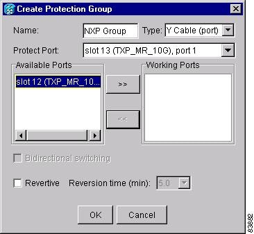
Step 7![]() From the Available Ports list, select the port that will be protected by the port you selected in Protect Ports. Click the top arrow button to move the port to the Working Ports list.
From the Available Ports list, select the port that will be protected by the port you selected in Protect Ports. Click the top arrow button to move the port to the Working Ports list.
Step 8![]() Complete the remaining fields:
Complete the remaining fields:
- Revertive—Check this check box if you want traffic to revert to the working port after failure conditions remain corrected for the amount of time entered in the Reversion Time field.
- Reversion time—If Revertive is checked, select a reversion time from the drop-down list. The range is 0.5 to 12.0 minutes. The default is 5.0 minutes. Reversion time is the amount of time that will elapse before the traffic reverts to the working card. The reversion timer starts after conditions causing the switch are cleared.
Note The Bidirectional switching option is available for Y-cable protection groups only in the following cases:
- On the MXP_MR_10DME card when ISC3_PEER_1G/ISC3_PEER_2G is the client payload.
- On the MXP_MR_10DME and MXP_MR_2.5G cards when Fibre Channel is the client payload. In this case Bidirectional switching is:
–![]() Automatically enabled when Distance Extension is enabled.
Automatically enabled when Distance Extension is enabled.
–![]() Automatically disabled when Distance Extension is disabled.
Automatically disabled when Distance Extension is disabled.
The Bidirectional switching option is available for all SONET and SDH 1+1 protection groups.
Step 10![]() Repeat this procedure for every Y-cable protection group indicated in the Cisco TransportPlanner Traffic Matrix.
Repeat this procedure for every Y-cable protection group indicated in the Cisco TransportPlanner Traffic Matrix.
Stop. You have completed this procedure.
NTP-G199 Create a Splitter Protection Group for the OTU2_XP Card
Note![]() A splitter protection group is automatically created when a TXPP_MR_2.5G, MXPP_MR_2.5G, or PSM card is installed. You can edit the splitter protection group name for these cards. The splitter protection group is deleted when you delete the TXPP_MR_2.5G, MXPP_MR_2.5G, or PSM card.
A splitter protection group is automatically created when a TXPP_MR_2.5G, MXPP_MR_2.5G, or PSM card is installed. You can edit the splitter protection group name for these cards. The splitter protection group is deleted when you delete the TXPP_MR_2.5G, MXPP_MR_2.5G, or PSM card.
Note![]() Splitter protection is available for the OTU2_XP card when it is provisioned in Transponder configuration only. In a splitter-protected Transponder configuration, Port 1 is the client port, Port 3 is the working trunk port, and Port 4 is the standby trunk port.
Splitter protection is available for the OTU2_XP card when it is provisioned in Transponder configuration only. In a splitter-protected Transponder configuration, Port 1 is the client port, Port 3 is the working trunk port, and Port 4 is the standby trunk port.
Note![]() For SONET or SDH payloads, Loss of Pointer Path (LOP-P) alarms can occur on a split signal if the ports are not in a splitter protection group.
For SONET or SDH payloads, Loss of Pointer Path (LOP-P) alarms can occur on a split signal if the ports are not in a splitter protection group.
Step 1![]() View the Cisco TransportPlanner Traffic Matrix (see Table 3-1) for your site. Verify which OTU2_XP card needs a splitter protection group. (Cards requiring splitter protection are indicated with “Splitter” in the Traffic Matrix table Protection Type column. Refer to the Cisco TransportPlanner DWDM Operations Guide for more information.)
View the Cisco TransportPlanner Traffic Matrix (see Table 3-1) for your site. Verify which OTU2_XP card needs a splitter protection group. (Cards requiring splitter protection are indicated with “Splitter” in the Traffic Matrix table Protection Type column. Refer to the Cisco TransportPlanner DWDM Operations Guide for more information.)
Step 2![]() Verify that the OTU2_XP card is installed according to the requirements specified in Table 3-6.
Verify that the OTU2_XP card is installed according to the requirements specified in Table 3-6.
Step 3![]() Verify that the pluggable port (SFP or XFP) slot is provisioned for the same payload rate as the pluggable port on the OTU2_XP card where you will create the splitter protection group:
Verify that the pluggable port (SFP or XFP) slot is provisioned for the same payload rate as the pluggable port on the OTU2_XP card where you will create the splitter protection group:
a.![]() Display the OTU2_XP card in card view.
Display the OTU2_XP card in card view.
b.![]() Click the Provisioning > Pluggable Port Module tabs.
Click the Provisioning > Pluggable Port Module tabs.
c.![]() Verify that a pluggable port (SFP or XFP) slot is provisioned in the Pluggable Port Module area, and that the payload rate of the pluggable port (SFP or XFP) slot is same as the payload rate of the pluggable port on the OTU2_XP card provisioned in the Pluggable Ports area. If they are not the same, you must either delete the provisioned rate and create a new rate to match using the G273 Preprovision an SFP or XFP Slot or replace the pluggable port (SFP or XFP) using the G64 Remove an SFP or XFP.
Verify that a pluggable port (SFP or XFP) slot is provisioned in the Pluggable Port Module area, and that the payload rate of the pluggable port (SFP or XFP) slot is same as the payload rate of the pluggable port on the OTU2_XP card provisioned in the Pluggable Ports area. If they are not the same, you must either delete the provisioned rate and create a new rate to match using the G273 Preprovision an SFP or XFP Slot or replace the pluggable port (SFP or XFP) using the G64 Remove an SFP or XFP.
Step 4![]() In node view (single-shelf mode) or shelf view (multishelf view), click the Provisioning > Protection tabs.
In node view (single-shelf mode) or shelf view (multishelf view), click the Provisioning > Protection tabs.
Step 5![]() In the Protection Groups area, click Create.
In the Protection Groups area, click Create.
Step 6![]() In the Create Protection Group dialog box, enter the following:
In the Create Protection Group dialog box, enter the following:
- Name—Type a name for the protection group. The name can have up to 32 alphanumeric (a-z, A-Z, 0-9) characters. Special characters are permitted. For TL1 compatibility, do not use question mark (?), backslash (\), or double quote (“) characters.
- Type—Choose Splitter from the drop-down list.
- Protect Card—From the drop-down list, choose the port that will be the standby or protection port to the active port. The list displays the available OTU2_XP ports. If transponder or muxponder cards are not installed or if the trunk ports of the card are part of a regenerator group, no ports appear in the drop-down list.
After you choose the protect port, a list of available working ports appear in the Available Cards list, as shown in Figure 5-6. If no cards are available, no ports appear. If this occurs, you cannot complete this task until you install the physical cards or preprovision the ONS 15454 slots using the G353 Preprovision a Single Slot.
Figure 5-6 Creating a Splitter Protection Group
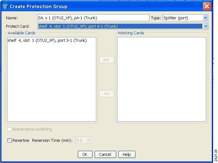
Step 7![]() From the Available Cards list, select the port that will be protected by the port you selected in Protect Cards. Click the top arrow button to move the port to the Working Cards list.
From the Available Cards list, select the port that will be protected by the port you selected in Protect Cards. Click the top arrow button to move the port to the Working Cards list.
Step 8![]() Complete the remaining fields:
Complete the remaining fields:
- Revertive—Check this check box if you want traffic to revert to the working port after failure conditions remain corrected for the amount of time entered in the Reversion Time field.
- Reversion time—If Revertive is checked, select a reversion time from the drop-down list. The range is 0.5 to 12.0 minutes. The default is 5.0 minutes. Reversion time is the amount of time that will elapse before the traffic reverts to the working card. The reversion timer starts after conditions causing the switch are cleared.
Note![]() The Bidirectional Switching option is not applicable for splitter protection groups.
The Bidirectional Switching option is not applicable for splitter protection groups.
Step 10![]() Repeat this procedure for every splitter protection group indicated in the Cisco TransportPlanner Traffic Matrix.
Repeat this procedure for every splitter protection group indicated in the Cisco TransportPlanner Traffic Matrix.
Stop. You have completed this procedure.
NTP-G198 Create 1+1 Protection for GE_XP, 10GE_XP, GE_XPE, or 10GE_XPE Cards
Step 1![]() Complete the G46 Log into CTC at the node where you want to protect the card against client port and card failure. If you are already logged in, continue with Step 2.
Complete the G46 Log into CTC at the node where you want to protect the card against client port and card failure. If you are already logged in, continue with Step 2.
Step 2![]() Verify that the GE_XP, 10GE_XP, GE_XPE, or 10GE_XPE card is installed according to the requirements specified in Table 3-6.
Verify that the GE_XP, 10GE_XP, GE_XPE, or 10GE_XPE card is installed according to the requirements specified in Table 3-6.
Step 3![]() Complete the G354 Create an Internal Patchcord Manually by selecting the Trunk to Trunk (L2) option, at the trunk port where you want to create 1+1 protection.
Complete the G354 Create an Internal Patchcord Manually by selecting the Trunk to Trunk (L2) option, at the trunk port where you want to create 1+1 protection.
Step 4![]() Complete the G461 Create a 1+1 Protection Group for GE_XP, 10GE_XP, GE_XPE, or 10GE_XPE Cards to create a protection group.
Complete the G461 Create a 1+1 Protection Group for GE_XP, 10GE_XP, GE_XPE, or 10GE_XPE Cards to create a protection group.
Step 5![]() Configure the standby port behavior, by setting the Protection Action to None or Squelch. For detailed information on how to configure the standby port behavior, see the, G380 Provision the GE_XP, 10GE_XP, GE_XPE, and 10GE_XPE Card Ethernet Settings.
Configure the standby port behavior, by setting the Protection Action to None or Squelch. For detailed information on how to configure the standby port behavior, see the, G380 Provision the GE_XP, 10GE_XP, GE_XPE, and 10GE_XPE Card Ethernet Settings.
Note![]() Do not enable squelch in a 1 + 1 protection group, if the ONS-SE-ZE-EL SFP is used in the protection group and is connected to the peer via the parallel cable (not Y-cable).
Do not enable squelch in a 1 + 1 protection group, if the ONS-SE-ZE-EL SFP is used in the protection group and is connected to the peer via the parallel cable (not Y-cable).
Note![]() When you configure L2 1 + 1 protection on 10GE_XP and 10GE_XPE cards, set the Protection Action to None on the client ports. Setting the Protection Action as Squelch results in unexpected switching behavior.
When you configure L2 1 + 1 protection on 10GE_XP and 10GE_XPE cards, set the Protection Action to None on the client ports. Setting the Protection Action as Squelch results in unexpected switching behavior.
Step 6![]() Configure the standby and active port speed, by setting the mode parameter to Auto or 1000 or any other values. For detailed information on how to configure the standby port behavior, see the G380 Provision the GE_XP, 10GE_XP, GE_XPE, and 10GE_XPE Card Ethernet Settings.
Configure the standby and active port speed, by setting the mode parameter to Auto or 1000 or any other values. For detailed information on how to configure the standby port behavior, see the G380 Provision the GE_XP, 10GE_XP, GE_XPE, and 10GE_XPE Card Ethernet Settings.
Stop. You have completed this procedure.
DLP-G461 Create a 1+1 Protection Group for GE_XP, 10GE_XP, GE_XPE, or 10GE_XPE Cards
This procedure creates a 1+1 protection group for GE_XP, 10GE_XP, GE_XPE, or 10GE_XPE slots where internal patchcords were created. |
|
Step 1![]() In node view (single-shelf mode) or multishelf view (multishelf mode), click the Provisioning > Protection tabs.
In node view (single-shelf mode) or multishelf view (multishelf mode), click the Provisioning > Protection tabs.
Step 2![]() In the Protection Groups area, click Create.
In the Protection Groups area, click Create.
Step 3![]() In the Create Protection Group dialog box, enter the following:
In the Create Protection Group dialog box, enter the following:
- Name—Type a name for the protection group. The name can have up to 32 alphanumeric (a-z, A-Z, 0-9) characters. Special characters are permitted. For TL1 compatibility, do not use question mark (?), backslash (\), or double quote (“) characters.
- Type—Choose L2 1+1 (port) from the drop-down list.
- Protect Port—From the drop-down list, choose the port that will be the standby or protection port for the active port. The list displays the available transponder or muxponder ports. If transponder or muxponder cards are not installed, no ports appear in the drop-down list.
After you choose the protect port, a list of available working ports appear in the Available Ports list, as shown in Figure 5-7. If no cards are available, no ports appear. If this occurs, you cannot complete this task until you install the physical cards or preprovision the ONS 15454 slots using the G353 Preprovision a Single Slot.
Figure 5-7 Creating a 1+1 Protection Group
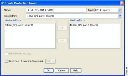
Step 4![]() From the Available Ports list, select the port that will be protected by the port you selected in the Protected Port drop-down list. Click the top arrow button to move the port to the Working Ports list.
From the Available Ports list, select the port that will be protected by the port you selected in the Protected Port drop-down list. Click the top arrow button to move the port to the Working Ports list.
Step 5![]() Complete the remaining fields:
Complete the remaining fields:
- Revertive—Check this check box if you want traffic to revert to the working port after failure conditions remain corrected for the amount of time entered in the Reversion Time field.
- Reversion time—If Revertive is checked, select a reversion time from the drop-down list. The range is 0.5 to 12.0 minutes. The default is 5.0 minutes. Reversion time is the amount of time that will elapse before the traffic reverts to the working card. The reversion timer starts after conditions causing the switch are cleared.
The bidirectional switching option is available for SONET and SDH 1+1 protection groups.
Step 7![]() Repeat this procedure for every 1+1 protection group indicated in the Cisco TransportPlanner Traffic Matrix.
Repeat this procedure for every 1+1 protection group indicated in the Cisco TransportPlanner Traffic Matrix.
Step 8![]() Return to your originating procedure (NTP).
Return to your originating procedure (NTP).
NTP-G98 Provision the 2.5G Multirate Transponder Card Line Settings and PM Parameter Thresholds
This procedure changes the line and threshold settings for TXP_MR_2.5G and TXPP_MR_2.5G transponder cards. |
|
G179 Install the TXP, MXP, GE_XP, 10GE_XP, GE_XPE, 10GE_XPE, ADM-10G, and OTU2_XP Cards G277 Provision a Multirate PPM (if necessary) G278 Provision the Optical Line Rate (if necessary) |
|
Step 1![]() Complete the G46 Log into CTC at the node where you want to change the transponder card settings. If you are already logged in, continue with Step 2.
Complete the G46 Log into CTC at the node where you want to change the transponder card settings. If you are already logged in, continue with Step 2.
Step 2![]() As needed, complete the G103 Back Up the Database to preserve the existing transmission settings.
As needed, complete the G103 Back Up the Database to preserve the existing transmission settings.
Step 3![]() Perform any of the following tasks as needed:
Perform any of the following tasks as needed:
- G229 Change the 2.5G Multirate Transponder Card Settings
- G230 Change the 2.5G Multirate Transponder Line Settings
- G231 Change the 2.5G Multirate Transponder Line Section Trace Settings
- G232 Change the 2.5G Multirate Transponder SONET or SDH Line Threshold Settings
- G320 Change the 2.5G Multirate Transponder Line RMON Thresholds for 1G Ethernet or 1G FC/FICON Payloads
- G305 Provision the 2.5G Multirate Transponder Trunk Port Alarm and TCA Thresholds
- G306 Provision the 2.5G Multirate Transponder Client Port Alarm and TCA Thresholds
- G234 Change the 2.5G Multirate Transponder OTN Settings
- G367 Change the 2.5G Multirate Transponder Trunk Wavelength Settings
Stop. You have completed this procedure.
DLP-G229 Change the 2.5G Multirate Transponder Card Settings
This task changes the card settings for TXP_MR_2.5G and TXPP_MR_2.5G transponder cards. |
|
Step 1![]() In node view (single-shelf mode) or shelf view (multishelf view), double-click the TXP_MR_2.5G or TXPP_MR_2.5G card where you want to change the card settings.
In node view (single-shelf mode) or shelf view (multishelf view), double-click the TXP_MR_2.5G or TXPP_MR_2.5G card where you want to change the card settings.
Step 2![]() Click the Provisioning > Card tabs.
Click the Provisioning > Card tabs.
Step 3![]() Modify any of the settings described in Table 5-5 .
Modify any of the settings described in Table 5-5 .
Note![]() The Card subtab Framing Type and Tunable Wavelengths fields are display-only. Framing Type shows the card framing type, either SONET or SDH, depending on whether the card is installed in an ANSI or ETSI chassis. The Tunable Wavelengths field shows the tunable wavelengths for the physical TXP_MR_2.5G or TXPP_MR_2.5G that is installed.
The Card subtab Framing Type and Tunable Wavelengths fields are display-only. Framing Type shows the card framing type, either SONET or SDH, depending on whether the card is installed in an ANSI or ETSI chassis. The Tunable Wavelengths field shows the tunable wavelengths for the physical TXP_MR_2.5G or TXPP_MR_2.5G that is installed.
Step 5![]() Return to your originating procedure (NTP).
Return to your originating procedure (NTP).
DLP-G230 Change the 2.5G Multirate Transponder Line Settings
This task changes the line settings for the client port of the TXP_MR_2.5G and TXPP_MR_2.5G transponder cards. |
|
Step 1![]() In node view (single-shelf mode) or shelf view (multishelf view), double-click the TXP_MR_2.5G or TXPP_MR_2.5G card where you want to change the line settings.
In node view (single-shelf mode) or shelf view (multishelf view), double-click the TXP_MR_2.5G or TXPP_MR_2.5G card where you want to change the line settings.
Step 2![]() Click the Provisioning > Line > SONET tabs.
Click the Provisioning > Line > SONET tabs.
Step 3![]() Modify any of the settings described in Table 5-6 .
Modify any of the settings described in Table 5-6 .
Note![]() The 2.5G multirate transponder trunk settings are provisioned in the G305 Provision the 2.5G Multirate Transponder Trunk Port Alarm and TCA Thresholds.
The 2.5G multirate transponder trunk settings are provisioned in the G305 Provision the 2.5G Multirate Transponder Trunk Port Alarm and TCA Thresholds.
|
|
|
|
|---|---|---|
The user can assign a logical name for each of the ports shown by filling in this field. |
User-defined. Name can be up to 32 alphanumeric/ special characters. Blank by default. See the G104 Assign a Name to a Port. |
|
Sets the port service state unless network conditions prevent the change. For more information about administrative states, refer to the “Administrative and Service States” appendix in the Cisco ONS 15454 DWDM Reference Manual. |
||
(Display only) Identifies the autonomously generated state that gives the overall condition of the port. Service states appear in the format: Primary State-Primary State Qualifier, Secondary State. For more information about service states, refer to the “Administrative and Service States” appendix in the Cisco ONS 15454 DWDM Reference Manual. |
||
(OC-N and STM-N payloads only) Sets the signal fail bit error rate. |
||
(OC-N and STM-N payloads only) Sets the signal degrade bit error rate. |
||
|
||
(OC-N and STM-N payloads only) Sets the automatic in-service soak period. |
||
Step 5![]() Return to your originating procedure (NTP).
Return to your originating procedure (NTP).
DLP-G231 Change the 2.5G Multirate Transponder Line Section Trace Settings
This task changes the section trace settings for TXP_MR_2.5G and TXPP_MR_2.5G transponder cards. |
|
Note![]() This task only applies to SONET services.
This task only applies to SONET services.
Step 1![]() In node view (single-shelf mode) or shelf view (multishelf view), double-click the TXP_MR_2.5G or TXPP_MR_2.5G card where you want to change the section trace settings.
In node view (single-shelf mode) or shelf view (multishelf view), double-click the TXP_MR_2.5G or TXPP_MR_2.5G card where you want to change the section trace settings.
Step 2![]() Click the Provisioning > Line > Section Trace tabs.
Click the Provisioning > Line > Section Trace tabs.
Step 3![]() Modify any of the settings described in Table 5-7 .
Modify any of the settings described in Table 5-7 .
Step 5![]() Return to your originating procedure (NTP).
Return to your originating procedure (NTP).
DLP-G367 Change the 2.5G Multirate Transponder Trunk Wavelength Settings
This task changes the trunk wavelength settings for the TXP_MR_2.5G and TXPP_MR_2.5G cards. |
|
Step 1![]() In node view (single-shelf mode) or shelf view (multishelf view), double-click the TXP_MR_2.5G or TXPP_MR_2.5G card where you want to change the trunk wavelength settings.
In node view (single-shelf mode) or shelf view (multishelf view), double-click the TXP_MR_2.5G or TXPP_MR_2.5G card where you want to change the trunk wavelength settings.
Step 2![]() Click the Provisioning > Line > Wavelength Trunk Settings tabs.
Click the Provisioning > Line > Wavelength Trunk Settings tabs.
Step 3![]() Modify any of the settings as described in Table 5-8 .
Modify any of the settings as described in Table 5-8 .
|
|
|
|
|---|---|---|
Step 5![]() Return to your originating procedure (NTP).
Return to your originating procedure (NTP).
DLP-G232 Change the 2.5G Multirate Transponder SONET or SDH Line Threshold Settings
This task changes the line threshold settings for TXP_MR_2.5G and TXPP_MR_2.5G transponder cards carrying OC-3/STM-1, OC-12/STM-4, and OC-48/STM-16 payloads. |
|
Step 1![]() In node view (single-shelf mode) or shelf view (multishelf view), double-click the TXP_MR_2.5G or TXPP_MR_2.5G card where you want to change the line threshold settings.
In node view (single-shelf mode) or shelf view (multishelf view), double-click the TXP_MR_2.5G or TXPP_MR_2.5G card where you want to change the line threshold settings.
Step 2![]() Click the Provisioning > Line Thresholds tabs.
Click the Provisioning > Line Thresholds tabs.
Note![]() You must modify Near End and Far End independently; 15 Min and 1 Day independently; and Line and Section independently. To do so, choose the appropriate radio button and click Refresh.
You must modify Near End and Far End independently; 15 Min and 1 Day independently; and Line and Section independently. To do so, choose the appropriate radio button and click Refresh.
Step 3![]() Modify any of the settings in Table 5-9 .
Modify any of the settings in Table 5-9 .
Note![]() Some parameters and options in Table 5-9 do not apply to all TXP_MR_2.5G or TXPP_MR_2.5G cards. If a parameter or option does not apply, that parameter or option does not appear in CTC.
Some parameters and options in Table 5-9 do not apply to all TXP_MR_2.5G or TXPP_MR_2.5G cards. If a parameter or option does not apply, that parameter or option does not appear in CTC.
Step 5![]() Return to your originating procedure (NTP).
Return to your originating procedure (NTP).
DLP-G320 Change the 2.5G Multirate Transponder Line RMON Thresholds for 1G Ethernet or 1G FC/FICON Payloads
This task changes the line remote monitoring (RMON) threshold settings for TXP_MR_2.5G and TXPP_MR_2.5G transponder cards carrying the 1G Ethernet or 1G FC/FICON payloads. |
|
Step 1![]() In card view, display the TXP_MR_2.5G or TXPP_MR_2.5G card where you want to change the line threshold settings.
In card view, display the TXP_MR_2.5G or TXPP_MR_2.5G card where you want to change the line threshold settings.
Step 2![]() Click the Provisioning > Line Thresholds > RMON Thresholds tabs.
Click the Provisioning > Line Thresholds > RMON Thresholds tabs.
Step 3![]() Click Create. The Create Threshold dialog box appears.
Click Create. The Create Threshold dialog box appears.
Step 4![]() From the Port drop-down list, choose the applicable port.
From the Port drop-down list, choose the applicable port.
Step 5![]() From the Variable drop-down list, choose an Ethernet variable. See Table 5-10 for a list of available Ethernet variables.
From the Variable drop-down list, choose an Ethernet variable. See Table 5-10 for a list of available Ethernet variables.
Step 6![]() From the Alarm Type drop-down list, indicate whether the event will be triggered by the rising threshold, the falling threshold, or both the rising and falling thresholds.
From the Alarm Type drop-down list, indicate whether the event will be triggered by the rising threshold, the falling threshold, or both the rising and falling thresholds.
Step 7![]() From the Sample Type drop-down list, choose either Relative or Absolute. Relative restricts the threshold to use the number of occurrences in the user-set sample period. Absolute sets the threshold to use the total number of occurrences, regardless of time period.
From the Sample Type drop-down list, choose either Relative or Absolute. Relative restricts the threshold to use the number of occurrences in the user-set sample period. Absolute sets the threshold to use the total number of occurrences, regardless of time period.
Step 8![]() Enter the appropriate number of seconds for the Sample Period.
Enter the appropriate number of seconds for the Sample Period.
Step 9![]() Enter the appropriate number of occurrences for the Rising Threshold.
Enter the appropriate number of occurrences for the Rising Threshold.
For a rising type of alarm, the measured value must move from below the falling threshold to above the rising threshold. For example, if a network is running below a rising threshold of 1000 collisions every 15 seconds and a problem causes 1001 collisions in 15 seconds, the excess occurrences trigger an alarm.
Step 10![]() Enter the appropriate number of occurrences in the Falling Threshold field. In most cases a falling threshold is set lower than the rising threshold.
Enter the appropriate number of occurrences in the Falling Threshold field. In most cases a falling threshold is set lower than the rising threshold.
A falling threshold is the counterpart to a rising threshold. When the number of occurrences is above the rising threshold and then drops below a falling threshold, it resets the rising threshold. For example, when the network problem that caused 1001 collisions in 15 seconds subsides and creates only 799 collisions in 15 seconds, occurrences fall below a falling threshold of 800 collisions. This resets the rising threshold so that if network collisions again spike over a 1000 per 15-second period, an event again triggers when the rising threshold is crossed. An event is triggered only the first time a rising threshold is exceeded (otherwise, a single network problem might cause a rising threshold to be exceeded multiple times and cause a flood of events).
Step 12![]() Return to your originating procedure (NTP).
Return to your originating procedure (NTP).
DLP-G305 Provision the 2.5G Multirate Transponder Trunk Port Alarm and TCA Thresholds
This task changes the TXP_MR_2.5G and TXPP_MR_2.5G trunk port alarm and threshold crossing alert (TCA) thresholds. |
|
Note![]() In this task, trunk port refers to Port 2 for TXP_MR_2.5G cards, and to Ports 2 and 3 for TXPP_MR_2.5G cards.
In this task, trunk port refers to Port 2 for TXP_MR_2.5G cards, and to Ports 2 and 3 for TXPP_MR_2.5G cards.
Step 1![]() In node view (single-shelf mode) or shelf view (multishelf view), double-click the TXP_MR_2.5G or TXPP_MR_2.5G card where you want to change the trunk port alarm and TCA settings.
In node view (single-shelf mode) or shelf view (multishelf view), double-click the TXP_MR_2.5G or TXPP_MR_2.5G card where you want to change the trunk port alarm and TCA settings.
Step 2![]() Click the Pluggable Port Modules tab. Under Pluggable Ports, record the Rate that is provisioned.
Click the Pluggable Port Modules tab. Under Pluggable Ports, record the Rate that is provisioned.
Step 3![]() Look up the rate in Table 5-11 and note whether it is 2R or 3R.
Look up the rate in Table 5-11 and note whether it is 2R or 3R.
|
|
|
|
|
|---|---|---|---|
3R5 |
|||
|
|
Step 4![]() Click the Provisioning > Optics Thresholds tabs.
Click the Provisioning > Optics Thresholds tabs.
Step 5![]() Under Types, verify that the TCA radio button is checked. If not, check it and click Refresh.
Under Types, verify that the TCA radio button is checked. If not, check it and click Refresh.
Step 6![]() Referring to Table 5-12 , verify the trunk port TCA thresholds for RX Power High and RX Power Low depending on whether the rate is 2R or 3R. Provision new thresholds as needed by double-clicking the threshold value you want to change, deleting it, entering a new value, and hitting Enter.
Referring to Table 5-12 , verify the trunk port TCA thresholds for RX Power High and RX Power Low depending on whether the rate is 2R or 3R. Provision new thresholds as needed by double-clicking the threshold value you want to change, deleting it, entering a new value, and hitting Enter.
Note![]() Do not modify the Laser Bias parameters.
Do not modify the Laser Bias parameters.
Note![]() You must modify 15 Min and 1 Day independently. To do so, choose the appropriate radio button and click Refresh.
You must modify 15 Min and 1 Day independently. To do so, choose the appropriate radio button and click Refresh.
|
|
|
|
|---|---|---|
Step 8![]() Under Types, click the Alarm radio button and click Refresh.
Under Types, click the Alarm radio button and click Refresh.
Step 9![]() Verify the trunk port Alarm thresholds for RX Power High is –7 dBm, and for RX Power Low is –26 dBm. Provision new thresholds as needed by double-clicking the threshold value you want to change, deleting it, entering a new value, and hitting Enter.
Verify the trunk port Alarm thresholds for RX Power High is –7 dBm, and for RX Power Low is –26 dBm. Provision new thresholds as needed by double-clicking the threshold value you want to change, deleting it, entering a new value, and hitting Enter.
Step 11![]() Return to your originating procedure (NTP).
Return to your originating procedure (NTP).
DLP-G306 Provision the 2.5G Multirate Transponder Client Port Alarm and TCA Thresholds
This task provisions the client port alarm and TCA thresholds for the TXP_MR_2.5G and TXPP_MR_2.5G cards. |
|
Step 1![]() In node view (single-shelf mode) or shelf view (multishelf view), double-click the TXP_MR_2.5G or TXPP_MR_2.5G card where you want to change the client port alarm and TCA settings.
In node view (single-shelf mode) or shelf view (multishelf view), double-click the TXP_MR_2.5G or TXPP_MR_2.5G card where you want to change the client port alarm and TCA settings.
Step 2![]() Click the Provisioning > Optics Thresholds tabs. The TCA thresholds are shown by default.
Click the Provisioning > Optics Thresholds tabs. The TCA thresholds are shown by default.
Step 3![]() Referring to Table 5-13 , verify the Port 1 (client) TCA thresholds for RX Power High, RX Power Low, TX Power High, and TX Power Low based on the client interface at the other end. Provision new thresholds as needed by double-clicking the threshold value you want to change, deleting it, entering a new value, and hitting Enter.
Referring to Table 5-13 , verify the Port 1 (client) TCA thresholds for RX Power High, RX Power Low, TX Power High, and TX Power Low based on the client interface at the other end. Provision new thresholds as needed by double-clicking the threshold value you want to change, deleting it, entering a new value, and hitting Enter.
Note![]() Do not modify the Laser Bias parameters.
Do not modify the Laser Bias parameters.
Note![]() You must modify 15 Min and 1 Day independently. To do so, choose the appropriate radio button and click Refresh.
You must modify 15 Min and 1 Day independently. To do so, choose the appropriate radio button and click Refresh.
Note![]() The hardware device that plugs into a TXP, MXP, GE_XP, 10GE_XP, GE_XPE, 10GE_XPE, or ADM-10G card faceplate to provide a fiber interface to the card is called a Small Form-factor Pluggable (SFP or XFP). In CTC, SFPs and XFPs are called pluggable port modules (PPMs). SFPs/XFPs are hot-swappable input/output devices that plug into a port to link the port with the fiber-optic network. Multirate PPMs have provisionable port rates and payloads. For more information about SFPs and XFPs, refer to the “Transponder and Muxponder Cards” chapter in the Cisco ONS 15454 DWDM Reference Manual.
The hardware device that plugs into a TXP, MXP, GE_XP, 10GE_XP, GE_XPE, 10GE_XPE, or ADM-10G card faceplate to provide a fiber interface to the card is called a Small Form-factor Pluggable (SFP or XFP). In CTC, SFPs and XFPs are called pluggable port modules (PPMs). SFPs/XFPs are hot-swappable input/output devices that plug into a port to link the port with the fiber-optic network. Multirate PPMs have provisionable port rates and payloads. For more information about SFPs and XFPs, refer to the “Transponder and Muxponder Cards” chapter in the Cisco ONS 15454 DWDM Reference Manual.
|
(by CTC) |
(SFP) |
Power Low |
Power High |
Power Low |
Power High |
|---|---|---|---|---|---|
Step 5![]() Under Types, click the Alarm radio button and click Refresh.
Under Types, click the Alarm radio button and click Refresh.
Step 6![]() Referring to Table 5-14 , verify the Alarm thresholds for RX Power High, RX Power Low, TX Power High, and TX Power Low based on the client interface that is provisioned. Provision new thresholds as needed by double-clicking the threshold value you want to change, deleting it, entering a new value, and hitting Enter.
Referring to Table 5-14 , verify the Alarm thresholds for RX Power High, RX Power Low, TX Power High, and TX Power Low based on the client interface that is provisioned. Provision new thresholds as needed by double-clicking the threshold value you want to change, deleting it, entering a new value, and hitting Enter.
Step 8![]() Return to your originating procedure (NTP).
Return to your originating procedure (NTP).
DLP-G234 Change the 2.5G Multirate Transponder OTN Settings
This task changes the OTN settings for TXP_MR_2.5G and TXPP_MR_2.5G transponder cards. |
|
Step 1![]() In node view (single-shelf mode) or shelf view (multishelf view), double-click the TXP_MR_2.5G or TXPP_MR_2.5G card where you want to change the OTN settings.
In node view (single-shelf mode) or shelf view (multishelf view), double-click the TXP_MR_2.5G or TXPP_MR_2.5G card where you want to change the OTN settings.
Step 2![]() Click the Provisioning > OTN tabs, then choose one of the following subtabs: OTN Lines, G.709 Thresholds, FEC Thresholds, or Trail Trace Identifier.
Click the Provisioning > OTN tabs, then choose one of the following subtabs: OTN Lines, G.709 Thresholds, FEC Thresholds, or Trail Trace Identifier.
Step 3![]() Modify any of the settings described in Tables 5-15 through 5-18 .
Modify any of the settings described in Tables 5-15 through 5-18 .
Note![]() You must modify Near End and Far End; 15 Min and 1 Day; and SM and PM settings independently. To do so, choose the appropriate radio button and click Refresh.
You must modify Near End and Far End; 15 Min and 1 Day; and SM and PM settings independently. To do so, choose the appropriate radio button and click Refresh.
Table 5-15 describes the values on the Provisioning > OTN > OTN Lines tab.
|
|
|
|
|---|---|---|
Table 5-16 describes the values on the Provisioning > OTN > G.709 Thresholds tab.
|
|
|
|
|---|---|---|
Port6 |
||
Numeric. Can be set for Near End or Far End, for 15-minute or one-day intervals, or for SM (OTUk) or PM (ODUk). Select a bullet and click Refresh. |
||
Numeric. Can be set for Near End or Far End, for 15-minute or one-day intervals, or for SM (OTUk) or PM (ODUk). Select a bullet and click Refresh. |
||
Numeric. Can be set for Near End or Far End, for 15-minute or one-day intervals, or for SM (OTUk) or PM (ODUk). Select a bullet and click Refresh. |
||
Numeric. Can be set for Near End or Far End, for 15-minute or one-day intervals, or for SM (OTUk) or PM (ODUk). Select a bullet and click Refresh. |
||
Numeric. Can be set for Near End or Far End, for 15-minute or one-day intervals, or for SM (OTUk) or PM (ODUk). Select a bullet and click Refresh. |
Table 5-17 describes the values on the Provisioning > OTN > FEC Threshold tab.
|
|
|
|
|---|---|---|
Table 5-18 describes the values on the Provisioning > OTN > Trail Trace Identifier tab.
Step 5![]() Return to your originating procedure (NTP).
Return to your originating procedure (NTP).
NTP-G96 Provision the 10G Multirate Transponder Card Line Settings, PM Parameters, and Thresholds
This procedure changes the line and threshold settings for 10G multirate transponder cards including the TXP_MR_10G, TXP_MR_10E, TXP_MR_10E_C, and TXP_MR_10E_L cards. |
|
G179 Install the TXP, MXP, GE_XP, 10GE_XP, GE_XPE, 10GE_XPE, ADM-10G, and OTU2_XP Cards G277 Provision a Multirate PPM (if necessary) G278 Provision the Optical Line Rate (if necessary) |
|
Note![]() The TXP_MR_10G card does not support PPMs.
The TXP_MR_10G card does not support PPMs.
Step 1![]() Complete the G46 Log into CTC at the node where you want to change the transponder card settings. If you are already logged in, continue with Step 2.
Complete the G46 Log into CTC at the node where you want to change the transponder card settings. If you are already logged in, continue with Step 2.
Step 2![]() As needed, complete the G103 Back Up the Database to preserve the existing transmission settings.
As needed, complete the G103 Back Up the Database to preserve the existing transmission settings.
Step 3![]() If you are provisioning a TXP_MR_10G card, complete the G365 Provision the TXP_MR_10G Data Rate. If not, continue with Step 4.
If you are provisioning a TXP_MR_10G card, complete the G365 Provision the TXP_MR_10G Data Rate. If not, continue with Step 4.
Step 4![]() Perform any of the following tasks as needed:
Perform any of the following tasks as needed:
- G216 Change the 10G Multirate Transponder Card Settings
- G217 Change the 10G Multirate Transponder Line Settings
- G218 Change the 10G Multirate Transponder Line Section Trace Settings
- G219 Change the 10G Multirate Transponder Line Thresholds for SONET or SDH Payloads Including 10G Ethernet WAN Phy
- G319 Change the 10G Multirate Transponder Line RMON Thresholds for 10G Ethernet LAN Phy Payloads
- G301 Provision the 10G Multirate Transponder Trunk Port Alarm and TCA Thresholds
- G302 Provision the 10G Multirate Transponder Client Port Alarm and TCA Thresholds
- G221 Change the 10G Multirate Transponder OTN Settings
- G368 Change the 10G Multirate Transponder Trunk Wavelength Settings
Stop. You have completed this procedure.
DLP-G365 Provision the TXP_MR_10G Data Rate
Step 1![]() In node view (single-shelf mode) or shelf view (multishelf view), double-click the TXP_MR_10G card where you want to change the card data rate settings.
In node view (single-shelf mode) or shelf view (multishelf view), double-click the TXP_MR_10G card where you want to change the card data rate settings.
Step 2![]() Click the Provisioning > Data Rate Selection tabs.
Click the Provisioning > Data Rate Selection tabs.
Step 4![]() In the Create Port dialog box, choose one of the following data rates:
In the Create Port dialog box, choose one of the following data rates:
Step 6![]() Return to your originating procedure.
Return to your originating procedure.
DLP-G216 Change the 10G Multirate Transponder Card Settings
This task changes the card settings for the TXP_MR_10G, TXP_MR_10E, TXP_MR_10E_C, and TXP_MR_10E_L cards. |
|
Step 1![]() In node view (single-shelf mode) or shelf view (multishelf view), double-click the TXP_MR_10G, TXP_MR_10E, TXP_MR_10E_C, or TXP_MR_10E_L card where you want to change the card settings.
In node view (single-shelf mode) or shelf view (multishelf view), double-click the TXP_MR_10G, TXP_MR_10E, TXP_MR_10E_C, or TXP_MR_10E_L card where you want to change the card settings.
Step 2![]() Click the Provisioning > Card tabs.
Click the Provisioning > Card tabs.
Step 3![]() Modify any of the settings described in Table 5-19 .
Modify any of the settings described in Table 5-19 .
Step 5![]() Return to your originating procedure (NTP).
Return to your originating procedure (NTP).
DLP-G217 Change the 10G Multirate Transponder Line Settings
This task changes the line settings for TXP_MR_10G, TXP_MR_10E, TXP_MR_10E_C, and TXP_MR_10E_L cards. |
|
Step 1![]() In node view (single-shelf mode) or shelf view (multishelf view), double-click the TXP_MR_10G, TXP_MR_10E, TXP_MR_10E_C, or TXP_MR_10E_L card where you want to change the line settings.
In node view (single-shelf mode) or shelf view (multishelf view), double-click the TXP_MR_10G, TXP_MR_10E, TXP_MR_10E_C, or TXP_MR_10E_L card where you want to change the line settings.
Step 2![]() Click the Provisioning > Line > SONET/SDH/Ethernet tabs. SONET is the option for ANSI shelves when 10G Ethernet WAN phy is the Pluggable Port Rate, SDH is the option for ETSI shelves when 10G Ethernet WAN phy is the Pluggable Port Rate, and Ethernet is the option for ANSI or ETSI shelves when 10GE LAN Phy is the Pluggable Port Rate.
Click the Provisioning > Line > SONET/SDH/Ethernet tabs. SONET is the option for ANSI shelves when 10G Ethernet WAN phy is the Pluggable Port Rate, SDH is the option for ETSI shelves when 10G Ethernet WAN phy is the Pluggable Port Rate, and Ethernet is the option for ANSI or ETSI shelves when 10GE LAN Phy is the Pluggable Port Rate.
Step 3![]() Modify any of the settings described in Table 5-20 .
Modify any of the settings described in Table 5-20 .
Note![]() In Table 5-20, some parameter tabs do not always apply to all 10G multirate transponder cards. If a tab does not apply, it will not appear in CTC.
In Table 5-20, some parameter tabs do not always apply to all 10G multirate transponder cards. If a tab does not apply, it will not appear in CTC.
|
|
|
|
|
|---|---|---|---|
User-defined. Name can be up to 32 alphanumeric/special characters. Blank by default. See the G104 Assign a Name to a Port. |
User-defined. Name can be up to 32 alphanumeric/special characters. Blank by default. See the G104 Assign a Name to a Port. |
||
Sets the port service state. For more information about administrative states, refer to the “Administrative and Service States” appendix in the Cisco ONS 15454 DWDM Reference Manual. |
|||
(Display only) Identifies the autonomously generated state that gives the overall condition of the port. Service states appear in the format: Primary State-Primary State Qualifier, Secondary State. For more information about service states, refer to the “Administrative and Service States” appendix in the Cisco ONS 15454 DWDM Reference Manual. |
|||
(SONET [ANSI] or SDH [ETSI] including 10G Ethernet WAN Phy only) Sets the signal fail bit error rate. |
|||
(SONET [ANSI] or SDH [ETSI] including 10G Ethernet WAN Phy only) Sets the signal degrade bit error rate. |
|||
(SONET [ANSI] or SDH [ETSI] including 10G Ethernet WAN Phy only) The optical transport type. |
|||
Sets the ALS function mode. The DWDM transmitter supports ALS according to ITU-T G.644 (06/99). ALS can be disabled, or it can be set for one of three mode options. |
|
|
|
(SONET [ANSI] or SDH [ETSI] including 10G Ethernet WAN Phy only) Sets the automatic in-service soak period. Double-click the time and use the up and down arrows to change settings. |
|||
(TXP_MR_10G, TXP_MR_10E, OC192 only) Sets the ProvidesSync card parameter. If checked, the card is provisioned as a network element (NE) timing reference. |
|||
(TXP_MR_10G, TXP_MR_10E, OC192 only) Sets the EnableSync card parameter. Enables synchronization status messages (S1 byte), which allow the node to choose the best timing source. |
|||
(TXP_MR_10E, TXP_MR_10G LAN Phy only) Sets the maximum Ethernet packet size. |
|||
(TXP_MR_10E, TXP_MR_10G LAN Phy only) Sets the incoming MAC address. |
|||
The Reach options depend on the traffic type that has been selected. |
The Reach options depend on the traffic type that has been selected. |
Step 5![]() Return to your originating procedure (NTP).
Return to your originating procedure (NTP).
DLP-G218 Change the 10G Multirate Transponder Line Section Trace Settings
This task changes the line section trace settings for the TXP_MR_10G, TXP_MR_10E, TXP_MR_10E_C, and TXP_MR_10E_L transponder cards. |
|
Note![]() The Section Trace tab is available for the 10G Multirate Transponder cards only if no PPMs are provisioned, or the OC192 PPM is provisioned. The tab is not available if a 10G Ethernet LAN Phy or 10G Fibre Channel PPM is provisioned.
The Section Trace tab is available for the 10G Multirate Transponder cards only if no PPMs are provisioned, or the OC192 PPM is provisioned. The tab is not available if a 10G Ethernet LAN Phy or 10G Fibre Channel PPM is provisioned.
Step 1![]() In node view (single-shelf mode) or shelf view (multishelf view), double-click the TXP_MR_10G, TXP_MR_10E, TXP_MR_10E_C, or TXP_MR_10E_L card where you want to change the section trace settings.
In node view (single-shelf mode) or shelf view (multishelf view), double-click the TXP_MR_10G, TXP_MR_10E, TXP_MR_10E_C, or TXP_MR_10E_L card where you want to change the section trace settings.
Step 2![]() Click the Provisioning > Line > Section Trace tabs.
Click the Provisioning > Line > Section Trace tabs.
Step 3![]() Modify any of the settings described in Table 5-21 .
Modify any of the settings described in Table 5-21 .
Step 5![]() Return to your originating procedure (NTP).
Return to your originating procedure (NTP).
DLP-G368 Change the 10G Multirate Transponder Trunk Wavelength Settings
This task changes the trunk wavelength settings for the TXP_MR_10G, TXP_MR_10E, TXP_MR_10E_C, and TXP_MR_10E_L cards. |
|
Note![]() Before modifying the wavelength settings, change the port state to OOS,DSBLD (for ANSI) or Locked,disabled (for ETSI) and delete the circuit and patchcord provisioning present on the port. Payload or communication channel provisioning can be retained.
Before modifying the wavelength settings, change the port state to OOS,DSBLD (for ANSI) or Locked,disabled (for ETSI) and delete the circuit and patchcord provisioning present on the port. Payload or communication channel provisioning can be retained.
Step 1![]() In node view (single-shelf mode) or shelf view (multishelf view), double-click the TXP_MR_10G, TXP_MR_10E, TXP_MR_10E_C, and TXP_MR_10E_L card where you want to change the trunk wavelength settings.
In node view (single-shelf mode) or shelf view (multishelf view), double-click the TXP_MR_10G, TXP_MR_10E, TXP_MR_10E_C, and TXP_MR_10E_L card where you want to change the trunk wavelength settings.
Step 2![]() Click the Provisioning > Line > Wavelength Trunk Settings tabs.
Click the Provisioning > Line > Wavelength Trunk Settings tabs.
Step 3![]() Modify any of the settings as described in Table 5-22 .
Modify any of the settings as described in Table 5-22 .
Step 5![]() Return to your originating procedure (NTP).
Return to your originating procedure (NTP).
DLP-G219 Change the 10G Multirate Transponder Line Thresholds for SONET or SDH Payloads Including 10G Ethernet WAN Phy
Step 1![]() In node view (single-shelf mode) or shelf view (multishelf view), double-click the TXP_MR_10G, TXP_MR_10E, TXP_MR_10E_C, or TXP_MR_10E_L card where you want to change the line threshold settings.
In node view (single-shelf mode) or shelf view (multishelf view), double-click the TXP_MR_10G, TXP_MR_10E, TXP_MR_10E_C, or TXP_MR_10E_L card where you want to change the line threshold settings.
Step 2![]() Click the Provisioning > Line Thresholds > SONET Thresholds (ANSI) or SDH Thresholds (ETSI) tabs.
Click the Provisioning > Line Thresholds > SONET Thresholds (ANSI) or SDH Thresholds (ETSI) tabs.
Step 3![]() Modify any of the settings described in Table 5-23 .
Modify any of the settings described in Table 5-23 .
Note![]() Parameters shown in Table 5-23 do not apply to all 10G multirate transponder cards. If the parameter or option does not apply, it is not shown in CTC.
Parameters shown in Table 5-23 do not apply to all 10G multirate transponder cards. If the parameter or option does not apply, it is not shown in CTC.
Step 5![]() Return to your originating procedure (NTP).
Return to your originating procedure (NTP).
DLP-G319 Change the 10G Multirate Transponder Line RMON Thresholds for 10G Ethernet LAN Phy Payloads
This task changes the line threshold settings for TXP_MR_10G, TXP_MR_10E, TXP_MR_10E_C, and TXP_MR_10E_L transponder cards carrying the physical 10G Ethernet LAN payload. |
|
Step 1![]() Display the TXP_MR_10G, TXP_MR_10E, TXP_MR_10E_C, or TXP_MR_10E_L card where you want to change the line threshold settings in card view.
Display the TXP_MR_10G, TXP_MR_10E, TXP_MR_10E_C, or TXP_MR_10E_L card where you want to change the line threshold settings in card view.
Step 2![]() Click the Provisioning > Line Thresholds > RMON Thresholds tabs.
Click the Provisioning > Line Thresholds > RMON Thresholds tabs.
Step 3![]() Click Create. The Create Threshold dialog box appears.
Click Create. The Create Threshold dialog box appears.
Step 4![]() From the Port drop-down list, choose the applicable port.
From the Port drop-down list, choose the applicable port.
Step 5![]() From the Variable drop-down list, choose an Ethernet variable. See Table 5-24 for a list of available Ethernet variables.
From the Variable drop-down list, choose an Ethernet variable. See Table 5-24 for a list of available Ethernet variables.
Step 6![]() From the Alarm Type drop-down list, indicate whether the event will be triggered by the rising threshold, the falling threshold, or both the rising and falling thresholds.
From the Alarm Type drop-down list, indicate whether the event will be triggered by the rising threshold, the falling threshold, or both the rising and falling thresholds.
Step 7![]() From the Sample Type drop-down list, choose either Relative or Absolute. Relative restricts the threshold to use the number of occurrences in the user-set sample period. Absolute sets the threshold to use the total number of occurrences, regardless of time period.
From the Sample Type drop-down list, choose either Relative or Absolute. Relative restricts the threshold to use the number of occurrences in the user-set sample period. Absolute sets the threshold to use the total number of occurrences, regardless of time period.
Step 8![]() Type in an appropriate number of seconds for the Sample Period.
Type in an appropriate number of seconds for the Sample Period.
Step 9![]() Type in the appropriate number of occurrences for the Rising Threshold.
Type in the appropriate number of occurrences for the Rising Threshold.
For a rising type of alarm, the measured value must move from below the falling threshold to above the rising threshold. For example, if a network is running below a rising threshold of 1000 collisions every 15 seconds and a problem causes 1001 collisions in 15 seconds, the excess occurrences trigger an alarm.
Step 10![]() Enter the appropriate number of occurrences in the Falling Threshold field. In most cases a falling threshold is set lower than the rising threshold.
Enter the appropriate number of occurrences in the Falling Threshold field. In most cases a falling threshold is set lower than the rising threshold.
A falling threshold is the counterpart to a rising threshold. When the number of occurrences is above the rising threshold and then drops below a falling threshold, it resets the rising threshold. For example, when the network problem that caused 1001 collisions in 15 seconds subsides and creates only 799 collisions in 15 seconds, occurrences fall below a falling threshold of 800 collisions. This resets the rising threshold so that if network collisions again spike over a 1000 per 15-second period, an event again triggers when the rising threshold is crossed. An event is triggered only the first time a rising threshold is exceeded (otherwise, a single network problem might cause a rising threshold to be exceeded multiple times and cause a flood of events).
Note![]() To view all RMON thresholds, click Show All RMON thresholds.
To view all RMON thresholds, click Show All RMON thresholds.
Step 12![]() Return to your originating procedure (NTP).
Return to your originating procedure (NTP).
DLP-G301 Provision the 10G Multirate Transponder Trunk Port Alarm and TCA Thresholds
This task provisions the TXP_MR_10G, TXP_MR_10E, TXP_MR_10E_C, or TXP_MR_10E_L trunk port alarm and threshold cross alert (TCA) thresholds. |
|
Step 1![]() In node view (single-shelf mode) or shelf view (multishelf view), double-click the TXP_MR_10G, TXP_MR_10E, TXP_MR_10E_C, or TXP_MR_10E_L card where you want to change the trunk port alarm and TCA settings.
In node view (single-shelf mode) or shelf view (multishelf view), double-click the TXP_MR_10G, TXP_MR_10E, TXP_MR_10E_C, or TXP_MR_10E_L card where you want to change the trunk port alarm and TCA settings.
Step 2![]() Click the Provisioning > Optics Thresholds tabs.
Click the Provisioning > Optics Thresholds tabs.
Step 3![]() Under Types, verify that the TCA radio button is checked. If not, check it, then click Refresh.
Under Types, verify that the TCA radio button is checked. If not, check it, then click Refresh.
Step 4![]() Referring to Table 5-25 , verify the trunk port (Port 2) TCA thresholds for RX Power High, RX Power Low, TX Power High, and TX Power Low. Provision new thresholds as needed by double-clicking the threshold value you want to change, deleting the existing value, and entering the new value. Hit Enter, then click Apply.
Referring to Table 5-25 , verify the trunk port (Port 2) TCA thresholds for RX Power High, RX Power Low, TX Power High, and TX Power Low. Provision new thresholds as needed by double-clicking the threshold value you want to change, deleting the existing value, and entering the new value. Hit Enter, then click Apply.
Note![]() You must modify 15 Min and 1 Day independently. To do so, choose the appropriate radio button and click Refresh.
You must modify 15 Min and 1 Day independently. To do so, choose the appropriate radio button and click Refresh.
Note![]() Do not modify the Laser Bias parameters.
Do not modify the Laser Bias parameters.
|
|
|
|
|
|
|---|---|---|---|---|
Step 6![]() Under Types, click the Alarm radio button and click Refresh.
Under Types, click the Alarm radio button and click Refresh.
Step 7![]() Referring to Table 5-26 , verify the trunk port (Port 2) Alarm thresholds for RX Power High, RX Power Low, TX Power High, and TX Power Low. Provision new thresholds as needed by double-clicking the threshold value you want to change, deleting the existing value, and entering the new value. Hit Enter, then click Apply.
Referring to Table 5-26 , verify the trunk port (Port 2) Alarm thresholds for RX Power High, RX Power Low, TX Power High, and TX Power Low. Provision new thresholds as needed by double-clicking the threshold value you want to change, deleting the existing value, and entering the new value. Hit Enter, then click Apply.
Note![]() You must modify 15 Min and 1 Day independently. To do so, choose the appropriate radio button and click Refresh.
You must modify 15 Min and 1 Day independently. To do so, choose the appropriate radio button and click Refresh.
|
|
|
|
|
|
|---|---|---|---|---|
Step 9![]() Return to your originating procedure (NTP).
Return to your originating procedure (NTP).
DLP-G302 Provision the 10G Multirate Transponder Client Port Alarm and TCA Thresholds
This task provisions the client port alarm and TCA thresholds for the TXP_MR_10G, TXP_MR_10E, TXP_MR_10E_C, and TXP_MR_10E_L cards. |
|
Step 1![]() In node view (single-shelf mode) or shelf view (multishelf view), double-click the TXP_MR_10G, TXP_MR_10E, TXP_MR_10E_C, or TXP_MR_10E_L card where you want to change the client port alarm and TCA settings.
In node view (single-shelf mode) or shelf view (multishelf view), double-click the TXP_MR_10G, TXP_MR_10E, TXP_MR_10E_C, or TXP_MR_10E_L card where you want to change the client port alarm and TCA settings.
Step 2![]() Click the Provisioning > Optics Thresholds tabs. The TCA thresholds are shown by default.
Click the Provisioning > Optics Thresholds tabs. The TCA thresholds are shown by default.
Step 3![]() Under Types, verify that the TCA radio button is checked. If not, check it, then click Refresh.
Under Types, verify that the TCA radio button is checked. If not, check it, then click Refresh.
Step 4![]() Referring to Table 5-27 , verify the Port 1 (Client) TCA thresholds for RX Power High, RX Power Low, TX Power High, and TX Power Low based on the client interface at the other end. Provision new thresholds as needed by double-clicking the threshold value you want to change, deleting the existing value, and entering the new value. Hit Enter, then click Apply.
Referring to Table 5-27 , verify the Port 1 (Client) TCA thresholds for RX Power High, RX Power Low, TX Power High, and TX Power Low based on the client interface at the other end. Provision new thresholds as needed by double-clicking the threshold value you want to change, deleting the existing value, and entering the new value. Hit Enter, then click Apply.
Note![]() You must modify 15 Min and 1 Day independently. To do so, choose the appropriate radio button and click Refresh.
You must modify 15 Min and 1 Day independently. To do so, choose the appropriate radio button and click Refresh.
Note![]() Do not modify the Laser Bias parameters.
Do not modify the Laser Bias parameters.
Note![]() The hardware device that plugs into a TXP, MXP, GE_XP, 10GE_XP, GE_XPE, 10GE_XPE, or ADM-10G card faceplate to provide a fiber interface to the card is called a Small Form-factor Pluggable (SFP or XFP). In CTC, SFPs and XFPs are called pluggable port modules (PPMs). SFPs/XFPs are hot-swappable input/output devices that plug into a port to link the port with the fiber-optic network. Multirate PPMs have provisionable port rates and payloads. For more information about SFPs and XFPs, refer to the “Transponder and Muxponder Cards” chapter in the Cisco ONS 15454 DWDM Reference Manual.
The hardware device that plugs into a TXP, MXP, GE_XP, 10GE_XP, GE_XPE, 10GE_XPE, or ADM-10G card faceplate to provide a fiber interface to the card is called a Small Form-factor Pluggable (SFP or XFP). In CTC, SFPs and XFPs are called pluggable port modules (PPMs). SFPs/XFPs are hot-swappable input/output devices that plug into a port to link the port with the fiber-optic network. Multirate PPMs have provisionable port rates and payloads. For more information about SFPs and XFPs, refer to the “Transponder and Muxponder Cards” chapter in the Cisco ONS 15454 DWDM Reference Manual.
Step 6![]() Under Types, click the Alarm radio button and click Refresh.
Under Types, click the Alarm radio button and click Refresh.
Step 7![]() Referring to Table 5-28 , provision the Port 1 (Client) Alarm thresholds for RX Power High, RX Power Low, TX Power High, and TX Power Low based on the client interface that is provisioned.
Referring to Table 5-28 , provision the Port 1 (Client) Alarm thresholds for RX Power High, RX Power Low, TX Power High, and TX Power Low based on the client interface that is provisioned.
Note![]() You must modify 15 Min and 1 Day independently. To do so, choose the appropriate radio button and click Refresh.
You must modify 15 Min and 1 Day independently. To do so, choose the appropriate radio button and click Refresh.
Step 9![]() Return to your originating procedure (NTP).
Return to your originating procedure (NTP).
DLP-G221 Change the 10G Multirate Transponder OTN Settings
This task changes the line OTN settings for the TXP_MR_10G, TXP_MR_10E, TXP_MR_10E_C, and TXP_MR_10E_L transponder cards. |
|
Step 1![]() In node view (single-shelf mode) or shelf view (multishelf view), double-click the TXP_MR_10G, TXP_MR_10E, TXP_MR_10E_C, or TXP_MR_10E_L card where you want to change the OTN settings.
In node view (single-shelf mode) or shelf view (multishelf view), double-click the TXP_MR_10G, TXP_MR_10E, TXP_MR_10E_C, or TXP_MR_10E_L card where you want to change the OTN settings.
Step 2![]() Click the Provisioning > OTN tabs, then click one of the following subtabs: OTN Lines, G.709 Thresholds, FEC Thresholds, or Trail Trace Identifier.
Click the Provisioning > OTN tabs, then click one of the following subtabs: OTN Lines, G.709 Thresholds, FEC Thresholds, or Trail Trace Identifier.
Step 3![]() Modify any of the settings described in Tables 5-29 through 5-32 .
Modify any of the settings described in Tables 5-29 through 5-32 .
Note![]() You must modify Near End and Far End independently, 15 Min and 1 Day independently, and SM and PM independently. To do so, choose the appropriate radio button and click Refresh.
You must modify Near End and Far End independently, 15 Min and 1 Day independently, and SM and PM independently. To do so, choose the appropriate radio button and click Refresh.
Table 5-29 describes the values on the Provisioning > OTN > OTN Lines tab.
Table 5-30 describes the values on the Provisioning > OTN > G.709 Thresholds tab.
Table 5-31 describes the values on the Provisioning > OTN > FEC Thresholds tab.
Table 5-32 describes the values on the Provisioning > OTN > Trail Trace Identifier tab.
Step 5![]() Return to your originating procedure (NTP).
Return to your originating procedure (NTP).
NTP-G170 Provision the ADM-10G Card Peer Group, Ethernet Settings, Line Settings, PM Parameters, and Thresholds
This procedure creates an ADM-10G peer group and changes line settings, PM parameters, and threshold settings for ADM-10G cards. |
|
G179 Install the TXP, MXP, GE_XP, 10GE_XP, GE_XPE, 10GE_XPE, ADM-10G, and OTU2_XP Cards G411 Provision an ADM-10G PPM and Port (if necessary) G278 Provision the Optical Line Rate (if necessary) |
|
Step 1![]() Complete the G46 Log into CTC at the node where you want to change the ADM-10G card settings. If you are already logged in, continue with Step 2.
Complete the G46 Log into CTC at the node where you want to change the ADM-10G card settings. If you are already logged in, continue with Step 2.
Step 2![]() As needed, complete the G103 Back Up the Database to preserve the existing transmission settings.
As needed, complete the G103 Back Up the Database to preserve the existing transmission settings.
Step 3![]() To provision a peer group, complete the G403 Create the ADM-10G Peer Group.
To provision a peer group, complete the G403 Create the ADM-10G Peer Group.
Step 4![]() To provision Ethernet settings, complete the G469 Provision the ADM-10G Card Ethernet Settings.
To provision Ethernet settings, complete the G469 Provision the ADM-10G Card Ethernet Settings.
Step 5![]() To change line settings, complete the following tasks as needed:
To change line settings, complete the following tasks as needed:
Step 6![]() To change thresholds, complete the following tasks as needed:
To change thresholds, complete the following tasks as needed:
Stop. You have completed this procedure.
DLP-G403 Create the ADM-10G Peer Group
This task creates peer group protection for two ADM-10G cards within the same node, located on the same shelf. |
|
G179 Install the TXP, MXP, GE_XP, 10GE_XP, GE_XPE, 10GE_XPE, ADM-10G, and OTU2_XP Cards, for two ADM-10G cards (located on the same shelf) for which a peer group is desired. |
|
Note![]() You cannot perform this task on a single ADM-10G card; it is only available if a second ADM-10G card can be accessed through the interlink ports.
You cannot perform this task on a single ADM-10G card; it is only available if a second ADM-10G card can be accessed through the interlink ports.
Note![]() Perform this task on only one of the two peer cards.
Perform this task on only one of the two peer cards.
Step 1![]() In node view (single-shelf mode) or shelf view (multishelf view), double-click the ADM-10G card where you want to change the card settings.
In node view (single-shelf mode) or shelf view (multishelf view), double-click the ADM-10G card where you want to change the card settings.
Step 2![]() Click the Provisioning > Card tabs.
Click the Provisioning > Card tabs.
Step 3![]() In the ADM Group Peer drop-down list, choose the slot number (for example, 14) where the companion ADM-10G card is located.
In the ADM Group Peer drop-down list, choose the slot number (for example, 14) where the companion ADM-10G card is located.
Step 4![]() In the ADM Peer Group field, enter a group name.
In the ADM Peer Group field, enter a group name.
Note![]() The Card Parameters Tunable Wavelengths area is read-only and does not contain any wavelengths until circuits are separately provisioned for the card.
The Card Parameters Tunable Wavelengths area is read-only and does not contain any wavelengths until circuits are separately provisioned for the card.
Step 6![]() Return to your originating procedure (NTP).
Return to your originating procedure (NTP).
DLP-G469 Provision the ADM-10G Card Ethernet Settings
This task changes the Ethernet settings for the ADM-10G card. |
|
Step 1![]() In node view (single-shelf mode) or shelf view (multishelf view), double-click the ADM-10G card where you want to change the Ethernet settings. The card view appears.
In node view (single-shelf mode) or shelf view (multishelf view), double-click the ADM-10G card where you want to change the Ethernet settings. The card view appears.
Step 2![]() Click the Provisioning > Line > Ethernet tabs.
Click the Provisioning > Line > Ethernet tabs.
Step 3![]() Modify any of the settings for the Ethernet tab as described in Table 5-33 . The parameters that appear depend on the card mode.
Modify any of the settings for the Ethernet tab as described in Table 5-33 . The parameters that appear depend on the card mode.
Step 5![]() Return to your originating procedure (NTP).
Return to your originating procedure (NTP).
DLP-G397 Change the ADM-10G Line Settings
Step 1![]() In node view (single-shelf mode) or shelf view (multishelf view), double-click the ADM-10G card where you want to change the line settings.
In node view (single-shelf mode) or shelf view (multishelf view), double-click the ADM-10G card where you want to change the line settings.
Step 2![]() Click the Provisioning > Line > Ports tabs.
Click the Provisioning > Line > Ports tabs.
Step 3![]() Modify any of the settings described in Table 5-34 as needed.
Modify any of the settings described in Table 5-34 as needed.
Note![]() In Table 5-34, some parameter tabs do not always apply to all ADM-10G cards. If a tab does not apply, it will not appear in CTC.
In Table 5-34, some parameter tabs do not always apply to all ADM-10G cards. If a tab does not apply, it will not appear in CTC.
|
|
|
|
|
|---|---|---|---|
|
Note Port 18 is a trunk port in single-card configuration and an interlink port in double-card configuration (ADM-10G peer group). |
Note Port 18 is a trunk port in single-card configuration and an interlink port in double-card configuration (ADM-10G peer group). |
||
User-defined. Name can be up to 32 alphanumeric/special characters. Blank by default. See the G104 Assign a Name to a Port. |
User-defined. Name can be up to 32 alphanumeric/special characters. Blank by default. See the G104 Assign a Name to a Port. |
||
Sets the port service state. For more information about administrative states, refer to the “Administrative and Service States” appendix in the Cisco ONS 15454 DWDM Reference Manual. |
|||
(Display only) Identifies the autonomously generated state that gives the overall condition of the port. Service states appear in the format: Primary State-Primary State Qualifier, Secondary State. For more information about service states, refer to the “Administrative and Service States” appendix in the Cisco ONS 15454 DWDM Reference Manual. |
|||
Sets the ALS function mode. The DWDM transmitter supports ALS according to ITU-T G.644 (06/99). ALS can be disabled, or it can be set for one of three mode options. |
|
|
|
(SONET [ANSI] including 10G Ethernet WAN Phy only) Sets the automatic in-service soak period. Double-click the time and use the up and down arrows to change settings. |
Note The AINS service state is not supported on interlink ports. |
Note The AINS service state is not supported on interlink ports. |
|
The Reach options depend on the traffic type that has been selected. |
The Reach options depend on the traffic type that has been selected. |
||
Shows the supported wavelengths of the trunk port after the card is installed in the format: first wavelength-last wavelength-frequency spacing-number of supported wavelengths. For example, 1529.55nm-1561.83nm-50gHz-8 are supported wavelengths. |
Shows the supported wavelengths of the trunk port after the card is installed in the format: first wavelength-last wavelength-frequency spacing-number of supported wavelengths. For example, 1529.55nm-1561.83nm-50gHz-8 are supported wavelengths. |
Step 5![]() Click the Provisioning > Line > SONET or SDH tabs.
Click the Provisioning > Line > SONET or SDH tabs.
Step 6![]() Modify any of the settings described in Table 5-35 as needed.
Modify any of the settings described in Table 5-35 as needed.
Step 7![]() Return to your originating procedure (NTP).
Return to your originating procedure (NTP).
DLP-G398 Change the ADM-10G Line Section Trace Settings
This task changes the line section trace settings for the ADM-10G cards. |
|
Note![]() The Section Trace tab is available for ports configured as OC-N (Ports 1 through 16, Port 18 (only in single-card configuration) and Port 19). Section trace is not available on interlink ports.
The Section Trace tab is available for ports configured as OC-N (Ports 1 through 16, Port 18 (only in single-card configuration) and Port 19). Section trace is not available on interlink ports.
Step 1![]() In node view (single-shelf mode) or shelf view (multishelf view), double-click the ADM-10G card where you want to change the section trace settings. The card view opens.
In node view (single-shelf mode) or shelf view (multishelf view), double-click the ADM-10G card where you want to change the section trace settings. The card view opens.
Step 2![]() Click the Provisioning > Line > Section Trace tabs.
Click the Provisioning > Line > Section Trace tabs.
Step 3![]() Modify any of the settings described in Table 5-36 .
Modify any of the settings described in Table 5-36 .
Step 5![]() Return to your originating procedure (NTP).
Return to your originating procedure (NTP).
DLP-G399 Change the ADM-10G Line Thresholds for SONET and SDH Payloads
This task changes the line threshold settings for ADM-10G cards carrying SONET payloads. |
|
Step 1![]() In node view (single-shelf mode) or shelf view (multishelf view), double-click the ADM-10G card where you want to change the line threshold settings. The card view appears.
In node view (single-shelf mode) or shelf view (multishelf view), double-click the ADM-10G card where you want to change the line threshold settings. The card view appears.
Step 2![]() Click the Provisioning > Line Thresholds > SONET or SDH Thresholds tabs.
Click the Provisioning > Line Thresholds > SONET or SDH Thresholds tabs.
Step 3![]() Modify any of the settings described in Table 5-37 .
Modify any of the settings described in Table 5-37 .
Step 5![]() Return to your originating procedure (NTP).
Return to your originating procedure (NTP).
DLP-G412 Change the ADM-10G Line RMON Thresholds for the 1G Ethernet Payload
This task changes the line RMON threshold settings for an ADM-10G card carrying the 1G Ethernet payload. |
|
Note![]() This task can only be performed if the ADM-10G card has at least one PPM port provisioned for Gigabit Ethernet.
This task can only be performed if the ADM-10G card has at least one PPM port provisioned for Gigabit Ethernet.
Step 1![]() In node view (single-shelf mode) or shelf view (multishelf view), double-click the ADM-10G card where you want to change the line RMON thresholds. The card view appears.
In node view (single-shelf mode) or shelf view (multishelf view), double-click the ADM-10G card where you want to change the line RMON thresholds. The card view appears.
Step 2![]() Click the Provisioning > Line Thresholds > RMON Thresholds tabs.
Click the Provisioning > Line Thresholds > RMON Thresholds tabs.
Step 3![]() Click Create. The Create Threshold dialog box appears.
Click Create. The Create Threshold dialog box appears.
Step 4![]() From the Port drop-down list, choose the applicable port.
From the Port drop-down list, choose the applicable port.
Step 5![]() From the Variable drop-down list, choose the applicable Ethernet variable. See Table 5-38 for a list of available Ethernet variables.
From the Variable drop-down list, choose the applicable Ethernet variable. See Table 5-38 for a list of available Ethernet variables.
Step 6![]() From the Alarm Type drop-down list, indicate whether the event will be triggered by the rising threshold, the falling threshold, or both the rising and falling thresholds.
From the Alarm Type drop-down list, indicate whether the event will be triggered by the rising threshold, the falling threshold, or both the rising and falling thresholds.
Step 7![]() From the Sample Type drop-down list, choose either Relative or Absolute. Relative restricts the threshold to use the number of occurrences in the user-set sample period. Absolute sets the threshold to use the total number of occurrences, regardless of time period.
From the Sample Type drop-down list, choose either Relative or Absolute. Relative restricts the threshold to use the number of occurrences in the user-set sample period. Absolute sets the threshold to use the total number of occurrences, regardless of time period.
Step 8![]() Type an appropriate number of seconds for the Sample Period.
Type an appropriate number of seconds for the Sample Period.
Step 9![]() Type the appropriate number of occurrences for the Rising Threshold.
Type the appropriate number of occurrences for the Rising Threshold.
For a rising type of alarm, the measured value must move from below the falling threshold to above the rising threshold. For example, if a network is running below a rising threshold of 1000 collisions every 15 seconds and a problem causes 1001 collisions in 15 seconds, the excess occurrences trigger an alarm.
Step 10![]() Enter the appropriate number of occurrences in the Falling Threshold field. In most cases a falling threshold is set lower than the rising threshold.
Enter the appropriate number of occurrences in the Falling Threshold field. In most cases a falling threshold is set lower than the rising threshold.
A falling threshold is the counterpart to a rising threshold. When the number of occurrences is above the rising threshold and then drops below a falling threshold, it resets the rising threshold. For example, when the network problem that caused 1001 collisions in 15 seconds subsides and creates only 799 collisions in 15 seconds, occurrences fall below a falling threshold of 800 collisions. This resets the rising threshold so that if network collisions again spike over a 1000 per 15-second period, an event again triggers when the rising threshold is crossed. An event is triggered only the first time a rising threshold is exceeded (otherwise, a single network problem might cause a rising threshold to be exceeded multiple times and cause a flood of events).
Step 12![]() Return to your originating procedure (NTP).
Return to your originating procedure (NTP).
DLP-G400 Provision the ADM-10G Interlink or Trunk Port Alarm and TCA Thresholds
This task provisions the ADM-10G interlink or trunk port alarm and threshold crossing alert (TCA) thresholds. |
|
Step 1![]() In node view (single-shelf mode) or shelf view (multishelf view), double-click the ADM-10G card where you want to change the interlink or trunk port alarm and TCA settings.
In node view (single-shelf mode) or shelf view (multishelf view), double-click the ADM-10G card where you want to change the interlink or trunk port alarm and TCA settings.
Step 2![]() Click the Provisioning > Optics Thresholds tabs.
Click the Provisioning > Optics Thresholds tabs.
Step 3![]() Under Types, verify that the TCA radio button is checked. If not, check it, then click Refresh.
Under Types, verify that the TCA radio button is checked. If not, check it, then click Refresh.
Step 4![]() Referring to Table 5-39 , verify the interlink or trunk port TCA thresholds for RX Power High, RX Power Low, TX Power High, and TX Power Low. Provision new thresholds as needed by double-clicking the threshold value you want to change, delete it, enter a new value, and hit Enter.
Referring to Table 5-39 , verify the interlink or trunk port TCA thresholds for RX Power High, RX Power Low, TX Power High, and TX Power Low. Provision new thresholds as needed by double-clicking the threshold value you want to change, delete it, enter a new value, and hit Enter.
Note![]() You must modify 15 Min and 1 Day independently. To do so, choose the appropriate radio button and click Refresh.
You must modify 15 Min and 1 Day independently. To do so, choose the appropriate radio button and click Refresh.
Note![]() Do not modify the Laser Bias parameters.
Do not modify the Laser Bias parameters.
Step 6![]() Under Types, click the Alarm radio button and click Refresh.
Under Types, click the Alarm radio button and click Refresh.
Step 7![]() Referring to Table 5-40 , verify the interlink or trunk port alarm thresholds for RX Power High, RX Power Low, TX Power High, and TX Power Low. Provision new thresholds as needed by double-clicking the threshold value you want to change, delete it, enter a new value, and hit Enter.
Referring to Table 5-40 , verify the interlink or trunk port alarm thresholds for RX Power High, RX Power Low, TX Power High, and TX Power Low. Provision new thresholds as needed by double-clicking the threshold value you want to change, delete it, enter a new value, and hit Enter.
Note![]() You must modify 15 Min and 1 Day independently. To do so, choose the appropriate radio button and click Refresh.
You must modify 15 Min and 1 Day independently. To do so, choose the appropriate radio button and click Refresh.
Step 9![]() Return to your originating procedure (NTP).
Return to your originating procedure (NTP).
DLP-G401 Provision the ADM-10G Client Port Alarm and TCA Thresholds
This task provisions the client port alarm and TCA thresholds for the ADM-10G card. |
|
Step 1![]() In node view (single-shelf mode) or shelf view (multishelf view), double-click the ADM-10G card where you want to change the client port alarm and TCA settings.
In node view (single-shelf mode) or shelf view (multishelf view), double-click the ADM-10G card where you want to change the client port alarm and TCA settings.
Step 2![]() Click the Provisioning > Optics Thresholds tabs.
Click the Provisioning > Optics Thresholds tabs.
Step 3![]() Under Types, verify that the TCA radio button is checked. If not, check it, then click Refresh.
Under Types, verify that the TCA radio button is checked. If not, check it, then click Refresh.
Step 4![]() Referring to Table 5-13 and Table 5-14, verify the Port 1 to 16 (Client) Alarm thresholds for RX Power High, RX Power Low, TX Power High, and TX Power Low based on the client interface that is provisioned. Provision new thresholds as needed by double-clicking the threshold value you want to change, deleting it, enter a new value, and hitting Enter.
Referring to Table 5-13 and Table 5-14, verify the Port 1 to 16 (Client) Alarm thresholds for RX Power High, RX Power Low, TX Power High, and TX Power Low based on the client interface that is provisioned. Provision new thresholds as needed by double-clicking the threshold value you want to change, deleting it, enter a new value, and hitting Enter.
Note![]() You must modify 15 Min and 1 Day independently. To do so, choose the appropriate radio button and click Refresh.
You must modify 15 Min and 1 Day independently. To do so, choose the appropriate radio button and click Refresh.
Step 6![]() Under Types, click the Alarm radio button and click Refresh.
Under Types, click the Alarm radio button and click Refresh.
Step 7![]() Referring to Table 5-13 and Table 5-14, verify the interlink ports 17-1 and 18-1 for RX Power High, RX Power Low, TX Power High, and TX Power Low settings. Provision new thresholds as needed by double-clicking the threshold value you want to change, deleting it, entering a new value, and press Enter.
Referring to Table 5-13 and Table 5-14, verify the interlink ports 17-1 and 18-1 for RX Power High, RX Power Low, TX Power High, and TX Power Low settings. Provision new thresholds as needed by double-clicking the threshold value you want to change, deleting it, entering a new value, and press Enter.
Step 9![]() Return to your originating procedure (NTP).
Return to your originating procedure (NTP).
DLP-G402 Change the ADM-10G OTN Settings
This task changes the line OTN settings for the ADM-10G cards. |
|
Step 1![]() In node view (single-shelf mode) or shelf view (multishelf view), double-click the ADM-10G card where you want to change the OTN settings.
In node view (single-shelf mode) or shelf view (multishelf view), double-click the ADM-10G card where you want to change the OTN settings.
Step 2![]() Click the Provisioning > OTN tabs, then click one of the following subtabs: OTN Lines, ITU-T G.709 Thresholds, FEC Thresholds, or Trail Trace Identifier.
Click the Provisioning > OTN tabs, then click one of the following subtabs: OTN Lines, ITU-T G.709 Thresholds, FEC Thresholds, or Trail Trace Identifier.
Step 3![]() Modify any of the settings described in Tables 5-41 through 5-44 .
Modify any of the settings described in Tables 5-41 through 5-44 .
Note![]() You must modify Near End and Far End independently; 15 Min and 1 Day independently; and SM and PM independently. To do so, choose the appropriate radio buttons and click Refresh.
You must modify Near End and Far End independently; 15 Min and 1 Day independently; and SM and PM independently. To do so, choose the appropriate radio buttons and click Refresh.
Table 5-41 describes the values on the Provisioning > OTN > OTN Lines tab.
Table 5-42 describes the values on the Provisioning > OTN > ITU-T G.709 Thresholds tab.
Table 5-43 describes the values on the Provisioning > OTN > FEC Thresholds tab.
Table 5-44 describes the values on the Provisioning > OTN > Trail Trace Identifier tab.
Step 5![]() Return to your originating procedure (NTP).
Return to your originating procedure (NTP).
NTP-G333 Add an ADM-10G card to an Existing Topology
This procedure adds an ADM-10G card to an existing topology. Perform the steps in this procedure when OCHNC and DCC are present in the network. In case of OCH trails, delete all the circuits in Step 3 that traverses the port before deleting the OCH-trail. |
|
|
|
Step 1![]() If path protected circuits exist between Node A and Node B, complete the DLP-A197 Initiate a Path Protection Force Switch task. This task applies a force switch on the path between Node A and Node B.
If path protected circuits exist between Node A and Node B, complete the DLP-A197 Initiate a Path Protection Force Switch task. This task applies a force switch on the path between Node A and Node B.
Step 2![]() Complete the G129 Add a DWDM Node task to add Node C.
Complete the G129 Add a DWDM Node task to add Node C.
Step 3![]() Complete the G106 Delete Optical Channel Network Connections task to delete OCHNC circuit between Node A and Node B.
Complete the G106 Delete Optical Channel Network Connections task to delete OCHNC circuit between Node A and Node B.
Step 4![]() Complete the G59 Create, Delete, and Manage Optical Channel Network Connections, task to create OCHNC circuit between Node A-->Node C and Node C-->Node B for wavelength connectivity.
Complete the G59 Create, Delete, and Manage Optical Channel Network Connections, task to create OCHNC circuit between Node A-->Node C and Node C-->Node B for wavelength connectivity.
Note![]() The ports on the card in Node C must be tuned to the same wavelength as Node A and Node B.
The ports on the card in Node C must be tuned to the same wavelength as Node A and Node B.
Step 5![]() Create DCC terminations on Node C. See the DLP-A377 Provision Section DCC Terminations task.
Create DCC terminations on Node C. See the DLP-A377 Provision Section DCC Terminations task.
Alternatively, if additional bandwidth is needed for CTC management, complete the DLP-A378 Provision Line DCC Terminations task.
Step 6![]() Ensure that the DCCs are functional between Node A-->Node C and Node C-->Node B. See the G76 Provision DCC/GCC Terminations task.
Ensure that the DCCs are functional between Node A-->Node C and Node C-->Node B. See the G76 Provision DCC/GCC Terminations task.
Step 7![]() Complete the G200 Create, Delete, and Manage STS or VC Circuits for the ADM-10G Card to create pass-through STS or VC circuits in Node C.
Complete the G200 Create, Delete, and Manage STS or VC Circuits for the ADM-10G Card to create pass-through STS or VC circuits in Node C.
Step 8![]() Complete the NTP-A301 Merge Circuits task for each circuit created.
Complete the NTP-A301 Merge Circuits task for each circuit created.
Step 9![]() If path protected circuits exist between Node A and Node B, complete the DLP-A198 Clear a Path Protection Force Switch task. This task clears a force switch on the path between Node A and Node B.
If path protected circuits exist between Node A and Node B, complete the DLP-A198 Clear a Path Protection Force Switch task. This task clears a force switch on the path between Node A and Node B.
Stop. You have completed this procedure.
NTP-G97 Modify the 4x2.5G Muxponder Card Line Settings and PM Parameter Thresholds
This procedure changes the line and threshold settings for the MXP_2.5G_10G, MXP_2.5G_10E, MXP_2.5G_10E_C, and MXP_2.5G_10E_L muxponder cards. |
|
G179 Install the TXP, MXP, GE_XP, 10GE_XP, GE_XPE, 10GE_XPE, ADM-10G, and OTU2_XP Cards. G277 Provision a Multirate PPM (if necessary) G278 Provision the Optical Line Rate (if necessary) |
|
Step 1![]() Complete the G46 Log into CTC at the node where you want to change the muxponder card settings. If you are already logged in, continue with Step 2.
Complete the G46 Log into CTC at the node where you want to change the muxponder card settings. If you are already logged in, continue with Step 2.
Step 2![]() As needed, complete the G103 Back Up the Database to preserve the existing transmission settings.
As needed, complete the G103 Back Up the Database to preserve the existing transmission settings.
Step 3![]() Perform any of the following tasks as needed:
Perform any of the following tasks as needed:
- G222 Change the 4x2.5G Muxponder Card Settings
- G223 Change the 4x2.5G Muxponder Line Settings
- G224 Change the 4x2.5G Muxponder Section Trace Settings
- G225 Change the 4x2.5G Muxponder Trunk Settings
- G226 Change the 4x2.5G Muxponder SONET/SDH Line Thresholds Settings
- G303 Provision the 4x2.5G Muxponder Trunk Port Alarm and TCA Thresholds
- G304 Provision the 4x2.5G Muxponder Client Port Alarm and TCA Thresholds
- G228 Change the 4x2.5G Muxponder Line OTN Settings
- G369 Change the 4x2.5G Muxponder Trunk Wavelength Settings
Step 4![]() As needed, complete the G103 Back Up the Database.
As needed, complete the G103 Back Up the Database.
Stop. You have completed this procedure.
DLP-G222 Change the 4x2.5G Muxponder Card Settings
This task changes the card settings for the MXP_2.5G_10G, MXP_2.5G_10E, MXP_2.5G_10E_C, and MXP_2.5G_10E_L muxponder cards, including payload type, termination mode, and wavelength. |
|
Step 1![]() In node view (single-shelf mode) or shelf view (multishelf view), double-click the MXP_2.5G_10G, MXP_2.5G_10E, MXP_2.5G_10E_C, or MXP_2.5G_10E_L card where you want to change the card settings.
In node view (single-shelf mode) or shelf view (multishelf view), double-click the MXP_2.5G_10G, MXP_2.5G_10E, MXP_2.5G_10E_C, or MXP_2.5G_10E_L card where you want to change the card settings.
Step 2![]() Click the Provisioning > Card tabs.
Click the Provisioning > Card tabs.
Step 3![]() Modify any of the settings described in Table 5-45 .
Modify any of the settings described in Table 5-45 .
Note![]() Parameters shown in Table 5-45 do not apply to all 4x2.5G muxponder cards. If the parameter or option does not apply, it is not shown in CTC.
Parameters shown in Table 5-45 do not apply to all 4x2.5G muxponder cards. If the parameter or option does not apply, it is not shown in CTC.
Step 5![]() Return to your originating procedure (NTP).
Return to your originating procedure (NTP).
DLP-G223 Change the 4x2.5G Muxponder Line Settings
This task changes the line settings for the MXP_2.5G_10G, MXP_2.5G_10E, MXP_2.5G_10E_C, and MXP_2.5G_10E_L muxponder cards. |
|
Step 1![]() In node view (single-shelf mode) or shelf view (multishelf view), double-click the MXP_2.5G_10G, MXP_2.5G_10E, MXP_2.5G_10E_C, or MXP_2.5G_10E_L card where you want to change the line settings.
In node view (single-shelf mode) or shelf view (multishelf view), double-click the MXP_2.5G_10G, MXP_2.5G_10E, MXP_2.5G_10E_C, or MXP_2.5G_10E_L card where you want to change the line settings.
Step 2![]() Click the Provisioning > Line > SONET (ANSI) or SDH (ETSI) tabs.
Click the Provisioning > Line > SONET (ANSI) or SDH (ETSI) tabs.
Note![]() The SONET tab appears only if you have created a PPM for a given port.
The SONET tab appears only if you have created a PPM for a given port.
Step 3![]() Modify any of the settings described in Table 5-46 .
Modify any of the settings described in Table 5-46 .
Note![]() You must modify Near End and Far End independently; 15 Min and 1 Day independently; and Line and Section independently. To do so, choose the appropriate radio button and click Refresh.
You must modify Near End and Far End independently; 15 Min and 1 Day independently; and Line and Section independently. To do so, choose the appropriate radio button and click Refresh.
|
|
|
|
|---|---|---|
(Display only) Port number. Ports 1 to 4 are client ports (OC-48/STM-16). Port 5 is the DWDM trunk (OC-192/STM-64) that provides wavelength services. Client ports will not appear of the pluggable port module is not provisioned for it. |
||
Provides the ability to assign the specified port a logical name. |
User-defined. Name can be up to 32 alphanumeric/ special characters. Blank by default. See the G104 Assign a Name to a Port. |
|
Sets the port service state unless network conditions prevent the change. For more information about administrative states, refer to the “Administrative and Service States” appendix in the Cisco ONS 15454 DWDM Reference Manual. |
||
(Display only) Identifies the autonomously generated state that gives the overall condition of the port. Service states appear in the format: Primary State-Primary State Qualifier, Secondary State. For more information about service states, refer to the “Administrative and Service States” appendix in the Cisco ONS 15454 DWDM Reference Manual. |
||
Sets the ALS function mode. The DWDM transmitter supports ALS according to ITU-T G.644 (06/99). ALS can be disabled or can be set for one of three mode options. |
|
|
Sets the automatic in-service soak period. Double-click the time and use the up and down arrows to change settings. |
||
Enables synchronization status messages (S1 byte), which allow the node to choose the best timing source. (This parameter does not appear for the MXP_2.5G_10E trunk port.) |
||
Sets the ProvidesSync card parameter. If checked, the card is provisioned as an NE timing reference. (This parameter does not appear for the MXP_2.5G_10E trunk port.) |
||
|
||
Step 5![]() Return to your originating procedure (NTP).
Return to your originating procedure (NTP).
DLP-G224 Change the 4x2.5G Muxponder Section Trace Settings
This task changes the section trace settings for the MXP_2.5G_10G, MXP_2.5G_10E, MXP_2.5G_10E_C, and MXP_2.5G_10E_L muxponder cards. |
|
Note![]() The Section Trace tab appears only if you have created a PPM for the card.
The Section Trace tab appears only if you have created a PPM for the card.
Step 1![]() In node view (single-shelf mode) or shelf view (multishelf view), double-click the MXP_2.5G_10G, MXP_2.5G_10E, MXP_2.5G_10E_C, or MXP_2.5G_10E_L card where you want to change the section trace settings.
In node view (single-shelf mode) or shelf view (multishelf view), double-click the MXP_2.5G_10G, MXP_2.5G_10E, MXP_2.5G_10E_C, or MXP_2.5G_10E_L card where you want to change the section trace settings.
Step 2![]() Click the Provisioning > Line > Section Trace tabs.
Click the Provisioning > Line > Section Trace tabs.
Step 3![]() Modify any of the settings described in Table 5-47 .
Modify any of the settings described in Table 5-47 .
Step 5![]() Return to your originating procedure (NTP).
Return to your originating procedure (NTP).
DLP-G225 Change the 4x2.5G Muxponder Trunk Settings
This task provisions the trunk settings for the MXP_2.5G_10E, MXP_2.5G_10E_C, and MXP_2.5G_10E_L muxponder cards. |
|
Note![]() This task does not apply to the MXP_2.5G_10G card.
This task does not apply to the MXP_2.5G_10G card.
Step 1![]() In node view (single-shelf mode) or shelf view (multishelf view), double-click the MXP_2.5G_10E, MXP_2.5G_10E_C, or MXP_2.5G_10E_L card where you want to change the trunk settings.
In node view (single-shelf mode) or shelf view (multishelf view), double-click the MXP_2.5G_10E, MXP_2.5G_10E_C, or MXP_2.5G_10E_L card where you want to change the trunk settings.
Step 2![]() Click the Provisioning > Line > Trunk tabs.
Click the Provisioning > Line > Trunk tabs.
Step 3![]() Modify any of the settings described in Table 5-48 .
Modify any of the settings described in Table 5-48 .
|
|
|
|
|---|---|---|
(Display only) Displays the port number. Port 5 is the DWDM trunk (OC-192/STM-64) that provides wavelength services. |
||
Provides the ability to assign the specified port a logical name. |
User-defined. Name can be up to 32 alphanumeric/ special characters. Blank by default. See the G104 Assign a Name to a Port. |
|
Sets the port service state unless network conditions prevent the change. For more information about administrative states, refer to the “Administrative and Service States” appendix in the Cisco ONS 15454 DWDM Reference Manual. |
||
(Display only) Identifies the autonomously generated state that gives the overall condition of the port. Service states appear in the format: Primary State-Primary State Qualifier, Secondary State. For more information about service states, refer to the “Administrative and Service States” appendix in the Cisco ONS 15454 DWDM Reference Manual. |
||
Sets the ALS function mode. The DWDM transmitter supports ALS according to ITU-T G.644 (06/99). ALS can be disabled or can be set for one of three mode options. |
|
|
(OC-N and STM-N payloads only) Sets the automatic in-service soak period. |
Step 5![]() Return to your originating procedure (NTP).
Return to your originating procedure (NTP).
DLP-G369 Change the 4x2.5G Muxponder Trunk Wavelength Settings
This task changes the trunk wavelength settings for the MXP_2.5G_10G, MXP_2.5G_10E, MXP_2.5G_10E_C, and MXP_2.5G_10E_L cards. |
|
Step 1![]() In node view (single-shelf mode) or shelf view (multishelf view), double-click the MXP_2.5G_10G, MXP_2.5G_10E, MXP_2.5G_10E_C, and MXP_2.5G_10E_L card where you want to change the trunk wavelength settings.
In node view (single-shelf mode) or shelf view (multishelf view), double-click the MXP_2.5G_10G, MXP_2.5G_10E, MXP_2.5G_10E_C, and MXP_2.5G_10E_L card where you want to change the trunk wavelength settings.
Step 2![]() Click the Provisioning > Line > Wavelength Trunk Settings tabs.
Click the Provisioning > Line > Wavelength Trunk Settings tabs.
Step 3![]() Modify any of the settings described in Table 5-49 .
Modify any of the settings described in Table 5-49 .
Step 5![]() Return to your originating procedure (NTP).
Return to your originating procedure (NTP).
DLP-G226 Change the 4x2.5G Muxponder SONET/SDH Line Thresholds Settings
This task changes the SONET (ANSI) or SDH (ETSI) line threshold settings for the MXP_2.5G_10G, MXP_2.5G_10E, MXP_2.5G_10E_C, and MXP_2.5G_10E_L muxponder cards. |
|
Step 1![]() In node view (single-shelf mode) or shelf view (multishelf view), double-click the MXP_2.5G_10G, MXP_2.5G_10E, MXP_2.5G_10E_C, or MXP_2.5G_10E_L card where you want to change the line threshold settings.
In node view (single-shelf mode) or shelf view (multishelf view), double-click the MXP_2.5G_10G, MXP_2.5G_10E, MXP_2.5G_10E_C, or MXP_2.5G_10E_L card where you want to change the line threshold settings.
Step 2![]() Click the Provisioning > Line Thresholds tabs.
Click the Provisioning > Line Thresholds tabs.
Step 3![]() Modify any of the settings described in Table 5-50 .
Modify any of the settings described in Table 5-50 .
Note![]() In Table 5-50, some parameter tabs or selections do not always apply to all 4x2.5G muxponder cards. If the tabs or selections do not apply, they do not appear in CTC.
In Table 5-50, some parameter tabs or selections do not always apply to all 4x2.5G muxponder cards. If the tabs or selections do not apply, they do not appear in CTC.
Step 5![]() Return to your originating procedure (NTP).
Return to your originating procedure (NTP).
DLP-G303 Provision the 4x2.5G Muxponder Trunk Port Alarm and TCA Thresholds
This task changes the MXP_2.5G_10G, MXP_2.5G_10E, MXP_2.5G_10E_C, and MXP_2.5G_10E_L trunk port alarm and TCA thresholds. |
|
Step 1![]() In node view (single-shelf mode) or shelf view (multishelf view), double-click the MXP_2.5G_10G, MXP_2.5G_10E, MXP_2.5G_10E_C, or MXP_2.5G_10E_L card where you want to change the trunk port alarm and TCA settings.
In node view (single-shelf mode) or shelf view (multishelf view), double-click the MXP_2.5G_10G, MXP_2.5G_10E, MXP_2.5G_10E_C, or MXP_2.5G_10E_L card where you want to change the trunk port alarm and TCA settings.
Step 2![]() Click the Provisioning > Optics Thresholds tabs.
Click the Provisioning > Optics Thresholds tabs.
Step 3![]() Select TCA (if not already selected), a 15 Min or 1 Day PM interval radio button and then click Refresh.
Select TCA (if not already selected), a 15 Min or 1 Day PM interval radio button and then click Refresh.
Note![]() You must modify 15 Min and 1 Day independently. To do so, choose the appropriate radio button and click Refresh.
You must modify 15 Min and 1 Day independently. To do so, choose the appropriate radio button and click Refresh.
Step 4![]() Referring to Table 5-51 , verify the trunk port (Port 5) TCA thresholds for RX Power High, RX Power Low, TX Power High, and TX Power Low. Provision new thresholds as needed by double-clicking the threshold value you want to change, deleting it, entering a new value, and hitting Enter.
Referring to Table 5-51 , verify the trunk port (Port 5) TCA thresholds for RX Power High, RX Power Low, TX Power High, and TX Power Low. Provision new thresholds as needed by double-clicking the threshold value you want to change, deleting it, entering a new value, and hitting Enter.
Note![]() Do not modify the Laser Bias parameters.
Do not modify the Laser Bias parameters.
|
|
|
|
|
|
|---|---|---|---|---|
Step 6![]() Under Types, click the Alarm radio button and click Refresh.
Under Types, click the Alarm radio button and click Refresh.
Step 7![]() Referring to Table 5-52 , verify the trunk port (Port 5) Alarm thresholds for RX Power High, RX Power Low, TX Power High, and TX Power Low. Provision new thresholds as needed by double-clicking the threshold value you want to change, deleting it, entering a new value, and hitting Enter.
Referring to Table 5-52 , verify the trunk port (Port 5) Alarm thresholds for RX Power High, RX Power Low, TX Power High, and TX Power Low. Provision new thresholds as needed by double-clicking the threshold value you want to change, deleting it, entering a new value, and hitting Enter.
Note![]() Do not modify the Laser Bias parameters.
Do not modify the Laser Bias parameters.
|
|
|
|
|
|
|---|---|---|---|---|
Step 9![]() Return to your originating procedure (NTP).
Return to your originating procedure (NTP).
DLP-G304 Provision the 4x2.5G Muxponder Client Port Alarm and TCA Thresholds
This task provisions the client port alarm and TCA thresholds for the MXP_2.5G_10G, MXP_2.5G_10E, MXP_2.5G_10E_C, and MXP_2.5G_10E_L cards. |
|
Step 1![]() In node view (single-shelf mode) or shelf view (multishelf view), double-click the MXP_2.5G_10G, MXP_2.5G_10E, MXP_2.5G_10E_C, or MXP_2.5G_10E_L card where you want to change the client port alarm and TCA settings.
In node view (single-shelf mode) or shelf view (multishelf view), double-click the MXP_2.5G_10G, MXP_2.5G_10E, MXP_2.5G_10E_C, or MXP_2.5G_10E_L card where you want to change the client port alarm and TCA settings.
Step 2![]() Click the Provisioning > Optics Thresholds tabs. The TCA thresholds are shown by default.
Click the Provisioning > Optics Thresholds tabs. The TCA thresholds are shown by default.
Step 3![]() Referring to Table 5-53 , verify the client Port N (where N = 1 through 4) TCA thresholds for RX Power High, RX Power Low, TX Power High, and TX Power Low based on the client interface at the other end. Provision new thresholds as needed by double-clicking the threshold value you want to change, deleting it, entering a new value, and hitting Enter.
Referring to Table 5-53 , verify the client Port N (where N = 1 through 4) TCA thresholds for RX Power High, RX Power Low, TX Power High, and TX Power Low based on the client interface at the other end. Provision new thresholds as needed by double-clicking the threshold value you want to change, deleting it, entering a new value, and hitting Enter.
Note![]() You must modify 15 Min and 1 Day independently. To do so, choose the appropriate radio button and click Refresh.
You must modify 15 Min and 1 Day independently. To do so, choose the appropriate radio button and click Refresh.
Note![]() Do not modify the Laser Bias parameters.
Do not modify the Laser Bias parameters.
Note![]() The hardware device that plugs into a TXP, MXP, GE_XP, 10GE_XP, GE_XPE, 10GE_XPE, or ADM-10G card faceplate to provide a fiber interface to the card is called a Small Form-factor Pluggable (SFP or XFP). In CTC, SFPs and XFPs are called pluggable port modules (PPMs). SFPs/XFPs are hot-swappable input/output devices that plug into a port to link the port with the fiber-optic network. Multirate PPMs have provisionable port rates and payloads. For more information about SFPs and XFPs, refer to the “Transponder and Muxponder Cards” chapter in the Cisco ONS 15454 DWDM Reference Manual.
The hardware device that plugs into a TXP, MXP, GE_XP, 10GE_XP, GE_XPE, 10GE_XPE, or ADM-10G card faceplate to provide a fiber interface to the card is called a Small Form-factor Pluggable (SFP or XFP). In CTC, SFPs and XFPs are called pluggable port modules (PPMs). SFPs/XFPs are hot-swappable input/output devices that plug into a port to link the port with the fiber-optic network. Multirate PPMs have provisionable port rates and payloads. For more information about SFPs and XFPs, refer to the “Transponder and Muxponder Cards” chapter in the Cisco ONS 15454 DWDM Reference Manual.
Step 4![]() Repeat Step 3 to provision each additional client port.
Repeat Step 3 to provision each additional client port.
Step 5![]() Under Types, click the Alarm radio button and click Refresh.
Under Types, click the Alarm radio button and click Refresh.
Step 6![]() Referring to Table 5-54 , verify the client Port N (where N = 1 through 4) Alarm thresholds for RX Power High, RX Power Low, TX Power High, and TX Power Low based on the client interface that is provisioned. Provision new thresholds as needed by double-clicking the threshold value you want to change, deleting it, entering a new value, and hitting Enter.
Referring to Table 5-54 , verify the client Port N (where N = 1 through 4) Alarm thresholds for RX Power High, RX Power Low, TX Power High, and TX Power Low based on the client interface that is provisioned. Provision new thresholds as needed by double-clicking the threshold value you want to change, deleting it, entering a new value, and hitting Enter.
Note![]() Do not modify the Laser Bias parameters.
Do not modify the Laser Bias parameters.
Step 8![]() Repeat Steps 6 and 7 to provision each additional client port.
Repeat Steps 6 and 7 to provision each additional client port.
Step 9![]() Return to your originating procedure (NTP).
Return to your originating procedure (NTP).
DLP-G228 Change the 4x2.5G Muxponder Line OTN Settings
This task changes the line OTN settings for MXP_2.5G_10G, MXP_2.5G_10E, MXP_2.5G_10E_C, and MXP_2.5G_10E_L muxponder cards. |
|
Step 1![]() In node view (single-shelf mode) or shelf view (multishelf view), double-click the MXP_2.5G_10G, MXP_2.5G_10E, MXP_2.5G_10E_C, or MXP_2.5G_10E_L card where you want to change the line OTN settings.
In node view (single-shelf mode) or shelf view (multishelf view), double-click the MXP_2.5G_10G, MXP_2.5G_10E, MXP_2.5G_10E_C, or MXP_2.5G_10E_L card where you want to change the line OTN settings.
Step 2![]() Click the Provisioning > OTN tabs, then choose one of the following subtabs: OTN Lines, OTN G.709 Thresholds, FEC Thresholds, or Trail Trace Identifier.
Click the Provisioning > OTN tabs, then choose one of the following subtabs: OTN Lines, OTN G.709 Thresholds, FEC Thresholds, or Trail Trace Identifier.
Step 3![]() Modify any of the settings described in Tables 5-55 through 5-58 .
Modify any of the settings described in Tables 5-55 through 5-58 .
Note![]() You must modify Near End and Far End independently, 15 Min and 1 Day independently, and SM and PM independently. To do so, choose the appropriate radio button and click Refresh.
You must modify Near End and Far End independently, 15 Min and 1 Day independently, and SM and PM independently. To do so, choose the appropriate radio button and click Refresh.
Table 5-55 describes the values on the Provisioning > OTN > OTN Lines tab.
Note![]() In Table 5-55, some parameter tabs or values do not always apply to all MXP_2.5G_10G, MXP_2.5G_10E, MXP_2.5G_10E_C, or MXP_2.5G_10E_L cards. If the tabs or values do not apply, they do not appear in CTC.
In Table 5-55, some parameter tabs or values do not always apply to all MXP_2.5G_10G, MXP_2.5G_10E, MXP_2.5G_10E_C, or MXP_2.5G_10E_L cards. If the tabs or values do not apply, they do not appear in CTC.
Table 5-56 describes the values on the Provisioning > OTN > OTN G.709 Thresholds tab.
Table 5-57 describes the values on the Provisioning > OTN > FEC Thresholds tab.
Table 5-58 describes the values on the Provisioning > OTN > Trail Trace Identifier tab.
Step 5![]() Return to your originating procedure (NTP).
Return to your originating procedure (NTP).
NTP-G99 Modify the 2.5G Data Muxponder Card Line Settings and PM Parameter Thresholds
This procedure changes the line and threshold settings for the MXP_MR_2.5G and MXPP_MR_2.5G muxponder cards. |
|
G179 Install the TXP, MXP, GE_XP, 10GE_XP, GE_XPE, 10GE_XPE, ADM-10G, and OTU2_XP Cards G277 Provision a Multirate PPM (if necessary) G278 Provision the Optical Line Rate (if necessary) |
|
Step 1![]() Complete the G46 Log into CTC at the node where you want to change the muxponder card settings. If you are already logged in, proceed to Step 2.
Complete the G46 Log into CTC at the node where you want to change the muxponder card settings. If you are already logged in, proceed to Step 2.
Step 2![]() As needed, complete the G103 Back Up the Database to preserve the existing transmission settings.
As needed, complete the G103 Back Up the Database to preserve the existing transmission settings.
Step 3![]() Perform any of the following tasks as needed:
Perform any of the following tasks as needed:
- G236 Change the 2.5G Data Muxponder Client Line Settings
- G237 Change the 2.5G Data Muxponder Distance Extension Settings
- G238 Change the 2.5G Data Muxponder SONET (OC-48)/SDH (STM-16) Settings
- G239 Change the 2.5G Data Muxponder Section Trace Settings
- G240 Change the 2.5G Data Muxponder SONET or SDH Line Thresholds
- G321 Change the 2.5G Data Muxponder Line Thresholds for 1G Ethernet or 1G FC/FICON Payloads
- G307 Provision the 2.5G Data Muxponder Trunk Port Alarm and TCA Thresholds
- G308 Provision the 2.5G Data Muxponder Client Port Alarm and TCA Thresholds
- G370 Change the 2.5G Data Muxponder Trunk Wavelength Settings
Note![]() To use the Alarm Profiles tab, including creating alarm profiles and suppressing alarms, see Chapter9, “Manage Alarms”
To use the Alarm Profiles tab, including creating alarm profiles and suppressing alarms, see Chapter9, “Manage Alarms”
Stop. You have completed this procedure.
DLP-G236 Change the 2.5G Data Muxponder Client Line Settings
This task changes the client line settings for MXP_MR_2.5G and MXPP_MR_2.5G muxponder cards. |
|
Step 1![]() In node view (single-shelf mode) or shelf view (multishelf view), double-click the MXP_MR_2.5G or MXPP_MR_2.5G card where you want to change the line settings.
In node view (single-shelf mode) or shelf view (multishelf view), double-click the MXP_MR_2.5G or MXPP_MR_2.5G card where you want to change the line settings.
Step 2![]() Click the Provisioning > Line > Client tabs. Tabs and parameter selections vary according to PPM provisioning.
Click the Provisioning > Line > Client tabs. Tabs and parameter selections vary according to PPM provisioning.
Note![]() The hardware device that plugs into a TXP, MXP, GE_XP, 10GE_XP, GE_XPE, 10GE_XPE, or ADM-10G card faceplate to provide a fiber interface to the card is called a Small Form-factor Pluggable (SFP or XFP). In CTC, SFPs and XFPs are called pluggable port modules (PPMs). SFPs/XFPs are hot-swappable input/output devices that plug into a port to link the port with the fiber-optic network. Multirate PPMs have provisionable port rates and payloads. For more information about SFPs and XFPs, refer to the “Transponder and Muxponder Cards” chapter in the Cisco ONS 15454 DWDM Reference Manual.
The hardware device that plugs into a TXP, MXP, GE_XP, 10GE_XP, GE_XPE, 10GE_XPE, or ADM-10G card faceplate to provide a fiber interface to the card is called a Small Form-factor Pluggable (SFP or XFP). In CTC, SFPs and XFPs are called pluggable port modules (PPMs). SFPs/XFPs are hot-swappable input/output devices that plug into a port to link the port with the fiber-optic network. Multirate PPMs have provisionable port rates and payloads. For more information about SFPs and XFPs, refer to the “Transponder and Muxponder Cards” chapter in the Cisco ONS 15454 DWDM Reference Manual.
Step 3![]() Modify any of the settings for the Client tab as described in Table 5-59 .
Modify any of the settings for the Client tab as described in Table 5-59 .
|
|
|
|
|---|---|---|
The user can assign a logical name for each of the ports shown by filling in this field. |
User-defined. Name can be up to 32 alphanumeric/special characters. Blank by default. See the G104 Assign a Name to a Port. Note You can provision a string (port name) for each fiber channel/FICON interface on the MXP_MR_2.5G and MXPP_MR_2.5G cards, which allows the MDS Fabric Manager to create a link association between that SAN port and a SAN port on a Cisco MDS 9000 switch. |
|
Sets the port service state unless network conditions prevent the change. For more information about administrative states, refer to the “Administrative and Service States” appendix in the Cisco ONS 15454 DWDM Reference Manual. |
||
Identifies the autonomously generated state that gives the overall condition of the port. Service states appear in the format: Primary State-Primary State Qualifier, Secondary State. For more information about service states, refer to the “Administrative and Service States” appendix in the Cisco ONS 15454 DWDM Reference Manual. |
||
|
||
The reach distances that appear in the drop-down list depend on the card:
|
||
Step 5![]() Return to your originating procedure (NTP).
Return to your originating procedure (NTP).
DLP-G237 Change the 2.5G Data Muxponder Distance Extension Settings
This task changes the distance extension settings for MXP_MR_2.5G and MXPP_MR_2.5G muxponder cards. |
|
Note![]() Distance extension settings can be changed only if the facilities are out of service (OOS,DSBLD).
Distance extension settings can be changed only if the facilities are out of service (OOS,DSBLD).
Note![]() The distance extension parameters only apply to client ports (Ports 1 to 8) and not to the trunk ports (Port 9 for MXP_MR_2.5G card or Ports 9 and 10 for the MXPP_MR_2.5G card).
The distance extension parameters only apply to client ports (Ports 1 to 8) and not to the trunk ports (Port 9 for MXP_MR_2.5G card or Ports 9 and 10 for the MXPP_MR_2.5G card).
Step 1![]() In node view (single-shelf mode) or shelf view (multishelf view), double-click the MXP_MR_2.5G or MXPP_MR_2.5G card where you want to change the distance extension settings.
In node view (single-shelf mode) or shelf view (multishelf view), double-click the MXP_MR_2.5G or MXPP_MR_2.5G card where you want to change the distance extension settings.
Step 2![]() Click the Provisioning > Line > Client tabs. A client port must be provisioned for the tab to be present.
Click the Provisioning > Line > Client tabs. A client port must be provisioned for the tab to be present.
Note![]() The hardware device that plugs into a TXP, MXP, GE_XP, 10GE_XP, GE_XPE, 10GE_XPE, or ADM-10G card faceplate to provide a fiber interface to the card is called a Small Form-factor Pluggable (SFP or XFP). In CTC, SFPs and XFPs are called pluggable port modules (PPMs). SFPs/XFPs are hot-swappable input/output devices that plug into a port to link the port with the fiber-optic network. Multirate PPMs have provisionable port rates and payloads. For more information about SFPs and XFPs, refer to the “Transponder and Muxponder Cards” chapter in the Cisco ONS 15454 DWDM Reference Manual
The hardware device that plugs into a TXP, MXP, GE_XP, 10GE_XP, GE_XPE, 10GE_XPE, or ADM-10G card faceplate to provide a fiber interface to the card is called a Small Form-factor Pluggable (SFP or XFP). In CTC, SFPs and XFPs are called pluggable port modules (PPMs). SFPs/XFPs are hot-swappable input/output devices that plug into a port to link the port with the fiber-optic network. Multirate PPMs have provisionable port rates and payloads. For more information about SFPs and XFPs, refer to the “Transponder and Muxponder Cards” chapter in the Cisco ONS 15454 DWDM Reference Manual
Step 3![]() Locate the Client port table row and verify that the Service State column value is OOS-MA,DSBLD (ANSI) or Locked-enabled,disabled (ETSI). If yes, continue with Step 4. If not, complete the following substeps:
Locate the Client port table row and verify that the Service State column value is OOS-MA,DSBLD (ANSI) or Locked-enabled,disabled (ETSI). If yes, continue with Step 4. If not, complete the following substeps:
a.![]() Click the Admin State table cell and choose OOS,DSBLD (ANSI) or Locked,Maintenance (ETSI).
Click the Admin State table cell and choose OOS,DSBLD (ANSI) or Locked,Maintenance (ETSI).
Step 4![]() Click the Provisioning > Line > Distance Extension tabs. Tabs and parameter selections vary according to PPM provisioning.
Click the Provisioning > Line > Distance Extension tabs. Tabs and parameter selections vary according to PPM provisioning.
Step 5![]() Modify any of the settings for the Distance Extension tab as described in Table 5-60 .
Modify any of the settings for the Distance Extension tab as described in Table 5-60 .
Step 7![]() Return to your originating procedure (NTP).
Return to your originating procedure (NTP).
DLP-G238 Change the 2.5G Data Muxponder SONET (OC-48)/SDH (STM-16) Settings
This task changes the SONET (OC-48) or SDH (STM-16) settings for MXP_MR_2.5G and MXPP_MR_2.5G muxponder cards. |
|
Note![]() SONET (OC-48)/SDH (STM-16) settings apply only to the trunk ports (Port 9 for the MXP_MR_2.5G card and Ports 9 and 10 for the MXPP_MR_2.5G card.)
SONET (OC-48)/SDH (STM-16) settings apply only to the trunk ports (Port 9 for the MXP_MR_2.5G card and Ports 9 and 10 for the MXPP_MR_2.5G card.)
Step 1![]() In node view (single-shelf mode) or shelf view (multishelf view), double-click the MXP_MR_2.5G or MXPP_MR_2.5G card where you want to change the OC-48/STM-64 settings.
In node view (single-shelf mode) or shelf view (multishelf view), double-click the MXP_MR_2.5G or MXPP_MR_2.5G card where you want to change the OC-48/STM-64 settings.
Step 2![]() Click the Provisioning > Line > SONET (ANSI) or SDH (ETSI). Tabs and parameter selections vary according to PPM provisioning.
Click the Provisioning > Line > SONET (ANSI) or SDH (ETSI). Tabs and parameter selections vary according to PPM provisioning.
Step 3![]() Modify any of the settings for the SONET or SDH tab as described in Table 5-61 .
Modify any of the settings for the SONET or SDH tab as described in Table 5-61 .
|
|
|
|
|---|---|---|
9 (trunk for MXP_MR_2.5G) or 9 and 10 (trunks for MXPP_MR_2.5G) |
||
User-defined. Name can be up to 32 alphanumeric/ special characters. Blank by default. See the G104 Assign a Name to a Port. |
||
Sets the port service state unless network conditions prevent the change. For more information about administrative states, refer to the “Administrative and Service States” appendix in the Cisco ONS 15454 DWDM Reference Manual. |
||
(Display only) Identifies the autonomously generated state that gives the overall condition of the port. Service states appear in the format: Primary State-Primary State Qualifier, Secondary State. For more information about service states, refer to the “Administrative and Service States” appendix in the Cisco ONS 15454 DWDM Reference Manual. |
||
SF BER7 |
||
SD BER 1 |
||
Sets the ALS function mode. The DWDM transmitter supports ALS according to ITU-T G.644 (06/99). ALS can be disabled or can be set for one of three mode options. |
|
|
Sets the automatic in-service soak period. Double-click the time and use the up and down arrows to change settings. |
||
Sets the EnableSync card parameter. Enables synchronization status messages (S1 byte), which allow the node to choose the best timing source. |
||
Sets the Send DoNotUse card state. When checked, sends a DUS message on the S1 byte. |
||
Sets the ProvidesSync card parameter. If checked, the card is provisioned as an NE timing reference. |
|
7.SF BER and SD BER thresholds apply only to trunk ports (Port 9 for MXP_MR_2.5G and Ports 9 and 10 for MXPP_MR_2.5G). |
Step 5![]() Return to your originating procedure (NTP).
Return to your originating procedure (NTP).
DLP-G239 Change the 2.5G Data Muxponder Section Trace Settings
This task changes the section trace settings for MXP_MR_2.5G and MXPP_MR_2.5G muxponder cards. |
|
Step 1![]() In node view (single-shelf mode) or shelf view (multishelf view), double-click the MXP_MR_2.5G or MXPP_MR_2.5G card where you want to change the section trace settings.
In node view (single-shelf mode) or shelf view (multishelf view), double-click the MXP_MR_2.5G or MXPP_MR_2.5G card where you want to change the section trace settings.
Step 2![]() Click the Provisioning > Line > Section Trace tabs. Tabs and parameter selections vary according to PPM provisioning.
Click the Provisioning > Line > Section Trace tabs. Tabs and parameter selections vary according to PPM provisioning.
Note![]() The hardware device that plugs into a TXP, MXP, GE_XP, 10GE_XP, GE_XPE, 10GE_XPE, or ADM-10G card faceplate to provide a fiber interface to the card is called a Small Form-factor Pluggable (SFP or XFP). In CTC, SFPs and XFPs are called pluggable port modules (PPMs). SFPs/XFPs are hot-swappable input/output devices that plug into a port to link the port with the fiber-optic network. Multirate PPMs have provisionable port rates and payloads. For more information about SFPs and XFPs, refer to the “Transponder and Muxponder Cards” chapter in the Cisco ONS 15454 DWDM Reference Manual.
The hardware device that plugs into a TXP, MXP, GE_XP, 10GE_XP, GE_XPE, 10GE_XPE, or ADM-10G card faceplate to provide a fiber interface to the card is called a Small Form-factor Pluggable (SFP or XFP). In CTC, SFPs and XFPs are called pluggable port modules (PPMs). SFPs/XFPs are hot-swappable input/output devices that plug into a port to link the port with the fiber-optic network. Multirate PPMs have provisionable port rates and payloads. For more information about SFPs and XFPs, refer to the “Transponder and Muxponder Cards” chapter in the Cisco ONS 15454 DWDM Reference Manual.
Step 3![]() Modify any of the settings in the Section Trace tab as described in Table 5-62 .
Modify any of the settings in the Section Trace tab as described in Table 5-62 .
Step 5![]() Return to your originating procedure (NTP).
Return to your originating procedure (NTP).
DLP-G370 Change the 2.5G Data Muxponder Trunk Wavelength Settings
This task changes the trunk wavelength settings for the MXP_MR_2.5G and MXPP_MR_2.5G. |
|
Step 1![]() In node view (single-shelf mode) or shelf view (multishelf view), double-click the MXP_MR_2.5G or MXPP_MR_2.5G card where you want to change the trunk wavelength settings.
In node view (single-shelf mode) or shelf view (multishelf view), double-click the MXP_MR_2.5G or MXPP_MR_2.5G card where you want to change the trunk wavelength settings.
Step 2![]() Click the Provisioning > Line > Wavelength Trunk Settings tabs.
Click the Provisioning > Line > Wavelength Trunk Settings tabs.
Step 3![]() Modify any of the settings as described in Table 5-63 .
Modify any of the settings as described in Table 5-63 .
Step 5![]() Return to your originating procedure (NTP).
Return to your originating procedure (NTP).
DLP-G240 Change the 2.5G Data Muxponder SONET or SDH Line Thresholds
This task changes the SONET or SDH line threshold settings for MXP_MR_2.5G and MXPP_MR_2.5G muxponder cards. |
|
Step 1![]() In node view (single-shelf mode) or shelf view (multishelf view), double-click the MXP_MR_2.5G or MXPP_MR_2.5G card where you want to change the line threshold settings.
In node view (single-shelf mode) or shelf view (multishelf view), double-click the MXP_MR_2.5G or MXPP_MR_2.5G card where you want to change the line threshold settings.
Step 2![]() Click the Provisioning > Line Thresholds > SONET Thresholds (ANSI) or SDH Thresholds (ETSI) tabs.
Click the Provisioning > Line Thresholds > SONET Thresholds (ANSI) or SDH Thresholds (ETSI) tabs.
Step 3![]() Modify any of the settings as shown in Table 5-64 .
Modify any of the settings as shown in Table 5-64 .
Note![]() You must modify Near End and Far End independently, 15 Min and 1 Day independently, and Line and Section independently. To do so, choose the appropriate radio button and click Refresh.
You must modify Near End and Far End independently, 15 Min and 1 Day independently, and Line and Section independently. To do so, choose the appropriate radio button and click Refresh.
Note![]() In Table 5-64, some parameters or options do not apply to all MXP_MR_2.5G or MXPP_MR_2.5G cards. If the parameters or options do not apply, they do not appear in CTC.
In Table 5-64, some parameters or options do not apply to all MXP_MR_2.5G or MXPP_MR_2.5G cards. If the parameters or options do not apply, they do not appear in CTC.
Step 5![]() Return to your originating procedure (NTP).
Return to your originating procedure (NTP).
DLP-G321 Change the 2.5G Data Muxponder Line Thresholds for 1G Ethernet or 1G FC/FICON Payloads
This task changes the line threshold settings for MXP_MR_10G and MXPP_MR_2.5G transponder cards carrying the 1G Ethernet or 1G FC/FICON payloads. |
|
Step 1![]() Display the MXP_MR_2.5G or MXPP_MR_2.5G card where you want to change the line threshold settings in card view.
Display the MXP_MR_2.5G or MXPP_MR_2.5G card where you want to change the line threshold settings in card view.
Step 2![]() Click the Provisioning > Line Thresholds > RMON Thresholds tabs.
Click the Provisioning > Line Thresholds > RMON Thresholds tabs.
Step 3![]() Click Create. The Create Threshold dialog box appears.
Click Create. The Create Threshold dialog box appears.
Step 4![]() From the Port drop-down list, choose the applicable port.
From the Port drop-down list, choose the applicable port.
Step 5![]() From the Variable drop-down list, choose an Ethernet variable. See Table 5-65 for a list of available Ethernet variables.
From the Variable drop-down list, choose an Ethernet variable. See Table 5-65 for a list of available Ethernet variables.
Step 6![]() From the Alarm Type drop-down list, indicate whether the event will be triggered by the rising threshold, the falling threshold, or both the rising and falling thresholds.
From the Alarm Type drop-down list, indicate whether the event will be triggered by the rising threshold, the falling threshold, or both the rising and falling thresholds.
Step 7![]() From the Sample Type drop-down list, choose either Relative or Absolute. Relative restricts the threshold to use the number of occurrences in the user-set sample period. Absolute sets the threshold to use the total number of occurrences, regardless of time period.
From the Sample Type drop-down list, choose either Relative or Absolute. Relative restricts the threshold to use the number of occurrences in the user-set sample period. Absolute sets the threshold to use the total number of occurrences, regardless of time period.
Step 8![]() Type in an appropriate number of seconds for the Sample Period.
Type in an appropriate number of seconds for the Sample Period.
Step 9![]() Type in the appropriate number of occurrences for the Rising Threshold.
Type in the appropriate number of occurrences for the Rising Threshold.
For a rising type of alarm, the measured value must move from below the falling threshold to above the rising threshold. For example, if a network is running below a rising threshold of 1000 collisions every 15 seconds and a problem causes 1001 collisions in 15 seconds, the excess occurrences trigger an alarm.
Step 10![]() Enter the appropriate number of occurrences in the Falling Threshold field. In most cases a falling threshold is set lower than the rising threshold.
Enter the appropriate number of occurrences in the Falling Threshold field. In most cases a falling threshold is set lower than the rising threshold.
A falling threshold is the counterpart to a rising threshold. When the number of occurrences is above the rising threshold and then drops below a falling threshold, it resets the rising threshold. For example, when the network problem that caused 1001 collisions in 15 seconds subsides and creates only 799 collisions in 15 seconds, occurrences fall below a falling threshold of 800 collisions. This resets the rising threshold so that if network collisions again spike over a 1000 per 15-second period, an event again triggers when the rising threshold is crossed. An event is triggered only the first time a rising threshold is exceeded (otherwise, a single network problem might cause a rising threshold to be exceeded multiple times and cause a flood of events).
Step 12![]() Return to your originating procedure (NTP).
Return to your originating procedure (NTP).
DLP-G307 Provision the 2.5G Data Muxponder Trunk Port Alarm and TCA Thresholds
This task changes the MXP_MR_2.5G and MXPP_MR_2.5G trunk port alarm and TCA thresholds. |
|
Note![]() Throughout this task, trunk port refers to Port 9 (MXP_MR_2.5G and MXPP_MR_2.5G) and Port 10 (MXPP_MR_2.5G only).
Throughout this task, trunk port refers to Port 9 (MXP_MR_2.5G and MXPP_MR_2.5G) and Port 10 (MXPP_MR_2.5G only).
Step 1![]() In node view (single-shelf mode) or shelf view (multishelf view), double-click the MXP_MR_2.5G or MXPP_MR_2.5G card where you want to change the trunk port alarm and TCA settings.
In node view (single-shelf mode) or shelf view (multishelf view), double-click the MXP_MR_2.5G or MXPP_MR_2.5G card where you want to change the trunk port alarm and TCA settings.
Step 2![]() Click the Provisioning > Optics Thresholds tabs.
Click the Provisioning > Optics Thresholds tabs.
Note![]() You must modify 15 Min and 1 Day independently. To do so, choose the appropriate radio button and click Refresh.
You must modify 15 Min and 1 Day independently. To do so, choose the appropriate radio button and click Refresh.
Step 3![]() Verify the trunk port TCA thresholds for RX Power High is –9 dBm and for RX Power Low is –23 dBm. Provision new thresholds as needed by double-clicking the threshold value you want to change, deleting it, entering a new value, and hitting Enter.
Verify the trunk port TCA thresholds for RX Power High is –9 dBm and for RX Power Low is –23 dBm. Provision new thresholds as needed by double-clicking the threshold value you want to change, deleting it, entering a new value, and hitting Enter.
Step 4![]() Under Types, click the Alarm radio button and click Refresh.
Under Types, click the Alarm radio button and click Refresh.
Note![]() Do not modify the Laser Bias parameters.
Do not modify the Laser Bias parameters.
Step 5![]() Verify the trunk port Alarm thresholds for RX Power High is –7 dBm and for RX Power Low is –26 dBm. Provision new thresholds as needed by double-clicking the threshold value you want to change, deleting it, entering a new value, and hitting Enter.
Verify the trunk port Alarm thresholds for RX Power High is –7 dBm and for RX Power Low is –26 dBm. Provision new thresholds as needed by double-clicking the threshold value you want to change, deleting it, entering a new value, and hitting Enter.
Step 7![]() Return to your originating procedure (NTP).
Return to your originating procedure (NTP).
DLP-G308 Provision the 2.5G Data Muxponder Client Port Alarm and TCA Thresholds
This task provisions the client port alarm and TCA thresholds for the MXP_MR_2.5G and MXPP_MR_2.5G cards. |
|
Step 1![]() In node view (single-shelf mode) or shelf view (multishelf view), double-click the MXP_MR_2.5G or MXPP_MR_2.5G card where you want to change the client port alarm and TCA settings.
In node view (single-shelf mode) or shelf view (multishelf view), double-click the MXP_MR_2.5G or MXPP_MR_2.5G card where you want to change the client port alarm and TCA settings.
Step 2![]() Click the Provisioning > Optics Thresholds tabs. The TCA thresholds are shown by default.
Click the Provisioning > Optics Thresholds tabs. The TCA thresholds are shown by default.
Step 3![]() Referring to Table 5-66 , verify the client port (Ports 1 through 8) TCA thresholds for RX Power High, RX Power Low, TX Power High, and TX Power Low based on the client interface at the other end. Provision new thresholds as needed by double-clicking the threshold value you want to change, deleting it, entering a new value, and hitting Enter.
Referring to Table 5-66 , verify the client port (Ports 1 through 8) TCA thresholds for RX Power High, RX Power Low, TX Power High, and TX Power Low based on the client interface at the other end. Provision new thresholds as needed by double-clicking the threshold value you want to change, deleting it, entering a new value, and hitting Enter.
Note![]() Do not modify the Laser Bias parameters.
Do not modify the Laser Bias parameters.
Note![]() You must modify 15 Min and 1 Day independently. To do so, choose the appropriate radio button and click Refresh.
You must modify 15 Min and 1 Day independently. To do so, choose the appropriate radio button and click Refresh.
Note![]() The hardware device that plugs into a TXP, MXP, GE_XP, 10GE_XP, GE_XPE, 10GE_XPE, or ADM-10G card faceplate to provide a fiber interface to the card is called a Small Form-factor Pluggable (SFP or XFP). In CTC, SFPs and XFPs are called pluggable port modules (PPMs). SFPs/XFPs are hot-swappable input/output devices that plug into a port to link the port with the fiber-optic network. Multirate PPMs have provisionable port rates and payloads. For more information about SFPs and XFPs, refer to the “Transponder and Muxponder Cards” chapter in the Cisco ONS 15454 DWDM Reference Manual.
The hardware device that plugs into a TXP, MXP, GE_XP, 10GE_XP, GE_XPE, 10GE_XPE, or ADM-10G card faceplate to provide a fiber interface to the card is called a Small Form-factor Pluggable (SFP or XFP). In CTC, SFPs and XFPs are called pluggable port modules (PPMs). SFPs/XFPs are hot-swappable input/output devices that plug into a port to link the port with the fiber-optic network. Multirate PPMs have provisionable port rates and payloads. For more information about SFPs and XFPs, refer to the “Transponder and Muxponder Cards” chapter in the Cisco ONS 15454 DWDM Reference Manual.
|
(by CTC) |
|
Power Low |
Power High |
Power Low |
Power High |
|---|---|---|---|---|---|
Step 5![]() Repeat Steps 3 and 4 to provision each additional client port.
Repeat Steps 3 and 4 to provision each additional client port.
Step 6![]() Under Types, click the Alarm radio button and click Refresh.
Under Types, click the Alarm radio button and click Refresh.
Step 7![]() Referring to Table 5-67 , verify the client port (Ports 1 through 8) Alarm thresholds for RX Power High, RX Power Low, TX Power High, and TX Power Low based on the client interface that is provisioned. Provision new thresholds as needed by double-clicking the threshold value you want to change, deleting it, entering a new value, and hitting Enter.
Referring to Table 5-67 , verify the client port (Ports 1 through 8) Alarm thresholds for RX Power High, RX Power Low, TX Power High, and TX Power Low based on the client interface that is provisioned. Provision new thresholds as needed by double-clicking the threshold value you want to change, deleting it, entering a new value, and hitting Enter.
Step 9![]() Repeat Steps 7 and 8 to provision each additional client port. When you have finished provisioning client ports, continue with Step 10
Repeat Steps 7 and 8 to provision each additional client port. When you have finished provisioning client ports, continue with Step 10![]() .
.
Step 10![]() Return to your originating procedure (NTP).
Return to your originating procedure (NTP).
NTP-G148 Modify the 10G Data Muxponder Card Line Settings and PM Parameter Thresholds
This procedure changes the line and threshold settings for the MXP_MR_10DME_C and MXP_MR_10DME_L muxponder cards. |
|
G179 Install the TXP, MXP, GE_XP, 10GE_XP, GE_XPE, 10GE_XPE, ADM-10G, and OTU2_XP Cards G277 Provision a Multirate PPM (if necessary) G278 Provision the Optical Line Rate (if necessary) |
|
Step 1![]() Complete the G46 Log into CTC at the node where you want to change the muxponder card settings. If you are already logged in, proceed to Step 2.
Complete the G46 Log into CTC at the node where you want to change the muxponder card settings. If you are already logged in, proceed to Step 2.
Step 2![]() As needed, complete the G103 Back Up the Database to preserve the existing transmission settings.
As needed, complete the G103 Back Up the Database to preserve the existing transmission settings.
Step 3![]() Perform any of the following tasks as needed:
Perform any of the following tasks as needed:
- G333 Change the 10G Data Muxponder Client Line Settings
- G334 Change the 10G Data Muxponder Distance Extension Settings
- G340 Change the 10G Data Muxponder Trunk Wavelength Settings
- G335 Change the 10G Data Muxponder SONET (OC-192)/SDH (STM-64) Settings
- G336 Change the 10G Data Muxponder Section Trace Settings
- G341 Change the 10G Data Muxponder SONET or SDH Line Thresholds
- G337 Change the 10G Data Muxponder Line RMON Thresholds for Ethernet, 1G FC/FICON, or ISC/ISC3 Payloads
- G338 Provision the 10G Data Muxponder Trunk Port Alarm and TCA Thresholds
- G339 Provision the 10G Data Muxponder Client Port Alarm and TCA Thresholds
- G366 Change the 10G Data Muxponder OTN Settings
Note![]() To use the Alarm Profiles tab, including creating alarm profiles and suppressing alarms, see Chapter9, “Manage Alarms”
To use the Alarm Profiles tab, including creating alarm profiles and suppressing alarms, see Chapter9, “Manage Alarms”
Stop. You have completed this procedure.
DLP-G333 Change the 10G Data Muxponder Client Line Settings
This task changes the line settings for the MXP_MR_10DME_C and MXP_MR_10DME_L muxponder cards. |
|
Step 1![]() In node view (single-shelf mode) or shelf view (multishelf view), double-click the MXP_MR_10DME_C or MXP_MR_10DME_L card where you want to change the line settings.
In node view (single-shelf mode) or shelf view (multishelf view), double-click the MXP_MR_10DME_C or MXP_MR_10DME_L card where you want to change the line settings.
Step 2![]() Click the Provisioning > Line > Client tabs. Tabs and parameter selections vary according to PPM provisioning.
Click the Provisioning > Line > Client tabs. Tabs and parameter selections vary according to PPM provisioning.
Step 3![]() Modify any of the settings for the Client tab as described in Table 5-68 .
Modify any of the settings for the Client tab as described in Table 5-68 .
|
|
|
|
|---|---|---|
The user can assign a logical name for each of the ports shown by filling in this field. |
User-defined. Name can be up to 32 alphanumeric/ special characters. Blank by default. See the G104 Assign a Name to a Port. Note You can provision a string (port name) for each fiber channel/FICON interface on the MXP_MR_10DME_C and MXP_MR_10DME_L cards, which allows the MDS Fabric Manager to create a link association between that SAN port and a SAN port on a Cisco MDS 9000 switch. |
|
Sets the port service state unless network conditions prevent the change. For more information about administrative states, refer to the Appendix B, “Administrative and Service States” in the Cisco ONS 15454 DWDM Reference Manual. |
||
(Display only) Identifies the autonomously generated state that gives the overall condition of the port. Service states appear in the format: Primary State-Primary State Qualifier, Secondary State. For more information about service states, refer to Appendix B, “Administrative and Service States” in the Cisco ONS 15454 DWDM Reference Manual. |
||
|
||
The reach distances that appear in the drop-down list depend on the card:
|
||
Shuts down the far-end laser in response to certain defects. (Squelch does not apply to ISC COMPACT payloads.) |
Step 5![]() Return to your originating procedure (NTP).
Return to your originating procedure (NTP).
DLP-G334 Change the 10G Data Muxponder Distance Extension Settings
This task changes the distance extension settings for the MXP_MR_10DME_C and MXP_MR_10DME_L muxponder card ports provisioned for Fibre Channel or FICON payloads. |
|
Note![]() The distance extension parameters only apply to client ports (Ports 1 to 8) and not to the trunk port (Port 9).
The distance extension parameters only apply to client ports (Ports 1 to 8) and not to the trunk port (Port 9).
Note![]() The client port must be in the OOS,DSBLD (ANSI) or Locked,disabled (ETSI) state in order to change the distance extension settings. If a Y-cable is provisioned on the client port, both the working and protect client ports must be in OOS,DSBLD (ANSI) or Locked,disabled (ETSI) state before you change the distance extension settings.
The client port must be in the OOS,DSBLD (ANSI) or Locked,disabled (ETSI) state in order to change the distance extension settings. If a Y-cable is provisioned on the client port, both the working and protect client ports must be in OOS,DSBLD (ANSI) or Locked,disabled (ETSI) state before you change the distance extension settings.
Step 1![]() In node view (single-shelf mode) or shelf view (multishelf view), double-click the MXP_MR_10DME_C or MXP_MR_10DME_L card where you want to change the distance extension settings.
In node view (single-shelf mode) or shelf view (multishelf view), double-click the MXP_MR_10DME_C or MXP_MR_10DME_L card where you want to change the distance extension settings.
Step 2![]() Click the Provisioning > Line > Distance Extension tabs.
Click the Provisioning > Line > Distance Extension tabs.
Step 3![]() Modify any of the settings as described in Table 5-69 .
Modify any of the settings as described in Table 5-69 .
Step 5![]() Return to your originating procedure (NTP).
Return to your originating procedure (NTP).
DLP-G340 Change the 10G Data Muxponder Trunk Wavelength Settings
This task changes the trunk wavelength settings for the MXP_MR_10DME_C and MXP_MR_10DME_L. |
|
Step 1![]() In node view (single-shelf mode) or shelf view (multishelf view), double-click the MXP_MR_10DME_C or MXP_MR_10DME_L card where you want to change the trunk wavelength settings.
In node view (single-shelf mode) or shelf view (multishelf view), double-click the MXP_MR_10DME_C or MXP_MR_10DME_L card where you want to change the trunk wavelength settings.
Step 2![]() Click the Provisioning > Line > Wavelength Trunk Settings tabs.
Click the Provisioning > Line > Wavelength Trunk Settings tabs.
Step 3![]() Modify any of the settings for the Wavelength Trunk Settings tab as described in Table 5-70 .
Modify any of the settings for the Wavelength Trunk Settings tab as described in Table 5-70 .
Step 5![]() Return to your originating procedure (NTP).
Return to your originating procedure (NTP).
DLP-G335 Change the 10G Data Muxponder SONET (OC-192)/SDH (STM-64) Settings
This task changes the OC-192 (ANSI)/STM-64 (ETSI) settings for the MXP_MR_10DME_C and MXP_MR_10DME_L muxponder cards. |
|
Step 1![]() In node view (single-shelf mode) or shelf view (multishelf view), double-click the MXP_MR_10DME_C or MXP_MR_10DME_L card where you want to change the SONET (OC-192)/SDH (STM-64) settings.
In node view (single-shelf mode) or shelf view (multishelf view), double-click the MXP_MR_10DME_C or MXP_MR_10DME_L card where you want to change the SONET (OC-192)/SDH (STM-64) settings.
Step 2![]() Click the Provisioning > Line > SONET (ANSI) or SDH (ETSI). Tabs and parameter selections vary according to PPM provisioning.
Click the Provisioning > Line > SONET (ANSI) or SDH (ETSI). Tabs and parameter selections vary according to PPM provisioning.
Step 3![]() Modify any of the settings as described in Table 5-71 .
Modify any of the settings as described in Table 5-71 .
|
|
|
|
|---|---|---|
User-defined. Name can be up to 32 alphanumeric/ special characters. Blank by default. See the G104 Assign a Name to a Port. |
||
Sets the port service state unless network conditions prevent the change. For more information about administrative states, refer to the “Administrative and Service States” appendix in the Cisco ONS 15454 DWDM Reference Manual. |
||
(Display only) Identifies the autonomously generated state that gives the overall condition of the port. Service states appear in the format: Primary State-Primary State Qualifier, Secondary State. For more information about service states, refer to the “Administrative and Service States” appendix in the Cisco ONS 15454 DWDM Reference Manual. |
||
SF BER8 |
||
SD BER 1 |
||
Sets the ALS function mode. The DWDM transmitter supports ALS according to ITU-T G.644 (06/99). ALS can be disabled or can be set for one of three mode options. |
|
|
Sets the automatic in-service soak period. Double-click the time and use the up and down arrows to change settings. |
||
Sets the ProvidesSync card parameter. If checked, the card is provisioned as a NE timing reference. |
||
Sets the EnableSync card parameter. Enables synchronization status messages (S1 byte), which allow the node to choose the best timing source. |
||
Sets the Send DoNotUse card state. When checked, sends a DUS (do not use) message on the S1 byte. |
|
8.SF BER and SD BER thresholds apply only to trunk ports (Port 9 for MXP_MR_2.5G and Ports 9 and 10 for MXPP_MR_2.5G). |
Step 5![]() Return to your originating procedure (NTP).
Return to your originating procedure (NTP).
DLP-G336 Change the 10G Data Muxponder Section Trace Settings
This task changes the section trace settings for the MXP_MR_10DME_C and MXP_MR_10DME_L muxponder cards. |
|
Step 1![]() In node view (single-shelf mode) or shelf view (multishelf view), double-click the MXP_MR_10DME_C or MXP_MR_10DME_L card where you want to change the section trace settings.
In node view (single-shelf mode) or shelf view (multishelf view), double-click the MXP_MR_10DME_C or MXP_MR_10DME_L card where you want to change the section trace settings.
Step 2![]() Click the Provisioning > Line > Section Trace tabs. Tabs and parameter selections vary according to PPM provisioning.
Click the Provisioning > Line > Section Trace tabs. Tabs and parameter selections vary according to PPM provisioning.
Step 3![]() Modify any of the settings in the Section Trace tab as described in Table 5-72 .
Modify any of the settings in the Section Trace tab as described in Table 5-72 .
Step 5![]() Return to your originating procedure (NTP).
Return to your originating procedure (NTP).
DLP-G341 Change the 10G Data Muxponder SONET or SDH Line Thresholds
This task changes the SONET or SDH line threshold settings for the MXP_MR_10DME_C and MXP_MR_10DME_L muxponder cards. |
|
Step 1![]() In node view (single-shelf mode) or shelf view (multishelf view), double-click the MXP_MR_10DME_C or MXP_MR_10DME_L card where you want to change the line threshold settings.
In node view (single-shelf mode) or shelf view (multishelf view), double-click the MXP_MR_10DME_C or MXP_MR_10DME_L card where you want to change the line threshold settings.
Step 2![]() Click the Provisioning > Line Thresholds > SONET Thresholds (ANSI) or SDH Thresholds (ETSI) tabs.
Click the Provisioning > Line Thresholds > SONET Thresholds (ANSI) or SDH Thresholds (ETSI) tabs.
Step 3![]() Modify any of the settings as shown in Table 5-73 .
Modify any of the settings as shown in Table 5-73 .
Note![]() You must modify Near End and Far End independently; 15 Min and 1 Day independently; and Line and Section independently. To do so, choose the appropriate radio button and click Refresh.
You must modify Near End and Far End independently; 15 Min and 1 Day independently; and Line and Section independently. To do so, choose the appropriate radio button and click Refresh.
Note![]() In Table 5-73, some parameters and options do not apply to all MXP_MR_10DME cards. If the parameter or options do not apply, they do not appear in CTC.
In Table 5-73, some parameters and options do not apply to all MXP_MR_10DME cards. If the parameter or options do not apply, they do not appear in CTC.
Step 5![]() Return to your originating procedure (NTP).
Return to your originating procedure (NTP).
DLP-G337 Change the 10G Data Muxponder Line RMON Thresholds for Ethernet, 1G FC/FICON, or ISC/ISC3 Payloads
This task changes the line threshold settings for MXP_MR_10DME_C and MXP_MR_10DME_L cards carrying Ethernet, FC/FICON, or ISC/ISC3 payloads. |
|
Step 1![]() In node view (single-shelf mode) or shelf view (multishelf view), display the MXP_MR_10DME_C or MXP_MR_10DME_L card where you want to change the line threshold settings in card view.
In node view (single-shelf mode) or shelf view (multishelf view), display the MXP_MR_10DME_C or MXP_MR_10DME_L card where you want to change the line threshold settings in card view.
Step 2![]() Click the Provisioning > Line Thresholds > RMON Thresholds tabs.
Click the Provisioning > Line Thresholds > RMON Thresholds tabs.
Step 3![]() Click Create. The Create Threshold dialog box appears.
Click Create. The Create Threshold dialog box appears.
Step 4![]() From the Port drop-down list, choose the applicable port, either the payload port, for example “1-1 (ONE_GE)”, or the equivalent ITU-T G.7041 GFP (Generic Frame Procedure) port.
From the Port drop-down list, choose the applicable port, either the payload port, for example “1-1 (ONE_GE)”, or the equivalent ITU-T G.7041 GFP (Generic Frame Procedure) port.
Step 5![]() From the Variable drop-down list, choose an Ethernet, FC, FICON, or ISC variable. See Table 5-74 for a list of available Ethernet variables, Table 5-75 for a list of FC and FICON variables, Table 5-76 for a list of ISC and ISC3 variables, and Table 5-77 for a list of GFP variables.
From the Variable drop-down list, choose an Ethernet, FC, FICON, or ISC variable. See Table 5-74 for a list of available Ethernet variables, Table 5-75 for a list of FC and FICON variables, Table 5-76 for a list of ISC and ISC3 variables, and Table 5-77 for a list of GFP variables.
|
|
|
The total number of octets transmitted out of the interface, including framing characters. |
|
Total number of frames received that are less than 5 bytes. This value is a part of HDLC and GFP port statistics. |
|
Number of received frames that exceed the MTU9. This value is part of HDLC and GFP port statistics. |
|
Number of receive data frames with payload CRC errors when HDLC framing is used. |
|
Number of transmitted data frames with payload CRC errors when HDLC framing is used. |
|
Number of code violations/running disparity errors in the 8b/10b encoded characters received. |
|
9.Frames larger than the MTU, including Jumbo frames, pass through. The MTU, however, is not specified by the user. |
Step 6![]() From the Alarm Type drop-down list, indicate whether the event will be triggered by the rising threshold, the falling threshold, or both the rising and falling thresholds.
From the Alarm Type drop-down list, indicate whether the event will be triggered by the rising threshold, the falling threshold, or both the rising and falling thresholds.
Step 7![]() From the Sample Type drop-down list, choose either Relative or Absolute. Relative restricts the threshold to use the number of occurrences in the user-set sample period. Absolute sets the threshold to use the total number of occurrences, regardless of time period.
From the Sample Type drop-down list, choose either Relative or Absolute. Relative restricts the threshold to use the number of occurrences in the user-set sample period. Absolute sets the threshold to use the total number of occurrences, regardless of time period.
Step 8![]() Type in an appropriate number of seconds for the Sample Period.
Type in an appropriate number of seconds for the Sample Period.
Step 9![]() Type in the appropriate number of occurrences for the Rising Threshold.
Type in the appropriate number of occurrences for the Rising Threshold.
For a rising type of alarm, the measured value must move from below the falling threshold to above the rising threshold. For example, if a network is running below a rising threshold of 1000 collisions every 15 seconds and a problem causes 1001 collisions in 15 seconds, the excess occurrences trigger an alarm.
Step 10![]() Enter the appropriate number of occurrences in the Falling Threshold field. In most cases a falling threshold is set lower than the rising threshold.
Enter the appropriate number of occurrences in the Falling Threshold field. In most cases a falling threshold is set lower than the rising threshold.
A falling threshold is the counterpart to a rising threshold. When the number of occurrences is above the rising threshold and then drops below a falling threshold, it resets the rising threshold. For example, when the network problem that caused 1001 collisions in 15 seconds subsides and creates only 799 collisions in 15 seconds, occurrences fall below a falling threshold of 800 collisions. This resets the rising threshold so that if network collisions again spike over a 1000 per 15-second period, an event again triggers when the rising threshold is crossed. An event is triggered only the first time a rising threshold is exceeded (otherwise, a single network problem might cause a rising threshold to be exceeded multiple times and cause a flood of events).
Note![]() To view all RMON thresholds, click Show All RMON thresholds.
To view all RMON thresholds, click Show All RMON thresholds.
Step 12![]() Return to your originating procedure (NTP).
Return to your originating procedure (NTP).
DLP-G338 Provision the 10G Data Muxponder Trunk Port Alarm and TCA Thresholds
This task changes the MXP_MR_10DME_C and MXP_MR_10DME_L trunk port alarm and TCA thresholds. |
|
Step 1![]() In node view (single-shelf mode) or shelf view (multishelf view), double-click the MXP_MR_10DME_C or MXP_MR_10DME_L card where you want to change the trunk port alarm and TCA settings.
In node view (single-shelf mode) or shelf view (multishelf view), double-click the MXP_MR_10DME_C or MXP_MR_10DME_L card where you want to change the trunk port alarm and TCA settings.
Step 2![]() Click the Provisioning > Optics Thresholds tabs.
Click the Provisioning > Optics Thresholds tabs.
Note![]() You must modify 15 Min and 1 Day independently. To do so, choose the appropriate radio button and click Refresh.
You must modify 15 Min and 1 Day independently. To do so, choose the appropriate radio button and click Refresh.
Note![]() Do not modify the Laser Bias parameters.
Do not modify the Laser Bias parameters.
Step 3![]() If TCA is not selected, click TCA and then click Refresh. If it is selected, continue with Step 4
If TCA is not selected, click TCA and then click Refresh. If it is selected, continue with Step 4![]() .
.
Step 4![]() Verify the trunk port (Port 9) TCA thresholds are set at the values shown as follows. Provision new thresholds as needed by double-clicking the threshold value you want to change, deleting it, entering a new value, and press Enter.
Verify the trunk port (Port 9) TCA thresholds are set at the values shown as follows. Provision new thresholds as needed by double-clicking the threshold value you want to change, deleting it, entering a new value, and press Enter.
Step 5![]() Under Types, click the Alarm radio button and click Refresh.
Under Types, click the Alarm radio button and click Refresh.
Note![]() Do not modify the Laser Bias parameters.
Do not modify the Laser Bias parameters.
Step 6![]() Verify the trunk port (Port 9) Alarm thresholds are set at the values shown as follows. Provision new thresholds as needed by double-clicking the threshold value you want to change, deleting it, entering a new value, and press Enter.
Verify the trunk port (Port 9) Alarm thresholds are set at the values shown as follows. Provision new thresholds as needed by double-clicking the threshold value you want to change, deleting it, entering a new value, and press Enter.
Step 8![]() Return to your originating procedure (NTP).
Return to your originating procedure (NTP).
DLP-G339 Provision the 10G Data Muxponder Client Port Alarm and TCA Thresholds
This task provisions the client port alarm and TCA thresholds for the MXP_MR_10DME_C and MXP_MR_10DME_L cards. |
|
Step 1![]() In node view (single-shelf mode) or shelf view (multishelf view), double-click the MXP_MR_10DME_C and MXP_MR_10DME_L card where you want to change the client port alarm and TCA settings.
In node view (single-shelf mode) or shelf view (multishelf view), double-click the MXP_MR_10DME_C and MXP_MR_10DME_L card where you want to change the client port alarm and TCA settings.
Step 2![]() Click the Provisioning > Optics Thresholds tabs. The TCA thresholds are shown by default.
Click the Provisioning > Optics Thresholds tabs. The TCA thresholds are shown by default.
Step 3![]() Referring to Table 5-78 , verify the client ports (Ports 1 through 8) TCA thresholds for RX Power High, RX Power Low, TX Power High, and TX Power Low based on the client interface at the other end. Provision new thresholds as needed by double-clicking the threshold value you want to change, deleting it, entering a new value, and hitting Enter.
Referring to Table 5-78 , verify the client ports (Ports 1 through 8) TCA thresholds for RX Power High, RX Power Low, TX Power High, and TX Power Low based on the client interface at the other end. Provision new thresholds as needed by double-clicking the threshold value you want to change, deleting it, entering a new value, and hitting Enter.
Note![]() Do not modify the Laser Bias parameters.
Do not modify the Laser Bias parameters.
Note![]() You must modify 15 Min and 1 Day independently. To do so, choose the appropriate radio button and click Refresh.
You must modify 15 Min and 1 Day independently. To do so, choose the appropriate radio button and click Refresh.
Note![]() The hardware device that plugs into a TXP, MXP, GE_XP, 10GE_XP, GE_XPE, 10GE_XPE, or ADM-10G card faceplate to provide a fiber interface to the card is called a Small Form-factor Pluggable (SFP or XFP). In CTC, SFPs and XFPs are called pluggable port modules (PPMs). SFPs/XFPs are hot-swappable input/output devices that plug into a port to link the port with the fiber-optic network. Multirate PPMs have provisionable port rates and payloads. For more information about SFPs and XFPs, refer to the “Transponder and Muxponder Cards” chapter in the Cisco ONS 15454 DWDM Reference Manual.
The hardware device that plugs into a TXP, MXP, GE_XP, 10GE_XP, GE_XPE, 10GE_XPE, or ADM-10G card faceplate to provide a fiber interface to the card is called a Small Form-factor Pluggable (SFP or XFP). In CTC, SFPs and XFPs are called pluggable port modules (PPMs). SFPs/XFPs are hot-swappable input/output devices that plug into a port to link the port with the fiber-optic network. Multirate PPMs have provisionable port rates and payloads. For more information about SFPs and XFPs, refer to the “Transponder and Muxponder Cards” chapter in the Cisco ONS 15454 DWDM Reference Manual.
|
|
(XFP) |
Power High |
Power Low |
Power High |
Power Low |
|---|---|---|---|---|---|
Step 5![]() Repeat Steps 3 and 4 to provision each additional client port.
Repeat Steps 3 and 4 to provision each additional client port.
Step 6![]() Under Types, click the Alarm radio button and click Refresh.
Under Types, click the Alarm radio button and click Refresh.
Step 7![]() Referring to Table 5-79 , verify the client port (Ports 1 through 8) Alarm thresholds for RX Power High, RX Power Low, TX Power High, and TX Power Low based on the client interface that is provisioned. Provision new thresholds as needed by double-clicking the threshold value you want to change, deleting it, entering a new value, and hitting Enter.
Referring to Table 5-79 , verify the client port (Ports 1 through 8) Alarm thresholds for RX Power High, RX Power Low, TX Power High, and TX Power Low based on the client interface that is provisioned. Provision new thresholds as needed by double-clicking the threshold value you want to change, deleting it, entering a new value, and hitting Enter.
Step 9![]() Repeat Steps 7 and 8 to provision each additional client port.
Repeat Steps 7 and 8 to provision each additional client port.
Step 10![]() Return to your originating procedure (NTP).
Return to your originating procedure (NTP).
DLP-G366 Change the 10G Data Muxponder OTN Settings
This task changes the OTN settings for the MXP_MR_10DME_C and MXP_MR_10DME_L cards. |
|
Step 1![]() In node view (single-shelf mode) or shelf view (multishelf view), double-click the MXP_MR_10DME_C and MXP_MR_10DME_L card where you want to change the OTN settings.
In node view (single-shelf mode) or shelf view (multishelf view), double-click the MXP_MR_10DME_C and MXP_MR_10DME_L card where you want to change the OTN settings.
Step 2![]() Click the Provisioning > OTN tabs, then choose one of the following subtabs: OTN Lines, G.709 Thresholds, FEC Thresholds, or Trail Trace Identifier.
Click the Provisioning > OTN tabs, then choose one of the following subtabs: OTN Lines, G.709 Thresholds, FEC Thresholds, or Trail Trace Identifier.
Step 3![]() Modify any of the settings described in Tables 5-80 through 5-83 .
Modify any of the settings described in Tables 5-80 through 5-83 .
Note![]() You must modify Near End and Far End; 15 Min and 1 Day; and SM and PM independently. To do so, choose the appropriate radio button and click Refresh.
You must modify Near End and Far End; 15 Min and 1 Day; and SM and PM independently. To do so, choose the appropriate radio button and click Refresh.
Table 5-80 describes the values on the Provisioning > OTN > OTN Lines tab.
|
|
|
|
|---|---|---|
Sets how the ODUk (client payload) is mapped to the optical channel (OTUk). |
Table 5-81 describes the values on the Provisioning > OTN > G.709 Thresholds tab.
|
|
|
|
|---|---|---|
Port10 |
||
Numeric. Can be set for Near End or Far End, for 15-minute or one-day intervals, or for SM (OTUk) or PM (ODUk). Select a bullet and click Refresh. |
||
Numeric. Can be set for Near End or Far End, for 15-minute or one-day intervals, or for SM (OTUk) or PM (ODUk). Select a bullet and click Refresh. |
||
Numeric. Can be set for Near End or Far End, for 15-minute or one-day intervals, or for SM (OTUk) or PM (ODUk). Select a bullet and click Refresh. |
||
Numeric. Can be set for Near End or Far End, for 15-minute or one-day intervals, or for SM (OTUk) or PM (ODUk). Select a bullet and click Refresh. |
||
Numeric. Can be set for Near End or Far End, for 15-minute or one-day intervals, or for SM (OTUk) or PM (ODUk). Select a bullet and click Refresh. |
Table 5-82 describes the values on the Provisioning > OTN > FEC Threshold tab.
|
|
|
|
|---|---|---|
Table 5-83 describes the values on the Provisioning > OTN > Trail Trace Identifier tab.
Step 5![]() Return to your originating procedure (NTP).
Return to your originating procedure (NTP).
NTP-G165 Modify the GE_XP, 10GE_XP, GE_XPE, 10GE_XPE Cards Ethernet Parameters, Line Settings, and PM Thresholds
This procedure changes Ethernet, line, and PM threshold settings for the GE_XP, 10GE_XP, GE_XPE, and 10GE_XPE cards. |
|
G179 Install the TXP, MXP, GE_XP, 10GE_XP, GE_XPE, 10GE_XPE, ADM-10G, and OTU2_XP Cards |
|
Step 1![]() Complete the G46 Log into CTC at the node where you want to change the card settings. If you are already logged in, continue with Step 2.
Complete the G46 Log into CTC at the node where you want to change the card settings. If you are already logged in, continue with Step 2.
Step 2![]() As needed, complete the G103 Back Up the Database to preserve the existing transmission settings.
As needed, complete the G103 Back Up the Database to preserve the existing transmission settings.
a.![]() Display the GE_XP, 10GE_XP, GE_XPE, and 10GE_XPE card in card view.
Display the GE_XP, 10GE_XP, GE_XPE, and 10GE_XPE card in card view.
b.![]() Click the Provisioning > Card tabs.
Click the Provisioning > Card tabs.
c.![]() Verify that the card mode is set to the mode designated by your site plan:
Verify that the card mode is set to the mode designated by your site plan:
–![]() L2-over-DWDM (GE_XP, 10GE_XP, GE_XPE, or 10GE_XPE)
L2-over-DWDM (GE_XP, 10GE_XP, GE_XPE, or 10GE_XPE)
–![]() 10GE TXP (10GE_XP or 10 GE_XPE)
10GE TXP (10GE_XP or 10 GE_XPE)
If the card mode is set correctly, continue with Step 4. If not, complete the G379 Change the GE_XP, 10GE_XP, GE_XPE, and 10GE_XPE Card Mode.
Step 4![]() Complete the G380 Provision the GE_XP, 10GE_XP, GE_XPE, and 10GE_XPE Card Ethernet Settings.
Complete the G380 Provision the GE_XP, 10GE_XP, GE_XPE, and 10GE_XPE Card Ethernet Settings.
Step 5![]() If the GE_XP, 10GE_XP, GE_XPE, or 10GE_XPE card mode is L2-over-DWDM, complete the following tasks, as needed. If the card mode is not L2-over-DWDM, continue with Step 6.
If the GE_XP, 10GE_XP, GE_XPE, or 10GE_XPE card mode is L2-over-DWDM, complete the following tasks, as needed. If the card mode is not L2-over-DWDM, continue with Step 6.
- G381 Provision the GE_XP, 10GE_XP, GE_XPE, and 10GE_XPE Layer 2 Protection Settings
- G421 Create and Store an SVLAN Database
- G382 Add and Remove SVLANS to/from GE_XP, 10GE_XP, GE_XPE, and 10GE_XPE NNI Ports
- G383 Provision the GE_XP, 10GE_XP, GE_XPE, and 10GE_XPE Quality of Service Settings
- G384 Provision the GE_XP, 10GE_XP, GE_XPE, and 10GE_XPE QinQ Settings
- G205 Enable Link Integrity on GE_XP, 10GE_XP, GE_XPE, or 10GE_XPE Cards.
- G385 Provision the MAC Filter Settings for GE_XP, 10GE_XP, GE_XPE, or 10GE_XPE Card
- G204 Enable IGMP Snooping on GE_XP, 10GE_XP, GE_XPE, or 10GE_XPE Cards or G220 Enable IGMP Snooping on GE_XP, 10GE_XP, GE_XPE, or 10GE_XPE Cards Using PCLI.
- G206 Enable MVR on a GE_XP, 10GE_XP, GE_XPE, or 10GE_XPE Card or G224 Enable MVR on GE_XP, 10GE_XP, GE_XPE, or 10GE_XPE Cards Using PCLI.
- G460 Enable MAC Address Learning on SVLANs for GE_XPE or 10GE_XPE Cards Using CTC or G226 Enable MAC Address Learning on SVLANs for GE_XP, 10GE_XP, GE_XPE, or 10GE_XPE Cards Using PCLI.
Step 6![]() Complete the following tasks, as needed:
Complete the following tasks, as needed:
Note![]() To use the Alarm Profiles tab, including creating alarm profiles and suppressing alarms, see Chapter9, “Manage Alarms”
To use the Alarm Profiles tab, including creating alarm profiles and suppressing alarms, see Chapter9, “Manage Alarms”
Stop. You have completed this procedure.
DLP-G380 Provision the GE_XP, 10GE_XP, GE_XPE, and 10GE_XPE Card Ethernet Settings
This task changes the Ethernet settings for the GE_XP, 10GE_XP, GE_XPE, or 10GE_XPE card. |
|
Step 1![]() In node view (single-shelf mode) or shelf view (multishelf view), double-click the GE_XP, 10GE_XP, GE_XPE, or 10GE_XPE card where you want to change the Ethernet settings. The card view appears.
In node view (single-shelf mode) or shelf view (multishelf view), double-click the GE_XP, 10GE_XP, GE_XPE, or 10GE_XPE card where you want to change the Ethernet settings. The card view appears.
Step 2![]() Click the Provisioning > Ether Ports > Ethernet tabs.
Click the Provisioning > Ether Ports > Ethernet tabs.
Step 3![]() Modify any of the settings for the Ethernet tab as described in Table 5-84 . The parameters that appear depend on the card mode.
Modify any of the settings for the Ethernet tab as described in Table 5-84 . The parameters that appear depend on the card mode.
|
|
|
|
|
|---|---|---|---|
(Display only) The Port number ( n - n) and rate (GE or TEN_GE). |
|||
The maximum size of the Ethernet frames accepted by the port. The port must be in OOS/locked state. |
|||
Sets the Ethernet mode. The port must be in OOS/locked state before setting the card mode. Note For GE_XP and GE_XPE cards that are in Y-cable protection groups, Mode must be set to 1000 Mbps for those client ports that are configured in Y-cable. |
Note If Mode is set to Auto on the GE_XP or GE_XPE port, autonegotiation gets enabled on the peer port.
Note |
||
Enables/disables flow control messaging with its peer port. When enabled, the port can send and receive PAUSE frames when buffer congestion occurs. When disabled, no PAUSE frames are transmitted and the PAUSE frames received are discarded. Note Flow control messaging is symmetric and not negotiated. When flow control is enabled on one port, the other end of the link (peer port) is not considered. That is, even if flow control is disabled on the peer port, the GE_XP, 10GE_XP, GE_XPE, or 10GE_XPE card will send PAUSE frames. |
|||
Sets the guaranteed information rate as provided by the service provider service-level agreement. The port must be in OOS/locked state. |
|||
Sets the maximum number of bits that will be transferred per second. The port must be in OOS/locked state before the Committed Burst Size is provisioned. |
|||
The maximum number of bits that are credited for later transfer in the event the committed burst rate cannot be transmitted. The port must be in OOS/locked state before the Excess Burst Size is provisioned. |
|||
Sets the port network interface mode (NIM). This parameter classifies port types designed for the Metro Ethernet market to simplify deployment, management, and troubleshooting. The port must be in OOS/locked state before the NIM is provisioned. |
|||
Enables Quality of Service (QoS) on the port’s egress or output queues. The port must be in OOS/locked state before the Egress QoS is provisioned. |
|||
Enables or disables MAC learning for the port on GE_XP, 10GE_XP, GE_XPE, and 10GE_XPE cards. MAC learning is used by Layer 2 switches to learn the MAC addresses of network nodes so the Layer 2 switches send traffic to the right location. Layer 2 switches, including the GE_XP, 10GE_XP, GE_XPE, and 10GE_XPE cards in L2-over-DWDM mode with MAC Learning configured, maintain a MAC learning table that associates the MAC addresses and VLANs with a given port. Note MAC addresses on SVLANs attached to the port must also be enabled to provision MAC address learning on GE_XPE and 10GE_XPE cards. Note MAC address table aging is 300 seconds. It cannot be changed. |
|||
Provisions the IEEE 802.1p ingress Class of Service (CoS). The CoS.1p bits set the Ethernet frame priority. The port must be in OOS/locked state before the Ingress CoS is provisioned. Ingress CoS is used to set the priority of the Ethernet frame in the service provider network. This parameter is used to set the CoS.1p bits in the SVLAN tag. Ingress CoS applies only to ports provisioned as UNI mode. It does not apply to ports provisioned as NNI mode. |
If CVLAN CoS is configured on a GE_XP or a 10GE_XP card, a PROV-MISMATCH alarm is raised. Until this alarm is cleared, provisioning on the card is not possible. The CVLAN CoS configuration takes effect only after QinQ is configured. |
||
Defines the inner Ethertype field. The Ethertype field indicates which protocol is being transported in an Ethernet frame. The inner Ethertype applies to ports provisioned in UNI mode only. It does not apply to ports provisioned as NNI mode. The ports must be OOS/locked before the inner Ethertype is provisioned. |
|||
Defines the outer Ethertype field. The Ethertype field identifies which protocol is being transported in an Ethernet frame. The ports must be OOS/locked before the Outer Ethertype is provisioned. Note The PROV-MISMATCH alarm is raised on GE_XPE and 10GE_XPE cards if more than four different Outer Ethertype options are configured per card. |
|||
Adds multicast-capable ports to the forwarding table for every IP multicast. |
|||
Table 5-85 shows the inner and outer Ethertype behavior based on the NIM setting (either NNI mode or UNI mode). When the NIM is set to UNI, and the QinQ mode is set to Selective, the Ethertype behavior depends on the SVLAN/CVLAN operation that is provisioned, either Add or Translate. (QinQ parameters are provisioned in the G384 Provision the GE_XP, 10GE_XP, GE_XPE, and 10GE_XPE QinQ Settings.)
Note![]() A packet can exit out of any UNI/NNI port if the outermost tag in the packet matches with the SVLAN provisioned on that port. In other words, in the egress path, the inner tags (even if present) of the packet are not matched with the inner SVLAN or CVLAN provisioned on the port.
A packet can exit out of any UNI/NNI port if the outermost tag in the packet matches with the SVLAN provisioned on that port. In other words, in the egress path, the inner tags (even if present) of the packet are not matched with the inner SVLAN or CVLAN provisioned on the port.
Note![]() The Committed Burst Size and Excess Burst Size must be configured based on the expected packet size to ensure that no packets are dropped when Flow Control is enabled. For example, if the CIR is 40% and packet size is 1 KB, the Committed Burst Size and Excess Burst Size should be set to 1 MB.
The Committed Burst Size and Excess Burst Size must be configured based on the expected packet size to ensure that no packets are dropped when Flow Control is enabled. For example, if the CIR is 40% and packet size is 1 KB, the Committed Burst Size and Excess Burst Size should be set to 1 MB.
Note![]() When you set the Committed Info Rate above 40% on 10GE_XP and 10GE_XPE cards, the Committed Burst Size and Excess Burst Size must be set to at least 32K. The Committed Burst Size and Excess Burst Size can be increased based on the packet size and Committed Info Rate value.
When you set the Committed Info Rate above 40% on 10GE_XP and 10GE_XPE cards, the Committed Burst Size and Excess Burst Size must be set to at least 32K. The Committed Burst Size and Excess Burst Size can be increased based on the packet size and Committed Info Rate value.
Step 5![]() Return to your originating procedure (NTP).
Return to your originating procedure (NTP).
DLP-G381 Provision the GE_XP, 10GE_XP, GE_XPE, and 10GE_XPE Layer 2 Protection Settings
This task provisions the Layer 2 protection settings for the GE_XP, 10GE_XP, GE_XPE, and 10GE_XPE cards when the cards are provisioned in L2-over-DWDM mode. |
|
Note![]() To perform this task, the GE_XP, 10GE_XP, GE_XPE, or 10GE_XPE card must be in L2-over-DWDM mode. To change the card mode, complete the G379 Change the GE_XP, 10GE_XP, GE_XPE, and 10GE_XPE Card Mode.
To perform this task, the GE_XP, 10GE_XP, GE_XPE, or 10GE_XPE card must be in L2-over-DWDM mode. To change the card mode, complete the G379 Change the GE_XP, 10GE_XP, GE_XPE, and 10GE_XPE Card Mode.
Note![]() GE_XP, 10GE_XP, GE_XPE, and 10GE_XPE Layer 2 protection settings must be planned for the entire VLAN ring. One card in the ring is provisioned as the master card and one of its port is set to Blocking. The master card coordinates the protection switching for the GE_XP, 10GE_XP, GE_XPE, or 10GE_XPE in a VLAN ring.
GE_XP, 10GE_XP, GE_XPE, and 10GE_XPE Layer 2 protection settings must be planned for the entire VLAN ring. One card in the ring is provisioned as the master card and one of its port is set to Blocking. The master card coordinates the protection switching for the GE_XP, 10GE_XP, GE_XPE, or 10GE_XPE in a VLAN ring.
Note![]() You can choose to enable another card in the ring to be the master card. However, only one card in the ring can be provisioned as master card. Make sure that the provisioning settings on the card that was previously configured as the master are disabled as soon as another card is enabled as the master card. To perform this task complete the G507 Enable a Different GE_XP, 10GE_XP, GE_XPE, or 10GE_XPE Card as the Master Card
You can choose to enable another card in the ring to be the master card. However, only one card in the ring can be provisioned as master card. Make sure that the provisioning settings on the card that was previously configured as the master are disabled as soon as another card is enabled as the master card. To perform this task complete the G507 Enable a Different GE_XP, 10GE_XP, GE_XPE, or 10GE_XPE Card as the Master Card
Step 1![]() In node view (single-shelf mode) or shelf view (multishelf view), double-click the GE_XP, 10GE_XP, GE_XPE, or 10GE_XPE card where you want to change the protection settings. The card view appears.
In node view (single-shelf mode) or shelf view (multishelf view), double-click the GE_XP, 10GE_XP, GE_XPE, or 10GE_XPE card where you want to change the protection settings. The card view appears.
Step 2![]() Click the Provisioning > Protection tabs.
Click the Provisioning > Protection tabs.
Step 3![]() In the Status column, modify the port protection status by clicking the appropriate table cell and choosing one of the following from the drop-down list:
In the Status column, modify the port protection status by clicking the appropriate table cell and choosing one of the following from the drop-down list:
Note![]() One port of the master card within a VLAN ring must be set to Blocking. All other ports must be set to Forwarding.
One port of the master card within a VLAN ring must be set to Blocking. All other ports must be set to Forwarding.
Step 4![]() Check the Master check box if you want the card to serve as the protection coordinator for the VLAN ring. If not, continue with Step 5
Check the Master check box if you want the card to serve as the protection coordinator for the VLAN ring. If not, continue with Step 5![]() .
.
Step 5![]() From the Protection drop-down list, choose one of the following:
From the Protection drop-down list, choose one of the following:
- Enabled—Enables protection.
- Disabled—Disables protection.
- Forced—Converts all the SVLANs to protected SVLANs irrespective of the SVLAN protection configuration in the SVLAN database. This is applicable to a point-to-point linear topology. The SVLAN protection must be forced to move all SVLANs, including protected and unprotected SVLANs, to the protect path irrespective of provisioned SVLAN attributes.
Step 7![]() Return to your originating procedure (NTP).
Return to your originating procedure (NTP).
DLP-G507 Enable a Different GE_XP, 10GE_XP, GE_XPE, or 10GE_XPE Card as the Master Card
This task provisions another GE_XP, 10GE_XP, GE_XPE, or 10GE_XPE card on a stable VLAN ring, to be the master card when the cards are provisioned in L2-over-DWDM mode. |
|
| G381 Provision the GE_XP, 10GE_XP, GE_XPE, and 10GE_XPE Layer 2 Protection Settings |
|
Note![]() Do not attempt to change the master card when there is a failure in the FAPS ring.
Do not attempt to change the master card when there is a failure in the FAPS ring.
Note![]() To perform this task, the GE_XP, 10GE_XP, GE_XPE, or 10GE_XPE card must be in L2-over-DWDM mode. To change the card mode, complete the G379 Change the GE_XP, 10GE_XP, GE_XPE, and 10GE_XPE Card Mode.
To perform this task, the GE_XP, 10GE_XP, GE_XPE, or 10GE_XPE card must be in L2-over-DWDM mode. To change the card mode, complete the G379 Change the GE_XP, 10GE_XP, GE_XPE, and 10GE_XPE Card Mode.
Note![]() GE_XP, 10GE_XP, GE_XPE, and 10GE_XPE Layer 2 protection must be enabled for the entire VLAN ring. One card in the ring is provisioned as the master card and one of its port is set to Blocking. The master card coordinates the protection switching for the GE_XP, 10GE_XP, GE_XPE, or 10GE_XPE cards in a VLAN ring.
GE_XP, 10GE_XP, GE_XPE, and 10GE_XPE Layer 2 protection must be enabled for the entire VLAN ring. One card in the ring is provisioned as the master card and one of its port is set to Blocking. The master card coordinates the protection switching for the GE_XP, 10GE_XP, GE_XPE, or 10GE_XPE cards in a VLAN ring.
Note![]() You can choose to enable another card in the ring to be the master card. However, only one card in the ring can be provisioned as master card. Make sure that the provisioning settings on the card that was previously configured as the master are disabled as soon as another card is enabled as the master card.
You can choose to enable another card in the ring to be the master card. However, only one card in the ring can be provisioned as master card. Make sure that the provisioning settings on the card that was previously configured as the master are disabled as soon as another card is enabled as the master card.
Step 1![]() In node view (single-shelf mode) or shelf view (multishelf view), double-click the GE_XP, 10GE_XP, GE_XPE, or 10GE_XPE card in a VLAN ring where you want to enable master card provisioning. The card view appears. Perform the following steps:
In node view (single-shelf mode) or shelf view (multishelf view), double-click the GE_XP, 10GE_XP, GE_XPE, or 10GE_XPE card in a VLAN ring where you want to enable master card provisioning. The card view appears. Perform the following steps:
a.![]() Click the Provisioning > Protection tabs.
Click the Provisioning > Protection tabs.
b.![]() From the Status drop-down list, choose Blocking for a trunk port.
From the Status drop-down list, choose Blocking for a trunk port.
Note![]() One port of the master card within a VLAN ring must be set to Blocking. All other ports must be set to Forwarding.
One port of the master card within a VLAN ring must be set to Blocking. All other ports must be set to Forwarding.
c.![]() Check the Master check box for the card that serves as the protection coordinator for the VLAN ring.
Check the Master check box for the card that serves as the protection coordinator for the VLAN ring.
d.![]() From the Protection drop-down list, choose Enabled.
From the Protection drop-down list, choose Enabled.
Step 2![]() The master card provisioning on the other card must be disabled. Perform the following steps:
The master card provisioning on the other card must be disabled. Perform the following steps:
a.![]() Click the Provisioning > Protection tabs.
Click the Provisioning > Protection tabs.
b.![]() Uncheck the Master check box for the card where Master node provisioning must be disabled.
Uncheck the Master check box for the card where Master node provisioning must be disabled.
d.![]() From the Protection drop-down list, choose Disabled.
From the Protection drop-down list, choose Disabled.
Step 3![]() The protection on the card that was disabled in Step 2 must be enabled again. Perform the following steps:
The protection on the card that was disabled in Step 2 must be enabled again. Perform the following steps:
a.![]() Click the Provisioning > Protection tabs.
Click the Provisioning > Protection tabs.
b.![]() From the Protection drop-down list, choose Enabled.
From the Protection drop-down list, choose Enabled.
d.![]() From the Status drop-down list, choose Forwarding on both ports.
From the Status drop-down list, choose Forwarding on both ports.
Step 4![]() Return to your originating procedure (NTP).
Return to your originating procedure (NTP).
DLP-G382 Add and Remove SVLANS to/from GE_XP, 10GE_XP, GE_XPE, and 10GE_XPE NNI Ports
Note![]() To perform this task, the GE_XP, 10GE_XP, GE_XPE, or 10GE_XPE card must be in L2-over-DWDM mode. To change the card mode, complete the G379 Change the GE_XP, 10GE_XP, GE_XPE, and 10GE_XPE Card Mode.
To perform this task, the GE_XP, 10GE_XP, GE_XPE, or 10GE_XPE card must be in L2-over-DWDM mode. To change the card mode, complete the G379 Change the GE_XP, 10GE_XP, GE_XPE, and 10GE_XPE Card Mode.
Note![]() This task can only be performed on ports provisioned as NNI. See the G380 Provision the GE_XP, 10GE_XP, GE_XPE, and 10GE_XPE Card Ethernet Settings.
This task can only be performed on ports provisioned as NNI. See the G380 Provision the GE_XP, 10GE_XP, GE_XPE, and 10GE_XPE Card Ethernet Settings.
Step 1![]() In node view (single-shelf mode) or shelf view (multishelf view), double-click the GE_XP, 10GE_XP, GE_XPE, or 10GE_XPE card where you want to change the SVLAN port settings. The card view appears.
In node view (single-shelf mode) or shelf view (multishelf view), double-click the GE_XP, 10GE_XP, GE_XPE, or 10GE_XPE card where you want to change the SVLAN port settings. The card view appears.
Step 2![]() Click the Provisioning > SVLAN tabs.
Click the Provisioning > SVLAN tabs.
Step 3![]() For each SVLAN shown in the table, click the check box under the Port [ port name ] table cell to include the SVLAN in that port. If you do not want the SVLAN included, uncheck the check box.
For each SVLAN shown in the table, click the check box under the Port [ port name ] table cell to include the SVLAN in that port. If you do not want the SVLAN included, uncheck the check box.
Note![]() If no SVLANs appear in the SVLAN tab, complete the G421 Create and Store an SVLAN Database.
If no SVLANs appear in the SVLAN tab, complete the G421 Create and Store an SVLAN Database.
Step 5![]() Return to your originating procedure (NTP).
Return to your originating procedure (NTP).
DLP-G383 Provision the GE_XP, 10GE_XP, GE_XPE, and 10GE_XPE Quality of Service Settings
This task provisions the Weighted Round Robin (WRR) value and bandwidth for QoS Class of Service (CoS) egress queues on a GE_XP, 10GE_XP, GE_XPE, and 10GE_XPE card port. |
|
Note![]() To perform this task, the GE_XP, 10GE_XP, GE_XPE, or 10GE_XPE card must be in L2-over-DWDM mode and the port must have QoS enabled. Refer to the G379 Change the GE_XP, 10GE_XP, GE_XPE, and 10GE_XPE Card Mode and the G380 Provision the GE_XP, 10GE_XP, GE_XPE, and 10GE_XPE Card Ethernet Settings, if needed.
To perform this task, the GE_XP, 10GE_XP, GE_XPE, or 10GE_XPE card must be in L2-over-DWDM mode and the port must have QoS enabled. Refer to the G379 Change the GE_XP, 10GE_XP, GE_XPE, and 10GE_XPE Card Mode and the G380 Provision the GE_XP, 10GE_XP, GE_XPE, and 10GE_XPE Card Ethernet Settings, if needed.
Step 1![]() In node view (single-shelf mode) or shelf view (multishelf view), double-click the GE_XP, 10GE_XP, GE_XPE, or 10GE_XPE card where you want to change the QoS settings.
In node view (single-shelf mode) or shelf view (multishelf view), double-click the GE_XP, 10GE_XP, GE_XPE, or 10GE_XPE card where you want to change the QoS settings.
Step 2![]() Click the Provisioning > QoS tabs.
Click the Provisioning > QoS tabs.
Step 3![]() In the Port field at the bottom of the window, choose the port where you want to provision the QoS settings.
In the Port field at the bottom of the window, choose the port where you want to provision the QoS settings.
Step 4![]() For each CoS egress queue, 0 through 7, define the following:
For each CoS egress queue, 0 through 7, define the following:
Note![]() The GE_XP, 10GE_XP, GE_XPE, and 10GE_XPE define a set of eight queues, one queue for each CoS. Only one of the queues can be assigned the 0 WRR weight (Strict Priority).
The GE_XP, 10GE_XP, GE_XPE, and 10GE_XPE define a set of eight queues, one queue for each CoS. Only one of the queues can be assigned the 0 WRR weight (Strict Priority).
Step 5![]() Click Apply. Click Yes in the confirmation dialog box.
Click Apply. Click Yes in the confirmation dialog box.
Step 6![]() Return to your originating procedure (NTP).
Return to your originating procedure (NTP).
DLP-G470 Provision the GE_XP, 10GE_XP, GE_XPE, and 10GE_XPE Class of Service (CoS) Settings
This task provisions Class of Service (CoS) settings on the GE_XP, 10GE_XP, GE_XPE, or 10GE_XPE card. |
|
Note![]() To perform this task, the GE_XP, 10GE_XP, GE_XPE, and 10GE_XPE card must be in L2-over-DWDM mode and the port must be in OOS state.
To perform this task, the GE_XP, 10GE_XP, GE_XPE, and 10GE_XPE card must be in L2-over-DWDM mode and the port must be in OOS state.
Step 1![]() In node view (single-shelf mode) or shelf view (multishelf view), double-click the GE_XP, 10GE_XP, GE_XPE, or 10GE_XPE card where you want to change the CoS settings.
In node view (single-shelf mode) or shelf view (multishelf view), double-click the GE_XP, 10GE_XP, GE_XPE, or 10GE_XPE card where you want to change the CoS settings.
Step 2![]() Complete the following task:
Complete the following task:
- Refer to the Ingress CoS section in the G380 Provision the GE_XP, 10GE_XP, GE_XPE, and 10GE_XPE Card Ethernet Settings.
Step 3![]() Return to your originating procedure (NTP).
Return to your originating procedure (NTP).
DLP-G384 Provision the GE_XP, 10GE_XP, GE_XPE, and 10GE_XPE QinQ Settings
Note![]() To perform this task, the GE_XP, 10GE_XP, GE_XPE, or 10GE_XPE must be in L2-over-DWDM mode. To change the card mode, complete the G379 Change the GE_XP, 10GE_XP, GE_XPE, and 10GE_XPE Card Mode.
To perform this task, the GE_XP, 10GE_XP, GE_XPE, or 10GE_XPE must be in L2-over-DWDM mode. To change the card mode, complete the G379 Change the GE_XP, 10GE_XP, GE_XPE, and 10GE_XPE Card Mode.
Note![]() This task can only be performed on the GE_XP, 10GE_XP, GE_XPE, or 10GE_XPE cards UNI ports. (To provision the port Ethernet parameters, see the G380 Provision the GE_XP, 10GE_XP, GE_XPE, and 10GE_XPE Card Ethernet Settings.)
This task can only be performed on the GE_XP, 10GE_XP, GE_XPE, or 10GE_XPE cards UNI ports. (To provision the port Ethernet parameters, see the G380 Provision the GE_XP, 10GE_XP, GE_XPE, and 10GE_XPE Card Ethernet Settings.)
Step 1![]() In node view (single-shelf mode) or shelf view (multishelf view), double-click the GE_XP, 10GE_XP, GE_XPE, or 10GE_XPE card where you want to change the QinQ settings.
In node view (single-shelf mode) or shelf view (multishelf view), double-click the GE_XP, 10GE_XP, GE_XPE, or 10GE_XPE card where you want to change the QinQ settings.
Step 2![]() Click the Provisioning > QinQ tabs.
Click the Provisioning > QinQ tabs.
Step 3![]() Click the Port field and choose the port where you want to provision QinQ.
Click the Port field and choose the port where you want to provision QinQ.
Step 4![]() Click the Mode field and choose one of the following modes from the drop-down list:
Click the Mode field and choose one of the following modes from the drop-down list:
- Selective—The incoming Ethernet packet is checked against the CVLAN and SVLAN table. If the CVLAN is not found, the packet is dropped. If you choose Selective, add an entry in the QinQ tab to map the administrative CVLAN to the SVLAN (if it is not same as the one used for data).
- Transparent—All incoming packets are transported with the additional VLAN chosen in the SVLAN field. If you choose transparent, the traffic on administrative CVLAN will pass through.
Step 5![]() Click the BPDU field and choose one of the following bridge protocol data unit (BPDU) modes from the drop-down list:
Click the BPDU field and choose one of the following bridge protocol data unit (BPDU) modes from the drop-down list:
–![]() 01-80-c2-00-00-00—IEEE 802.1D
01-80-c2-00-00-00—IEEE 802.1D
–![]() 01-80-c2-00-00-02—Link Aggregation Control Protocol (LACP)
01-80-c2-00-00-02—Link Aggregation Control Protocol (LACP)
–![]() 01-80-0c-cc-cc-cc—VLAN Spanning Tree Plus (PVST+)
01-80-0c-cc-cc-cc—VLAN Spanning Tree Plus (PVST+)
–![]() 01-00-c-cc-cc-cc—Cisco Discovery Protocol (CDP) type 0x2000, VLAN Trunk Protocol (VTP) type 0x2003, Port Aggregation Protocol (PAgP), type 0x0104, Uni-Directional Link Detection (UDLD) type 0x111, Dynamic Trunking Protocol (DTP) type 0x2004
01-00-c-cc-cc-cc—Cisco Discovery Protocol (CDP) type 0x2000, VLAN Trunk Protocol (VTP) type 0x2003, Port Aggregation Protocol (PAgP), type 0x0104, Uni-Directional Link Detection (UDLD) type 0x111, Dynamic Trunking Protocol (DTP) type 0x2004
Step 6![]() If the Mode was set to Selective, complete the following steps. If not, continue with Step 7.
If the Mode was set to Selective, complete the following steps. If not, continue with Step 7.
b.![]() Click the CVLAN table and type in the CVLAN range. You can enter a single value or a range using “–” between the two ends of the range.
Click the CVLAN table and type in the CVLAN range. You can enter a single value or a range using “–” between the two ends of the range.
Note![]() If you are using Software Release 8.5 or earlier, it is recommended that you do not specify a CVLAN range due to certain limitations in the feature.
If you are using Software Release 8.5 or earlier, it is recommended that you do not specify a CVLAN range due to certain limitations in the feature.
c.![]() Click the SVLAN table cell and choose an SVLAN from the drop-down list.
Click the SVLAN table cell and choose an SVLAN from the drop-down list.
d.![]() Click the Operation table cell and choose an operation:
Click the Operation table cell and choose an operation:
–![]() Add (default)—Adds the SVLAN on top of the CVLAN. The operation default can be applied for any UNI port.
Add (default)—Adds the SVLAN on top of the CVLAN. The operation default can be applied for any UNI port.
–![]() Translate—CVLAN is translated with the SVLAN value.
Translate—CVLAN is translated with the SVLAN value.
–![]() Double Add—(GE_XPE and 10GE_XPE cards only) Adds an inner and an outer SVLAN to double tagged packets only. CVLAN settings are not required. If this double tagged selective operation is present on a port, no other selective operation can be present.
Double Add—(GE_XPE and 10GE_XPE cards only) Adds an inner and an outer SVLAN to double tagged packets only. CVLAN settings are not required. If this double tagged selective operation is present on a port, no other selective operation can be present.
–![]() Translate Add—(GE_XPE and 10GE_XPE cards only) CVLAN gets translated to inner SVLAN and the SVLAN is added.
Translate Add—(GE_XPE and 10GE_XPE cards only) CVLAN gets translated to inner SVLAN and the SVLAN is added.
Note![]() If Double Add and Translate Add are configured on a GE_XP or a 10GE_XP card, a PROV-MISMATCH alarm is raised. Until this alarm is cleared, provisioning on the card is not possible.
If Double Add and Translate Add are configured on a GE_XP or a 10GE_XP card, a PROV-MISMATCH alarm is raised. Until this alarm is cleared, provisioning on the card is not possible.
Note![]() A CVLAN with a value of 0 means “untagged packet”.
A CVLAN with a value of 0 means “untagged packet”.
Note![]() Two or more CVLANs cannot be translated over the same SVLAN.
Two or more CVLANs cannot be translated over the same SVLAN.
e.![]() (GE_XPE and 10GE_XPE cards only) Click the COS table cell and choose a value from the drop down list.
(GE_XPE and 10GE_XPE cards only) Click the COS table cell and choose a value from the drop down list.
g.![]() Continue with Step 8.
Continue with Step 8.
Step 7![]() If the Mode was set to Transparent, in the SVLAN field, choose the SVLAN to be added to incoming packets.
If the Mode was set to Transparent, in the SVLAN field, choose the SVLAN to be added to incoming packets.
Step 8![]() Return to your originating procedure (NTP).
Return to your originating procedure (NTP).
NTP-G221 Enable MAC Address Learning on SVLANs for GE_XP, 10GE_XP, GE_XPE, or 10GE_XPE Cards
This task enables MAC address learning on SVLANS for GE_XP, 10GE_XP, GE_XPE, or 10GE_XPE cards. |
|
Step 1![]() Complete the G46 Log into CTC at the node where you want to enable IGMP snooping. If you are already logged in, continue with Step 2.
Complete the G46 Log into CTC at the node where you want to enable IGMP snooping. If you are already logged in, continue with Step 2.
Step 2![]() Complete the following tasks, as needed:
Complete the following tasks, as needed:
- G460 Enable MAC Address Learning on SVLANs for GE_XPE or 10GE_XPE Cards Using CTC
- G226 Enable MAC Address Learning on SVLANs for GE_XP, 10GE_XP, GE_XPE, or 10GE_XPE Cards Using PCLI
Stop. You have completed this procedure.
DLP-G460 Enable MAC Address Learning on SVLANs for GE_XPE or 10GE_XPE Cards Using CTC
This task enables MAC address learning on SVLANs attached to the port of a GE_XPE or 10GE_XPE card. |
|
| G379 Change the GE_XP, 10GE_XP, GE_XPE, and 10GE_XPE Card Mode |
|
Note![]() To perform this task, the GE_XPE or 10GE_XPE card must be in L2-over-DWDM mode. Refer to the G379 Change the GE_XP, 10GE_XP, GE_XPE, and 10GE_XPE Card Mode if needed.
To perform this task, the GE_XPE or 10GE_XPE card must be in L2-over-DWDM mode. Refer to the G379 Change the GE_XP, 10GE_XP, GE_XPE, and 10GE_XPE Card Mode if needed.
Note![]() MAC address learning is applicable only for GE_XPE and 10GE_XPE cards. If MAC address learning is configured on a GE_XP or a 10GE_XP card, a PROV-MISMATCH alarm is raised. Until this alarm is cleared, provisioning on the card is not possible.
MAC address learning is applicable only for GE_XPE and 10GE_XPE cards. If MAC address learning is configured on a GE_XP or a 10GE_XP card, a PROV-MISMATCH alarm is raised. Until this alarm is cleared, provisioning on the card is not possible.
Step 1![]() In node view (single-shelf mode) or shelf view (multishelf view), double-click the GE_XPE or 10GE_XPE card where you want to enable MAC address learning.
In node view (single-shelf mode) or shelf view (multishelf view), double-click the GE_XPE or 10GE_XPE card where you want to enable MAC address learning.
Step 2![]() Enable MAC address learning on the port. Perform the following steps:
Enable MAC address learning on the port. Perform the following steps:
a.![]() Click Provisioning > Ethernet.
Click Provisioning > Ethernet.
b.![]() Check the MAC Learning check box.
Check the MAC Learning check box.
Note![]() If the per port MAC address learning is configured on a GE_XP or 10 GE_XP cards, before upgrading to a GE_XPE or 10 GE_XPE card, enable MAC address learning per SVLAN. Not doing so disables MAC address learning.
If the per port MAC address learning is configured on a GE_XP or 10 GE_XP cards, before upgrading to a GE_XPE or 10 GE_XPE card, enable MAC address learning per SVLAN. Not doing so disables MAC address learning.
Step 3![]() Enable MAC address learning on the SVLAN attached to the port. Perform the following steps:
Enable MAC address learning on the SVLAN attached to the port. Perform the following steps:
a.![]() Click SVLAN > SVLAN DB tabs.
Click SVLAN > SVLAN DB tabs.
b.![]() Click Load. This loads an SVLAN database from a network node or local file and replaces any SVLANs that are in the network view VLAN DB table.
Click Load. This loads an SVLAN database from a network node or local file and replaces any SVLANs that are in the network view VLAN DB table.
c.![]() Check the MAC Learning check box related to the SVLAN (one or more than one SVLAN) to be configured with MAC address learning.
Check the MAC Learning check box related to the SVLAN (one or more than one SVLAN) to be configured with MAC address learning.
d.![]() Click Store. This records and enables the new configuration.
Click Store. This records and enables the new configuration.
Step 4![]() Return to your originating procedure (NTP).
Return to your originating procedure (NTP).
DLP-G385 Provision the MAC Filter Settings for GE_XP, 10GE_XP, GE_XPE, or 10GE_XPE Card
Note![]() To perform this task, the GE_XP, 10GE_XP, GE_XPE, or 10GE_XPE card must be in L2-over-DWDM mode. To change the card mode, complete the G379 Change the GE_XP, 10GE_XP, GE_XPE, and 10GE_XPE Card Mode.
To perform this task, the GE_XP, 10GE_XP, GE_XPE, or 10GE_XPE card must be in L2-over-DWDM mode. To change the card mode, complete the G379 Change the GE_XP, 10GE_XP, GE_XPE, and 10GE_XPE Card Mode.
Step 1![]() In node view (single-shelf mode) or shelf view (multishelf view), double-click the GE_XP, 10GE_XP, GE_XPE, or 10GE_XPE card where you want to change the MAC filter settings.
In node view (single-shelf mode) or shelf view (multishelf view), double-click the GE_XP, 10GE_XP, GE_XPE, or 10GE_XPE card where you want to change the MAC filter settings.
Step 2![]() Click the Provisioning > Security > MAC Filter tabs.
Click the Provisioning > Security > MAC Filter tabs.
Step 3![]() Click the port for which you want to create a MAC filter.
Click the port for which you want to create a MAC filter.
Step 5![]() In the Edit MAC Address dialog box, click Add. A new table entry appears with the MAC address 00-00-00-00-00-00.
In the Edit MAC Address dialog box, click Add. A new table entry appears with the MAC address 00-00-00-00-00-00.
Step 6![]() In the MAC Address Port field, type in the MAC address you want to filter over the default 00-00-00-00-00-00 address.
In the MAC Address Port field, type in the MAC address you want to filter over the default 00-00-00-00-00-00 address.
Step 7![]() If you want to add more MAC addresses, repeat Steps 5 and 6 . (Up to eight MAC addresses can be added for each port.) If not, click OK.
If you want to add more MAC addresses, repeat Steps 5 and 6 . (Up to eight MAC addresses can be added for each port.) If not, click OK.
Step 8![]() On the MAC Filter table, provision the Allowed check box:
On the MAC Filter table, provision the Allowed check box:
Step 10![]() Repeat Steps 3 through 9 for each port of the GE_XP, 10GE_XP, GE_XPE, or 10GE_XPE card that you want to set up.
Repeat Steps 3 through 9 for each port of the GE_XP, 10GE_XP, GE_XPE, or 10GE_XPE card that you want to set up.
Step 11![]() Return to your originating procedure (NTP).
Return to your originating procedure (NTP).
NTP-G205 Enable Link Integrity on GE_XP, 10GE_XP, GE_XPE, or 10GE_XPE Cards
This task enables link integrity on GE_XP, 10GE_XP, GE_XPE, or 10GE_XPE cards. |
|
Step 1![]() Complete the G46 Log into CTC at the node where you want to enable link integrity. If you are already logged in, continue with Step 2.
Complete the G46 Log into CTC at the node where you want to enable link integrity. If you are already logged in, continue with Step 2.
Step 2![]() Complete the following tasks, as needed:
Complete the following tasks, as needed:
- G509 Enable Link Integrity on GE_XP, 10GE_XP, GE_XPE, or 10GE_XPE Cards Using CTC
- G216 Enable Link Integrity on GE_XP, 10GE_XP, GE_XPE, or 10GE_XPE Cards Using PCLI
Stop. You have completed this procedure.
DLP-G509 Enable Link Integrity on GE_XP, 10GE_XP, GE_XPE, or 10GE_XPE Cards Using CTC
This task enables link integrity on GE_XP, 10GE_XP, GE_XPE, or 10GE_XPE cards. |
|
Step 1![]() From the View menu, choose Go to Network View.
From the View menu, choose Go to Network View.
Step 2![]() Create or load an SVLAN profile. To create a SVLAN profile see G471 Create an SVLAN Profile.
Create or load an SVLAN profile. To create a SVLAN profile see G471 Create an SVLAN Profile.
Note![]() Make sure the Link Integrity check box is selected to enable link integrity for a profile and save it to the node.
Make sure the Link Integrity check box is selected to enable link integrity for a profile and save it to the node.
Step 3![]() Associate the SVLAN profile (with Link Integrity enabled) to a SVLAN on a port. To do this perform the following steps:
Associate the SVLAN profile (with Link Integrity enabled) to a SVLAN on a port. To do this perform the following steps:
a.![]() In node view (single-shelf mode), or shelf view (multishelf mode), double-click the GE_XP, 10GE_XP, GE_XPE, or 10GE_XPE card. The card view appears.
In node view (single-shelf mode), or shelf view (multishelf mode), double-click the GE_XP, 10GE_XP, GE_XPE, or 10GE_XPE card. The card view appears.
b.![]() Click the Provisioning > Profile Mapping tabs.
Click the Provisioning > Profile Mapping tabs.
c.![]() Enter the SVLANs or SVLAN range in the SVLAN to View text box.
Enter the SVLANs or SVLAN range in the SVLAN to View text box.
A table appears that displays SVLANs and available ports. The SVLAN profiles that was created must be applied to a SVLAN and a port. However, make sure the SVLAN has already been associated with the port via the QinQ tab (For information on how to associate a SVLAN to a port, see the G384 Provision the GE_XP, 10GE_XP, GE_XPE, and 10GE_XPE QinQ Settings).
d.![]() Select the SVLAN for a port and choose the available SVLAN profile from the drop-box.
Select the SVLAN for a port and choose the available SVLAN profile from the drop-box.
Step 4![]() AIS action must be set on a per-UNI port basis. Select None or Squelch from the AIS action drop-down list. For detailed instructions, see the G380 Provision the GE_XP, 10GE_XP, GE_XPE, and 10GE_XPE Card Ethernet Settings.
AIS action must be set on a per-UNI port basis. Select None or Squelch from the AIS action drop-down list. For detailed instructions, see the G380 Provision the GE_XP, 10GE_XP, GE_XPE, and 10GE_XPE Card Ethernet Settings.
Step 5![]() Return to your originating procedure (NTP).
Return to your originating procedure (NTP).
NTP-G208 Provision SVLAN Rate Limiting on the GE_XP, 10GE_XP, GE_XPE, or 10GE_XPE Card
This task provisions SVLAN rate limiting on the GE_XP, 10GE_XP, GE_XPE, and 10GE_XPE cards. |
|
Step 1![]() Complete the G46 Log into CTC at the node where you want to enable link integrity. If you are already logged in, continue with Step 2.
Complete the G46 Log into CTC at the node where you want to enable link integrity. If you are already logged in, continue with Step 2.
Step 2![]() Complete the following tasks, as needed:
Complete the following tasks, as needed:
- G515 Provision SVLAN Rate Limiting on the GE_XP, 10GE_XP, GE_XPE, or 10GE_XPE Card Using CTC
- G225 Provision SVLAN Rate Limiting on the GE_XP, 10GE_XP, GE_XPE, or 10GE_XPE Card Using PCLI
Stop. You have completed this procedure.
DLP-G515 Provision SVLAN Rate Limiting on the GE_XP, 10GE_XP, GE_XPE, or 10GE_XPE Card Using CTC
This task provisions SVLAN rate limiting on the GE_XP, 10GE_XP, GE_XPE, and 10GE_XPE cards. |
|
Step 1![]() From the View menu, choose Go to Network View.
From the View menu, choose Go to Network View.
Step 2![]() Create or load an SVLAN profile by setting Committed Info Rate, Committed Burst, Excess Info, Excess Burst. To create a SVLAN Profile see G471 Create an SVLAN Profile.
Create or load an SVLAN profile by setting Committed Info Rate, Committed Burst, Excess Info, Excess Burst. To create a SVLAN Profile see G471 Create an SVLAN Profile.
Step 3![]() Associate the SVLAN profile to a SVLAN on a port. To do this perform the following steps:
Associate the SVLAN profile to a SVLAN on a port. To do this perform the following steps:
a.![]() In node view (single-shelf mode), or shelf view (multishelf mode), double-click the GE_XP, 10GE_XP, GE_XPE, and 10GE_XPE card. The card view appears.
In node view (single-shelf mode), or shelf view (multishelf mode), double-click the GE_XP, 10GE_XP, GE_XPE, and 10GE_XPE card. The card view appears.
b.![]() Click the Provisioning > Profile Mapping tabs.
Click the Provisioning > Profile Mapping tabs.
c.![]() Enter the SVLANs or SVLAN range in the SVLAN to View text box.
Enter the SVLANs or SVLAN range in the SVLAN to View text box.
A table appears that displays SVLANs and available ports. The SVLAN profiles that were created must be applied to a SVLAN and port. However, make sure the SVLAN has already been associated with the port via the QinQ tab (For information on how to associate a SVLAN profile to a UNI port, see G384 Provision the GE_XP, 10GE_XP, GE_XPE, and 10GE_XPE QinQ Settings and to a NNI port see G382 Add and Remove SVLANS to/from GE_XP, 10GE_XP, GE_XPE, and 10GE_XPE NNI Ports).
d.![]() Select the SVLAN for a given port and choose the available SVLAN profile from the drop-down list.
Select the SVLAN for a given port and choose the available SVLAN profile from the drop-down list.
Stop. You have completed this procedure.
DLP-G471 Create an SVLAN Profile
Step 1![]() From the View menu, choose Go to Network View.
From the View menu, choose Go to Network View.
Step 2![]() Click the Provisioning > SVLAN > Profiles tabs.
Click the Provisioning > SVLAN > Profiles tabs.
Step 3![]() Click Add and a profile is added to the Profiles tab. Modify any of the settings as follows:
Click Add and a profile is added to the Profiles tab. Modify any of the settings as follows:
- Name—The profile name can be up to 32 alphanumeric/special characters.
- Committed Info Rate—Sets the guaranteed information rate as provided by the service provider service-level agreement. The default value is 100 and the range is 0 to 100 percent.
- Committed Burst—Sets the maximum number of bits that will be transferred per second.
- Peak Info Rate—Sets the maximum information rate as provided by the service provider service-level agreement. The default value is 100 and the range is 0 to 100 percent. However, the value must be greater or equal to than the Committed Info Rate.
- Peak Burst Size—The maximum number of bits that are credited for later transfer in the event the committed burst rate cannot be transmitted.
- Link Integrity—Enables link integrity for the SVLAN profile. This option is not relevant if you are provisioning the SVLAN rate limiting settings.
Note![]() When you set the Committed Info Rate above 40% on 10GE_XP and 10GE_XPE cards, the Committed Burst Size and Excess Burst Size must be set to at least 32K. The Committed Burst Size and Excess Burst Size can be increased based on the packet size and Committed Info Rate value.
When you set the Committed Info Rate above 40% on 10GE_XP and 10GE_XPE cards, the Committed Burst Size and Excess Burst Size must be set to at least 32K. The Committed Burst Size and Excess Burst Size can be increased based on the packet size and Committed Info Rate value.
Step 5![]() In the Store Profile(s) dialog box, choose one of the following:
In the Store Profile(s) dialog box, choose one of the following:
- To Node(s)—Stores the SVLAN profile at one or more network nodes. Choose the network nodes where you want to store the SVLAN profile. To choose more than one node, press the Shift key, or click Select All.
- To File—Stores the SVLAN profile in a file. Enter a file name, then click Browse to navigate to a local or network drive where you want to store the file.
Step 7![]() Return to your originating procedure (NTP).
Return to your originating procedure (NTP).
NTP-G204 Enable IGMP Snooping on GE_XP, 10GE_XP, GE_XPE, or 10GE_XPE Cards
This procedure enables Internet Group Management Protocol (IGMP) snooping on a per-SVLAN basis on GE_XP, 10GE_XP, GE_XPE, or 10GE_XPE cards. |
|
Step 1![]() Complete the G46 Log into CTC at the node where you want to enable IGMP snooping. If you are already logged in, continue with Step 2.
Complete the G46 Log into CTC at the node where you want to enable IGMP snooping. If you are already logged in, continue with Step 2.
Step 2![]() Complete the following tasks, as needed:
Complete the following tasks, as needed:
- G511 Enable IGMP Snooping, IGMP Fast Leave and IGMP Report Suppression on GE_XP, 10GE_XP, GE_XPE, or 10GE_XPE Cards Using CTC.
- G220 Enable IGMP Snooping on GE_XP, 10GE_XP, GE_XPE, or 10GE_XPE Cards Using PCLI.
- G217 Enabling IGMP Fast-Leave Processing on GE_XP, 10GE_XP, GE_XPE, or 10GE_XPE Cards Using PCLI.
- G219 Enable IGMP Report Suppression on GE_XP, 10GE_XP, GE_XPE, or 10GE_XPE Cards Using PCLI.
Stop. You have completed this procedure.
DLP-G511 Enable IGMP Snooping, IGMP Fast Leave and IGMP Report Suppression on GE_XP, 10GE_XP, GE_XPE, or 10GE_XPE Cards Using CTC
This procedure explains how to enable IGMP snooping, IGMP fast leave and IGMP report suppression on GE_XP, 10GE_XP, GE_XPE, or 10GE_XPE cards using CTC. |
|
Step 1![]() From the View menu, choose Go to Network View.
From the View menu, choose Go to Network View.
Step 2![]() Click the Provisioning > SVLAN > SVLAN DB tabs. Click Load to load the SVLANs on the card where IGMP must be enabled.
Click the Provisioning > SVLAN > SVLAN DB tabs. Click Load to load the SVLANs on the card where IGMP must be enabled.
Step 3![]() For each SVLAN shown in the table, select the following:
For each SVLAN shown in the table, select the following:
- IGMP—Check the IGMP check box to enable IGMP for the selected SVLAN.
- IGMP Fast Leave—Checking the IGMP Fast Leave causes the switch to immediately remove a port from the IP multicast group when it detects an IGMP, version 2 (IGMPv2) leave message on that port.
- IGMP Suppression—Check the IGMP Suppression check box to enable a single IGMP report to be sent to each multicast group in response to a single query.
Step 5![]() In the Store SVLAN DB dialog box, choose one of the following:
In the Store SVLAN DB dialog box, choose one of the following:
- To Node/Shelf/Card—Select the node and shelf. All the GE_XP, 10GE_XP, GE_XPE, or 10GE_XPE cards in L2 over DWDM mode are displayed. Select the card where you want to store the SVLAN DB.
- Stores the SVLAN database at one or more network nodes. Choose the network nodes where you want to store the SVLAN database. To choose more than one node, press the Shift key, or click Select All.
- To File—Stores the SVLAN database in a file. Enter a file name, then click Browse to navigate to a local or network drive where you want to store the file.
- Select the card on which you want to save the changes made in step 3.
Note![]() If you want to add the multicast-capable ports to the forwarding table for every IP multicast, select the IGMP Static Router Port check box as described in the G380 Provision the GE_XP, 10GE_XP, GE_XPE, and 10GE_XPE Card Ethernet Settings.
If you want to add the multicast-capable ports to the forwarding table for every IP multicast, select the IGMP Static Router Port check box as described in the G380 Provision the GE_XP, 10GE_XP, GE_XPE, and 10GE_XPE Card Ethernet Settings.
Stop. You have completed this procedure.
NTP-G206 Enable MVR on a GE_XP, 10GE_XP, GE_XPE, or 10GE_XPE Card
This procedure enables Multicast VLAN Registration (MVR) on GE_XP, 10GE_XP, GE_XPE, or 10GE_XPE cards. |
|
Step 1![]() Complete the G46 Log into CTC at the node where you want to enable IGMP snooping. If you are already logged in, continue with Step 2.
Complete the G46 Log into CTC at the node where you want to enable IGMP snooping. If you are already logged in, continue with Step 2.
Step 2![]() Complete the following tasks, as needed:
Complete the following tasks, as needed:
- G513 Enable MVR on a GE_XP, 10GE_XP, GE_XPE, or 10GE_XPE Card Using CTC.
- G224 Enable MVR on GE_XP, 10GE_XP, GE_XPE, or 10GE_XPE Cards Using PCLI.
Stop. You have completed this procedure.
DLP-G513 Enable MVR on a GE_XP, 10GE_XP, GE_XPE, or 10GE_XPE Card Using CTC
This procedure enables Multicast VLAN Registration (MVR) on GE_XP, 10GE_XP, GE_XPE, or 10GE_XPE cards using CTC. |
|
G382 Add and Remove SVLANS to/from GE_XP, 10GE_XP, GE_XPE, and 10GE_XPE NNI Ports |
|
Step 1![]() In node view (single-shelf mode), or shelf view (multishelf mode), double-click the GE_XP, 10GE_XP, GE_XPE, or 10GE_XPE card where you want to enable MVR. The card view appears.
In node view (single-shelf mode), or shelf view (multishelf mode), double-click the GE_XP, 10GE_XP, GE_XPE, or 10GE_XPE card where you want to enable MVR. The card view appears.
Note![]() At least one SVLAN must be configured on the card.
At least one SVLAN must be configured on the card.
Step 2![]() Click the Provisioning > MVR tabs. The MVR Settings tab appears.
Click the Provisioning > MVR tabs. The MVR Settings tab appears.
Step 3![]() Check the Enabled check box and enter the following information:
Check the Enabled check box and enter the following information:
- Multicast SVLAN—Select the MVR SVLAN ID. The default value is the SVLAN with the lowest ID configured on the card. The drop box lists all the SVLANs on the GE_XP, 10GE_XP, GE_XPE, or 10GE_XPE card.
Note![]() SVLAN selected here can not be used for UNI port, make sure that the corresponding SVLAN on the NNI port is checked.
SVLAN selected here can not be used for UNI port, make sure that the corresponding SVLAN on the NNI port is checked.
- Multicast Address—Sets the specified multicast group address as the MVR multicast group. The default address is 239.255.255.255 and the range is 224.0.0.0 to 239.255.255.255. Except the subrange [224-239].[0/128].0.x.
- Count—Sets the range of any additional multicast group addresses. The default is 1, and range is 1 to 256.
Step 5![]() Return to your originating procedure (NTP).
Return to your originating procedure (NTP).
DLP-G386 Provision the Gigabit Ethernet Trunk Port Alarm and TCA Thresholds
This task changes the GE_XP, 10GE_XP, GE_XPE, or 10GE_XPE card trunk port alarm and TCA thresholds. |
|
Note![]() The GE_XP, 10GE_XP, GE_XPE, and 10GE_XPE cards have two trunk ports. The GE_XP and GE_XPE trunk ports are 21-1 and 22-1 on the card graphic and 21 (Trunk) and 22 (Trunk) on the Optics Thresholds table. The 10GE_XP and 10GE_XPE card trunk ports are 3-1 and 4-1 on the card graphic and 3 (Trunk) and 4 (Trunk) on the Optics Thresholds table.
The GE_XP, 10GE_XP, GE_XPE, and 10GE_XPE cards have two trunk ports. The GE_XP and GE_XPE trunk ports are 21-1 and 22-1 on the card graphic and 21 (Trunk) and 22 (Trunk) on the Optics Thresholds table. The 10GE_XP and 10GE_XPE card trunk ports are 3-1 and 4-1 on the card graphic and 3 (Trunk) and 4 (Trunk) on the Optics Thresholds table.
Step 1![]() In node view (single-shelf mode) or shelf view (multishelf view), double-click the GE_XP, 10GE_XP, GE_XPE, or 10GE_XPE card where you want to change the trunk port alarm and TCA settings.
In node view (single-shelf mode) or shelf view (multishelf view), double-click the GE_XP, 10GE_XP, GE_XPE, or 10GE_XPE card where you want to change the trunk port alarm and TCA settings.
Step 2![]() Click the Provisioning > Optics Thresholds tabs.
Click the Provisioning > Optics Thresholds tabs.
Note![]() You must modify 15 Min and 1 Day independently. To do so, choose the appropriate radio button and click Refresh.
You must modify 15 Min and 1 Day independently. To do so, choose the appropriate radio button and click Refresh.
Note![]() Do not modify the Laser Bias parameters.
Do not modify the Laser Bias parameters.
Note![]() The hardware device that plugs into a TXP, MXP, GE_XP, 10GE_XP, GE_XPE, 10GE_XPE or ADM-10G card faceplate to provide a fiber interface to the card is called a Small Form-factor Pluggable (SFP or XFP). In CTC, SFPs and XFPs are called pluggable port modules (PPMs). SFPs/XFPs are hot-swappable input/output devices that plug into a port to link the port with the fiber-optic network. Multirate PPMs have provisionable port rates and payloads. For more information about SFPs and XFPs, refer to the “Transponder and Muxponder Cards” chapter in the Cisco ONS 15454 DWDM Reference Manual.
The hardware device that plugs into a TXP, MXP, GE_XP, 10GE_XP, GE_XPE, 10GE_XPE or ADM-10G card faceplate to provide a fiber interface to the card is called a Small Form-factor Pluggable (SFP or XFP). In CTC, SFPs and XFPs are called pluggable port modules (PPMs). SFPs/XFPs are hot-swappable input/output devices that plug into a port to link the port with the fiber-optic network. Multirate PPMs have provisionable port rates and payloads. For more information about SFPs and XFPs, refer to the “Transponder and Muxponder Cards” chapter in the Cisco ONS 15454 DWDM Reference Manual.
Step 3![]() If TCA is not selected, click TCA and then click Refresh. When TCA is selected, continue with Step 4
If TCA is not selected, click TCA and then click Refresh. When TCA is selected, continue with Step 4![]() .
.
Step 4![]() Verify the trunk port TCA thresholds are provisioned as shown in Table 5-86 . Provision new thresholds as needed by double-clicking the threshold value you want to change, deleting it, entering a new value, and hitting Enter.
Verify the trunk port TCA thresholds are provisioned as shown in Table 5-86 . Provision new thresholds as needed by double-clicking the threshold value you want to change, deleting it, entering a new value, and hitting Enter.
|
|
Power High |
Power Low |
Power High |
Power Low |
|---|---|---|---|---|
Step 5![]() Under Types, click the Alarm radio button and click Refresh.
Under Types, click the Alarm radio button and click Refresh.
Note![]() Do not modify the Laser Bias parameters.
Do not modify the Laser Bias parameters.
Step 6![]() Verify the trunk port alarm thresholds are provisioned as shown in Table 5-87 . Provision new thresholds as needed by double-clicking the threshold value you want to change, deleting it, entering a new value, and hitting Enter.
Verify the trunk port alarm thresholds are provisioned as shown in Table 5-87 . Provision new thresholds as needed by double-clicking the threshold value you want to change, deleting it, entering a new value, and hitting Enter.
|
|
Power High |
Power Low |
Power High |
Power Low |
|---|---|---|---|---|
Step 8![]() Repeat Steps 3 through 7 to provision the second trunk port.
Repeat Steps 3 through 7 to provision the second trunk port.
Step 9![]() Return to your originating procedure (NTP).
Return to your originating procedure (NTP).
DLP-G387 Provision the Gigabit Ethernet Client Port Alarm and TCA Thresholds
This task provisions the client port alarm and TCA thresholds for the GE_XP, 10GE_XP, GE_XPE, and 10GE_XPE cards. |
|
Note![]() The GE_XP card has 20 client ports. The ports are 1-1 through 20-1 on the card graphic and 1 (Client) through 20 (Client) on the Optics Thresholds table. The 10GE_XP card has 2 client ports. The ports are 1-1 and 2-1 on the card graphic and 1 (Client) and 2 (Client) on the Optics Thresholds table.
The GE_XP card has 20 client ports. The ports are 1-1 through 20-1 on the card graphic and 1 (Client) through 20 (Client) on the Optics Thresholds table. The 10GE_XP card has 2 client ports. The ports are 1-1 and 2-1 on the card graphic and 1 (Client) and 2 (Client) on the Optics Thresholds table.
Note![]() The hardware device that plugs into a TXP, MXP, GE_XP, 10GE_XP, GE_XPE, 10GE_XPE, or ADM-10G card faceplate to provide a fiber interface to the card is called a Small Form-factor Pluggable (SFP or XFP). In CTC, SFPs and XFPs are called pluggable port modules (PPMs). SFPs/XFPs are hot-swappable input/output devices that plug into a port to link the port with the fiber-optic network. Multirate PPMs have provisionable port rates and payloads. For more information about SFPs and XFPs, refer to the “Transponder and Muxponder Cards” chapter in the Cisco ONS 15454 DWDM Reference Manual.
The hardware device that plugs into a TXP, MXP, GE_XP, 10GE_XP, GE_XPE, 10GE_XPE, or ADM-10G card faceplate to provide a fiber interface to the card is called a Small Form-factor Pluggable (SFP or XFP). In CTC, SFPs and XFPs are called pluggable port modules (PPMs). SFPs/XFPs are hot-swappable input/output devices that plug into a port to link the port with the fiber-optic network. Multirate PPMs have provisionable port rates and payloads. For more information about SFPs and XFPs, refer to the “Transponder and Muxponder Cards” chapter in the Cisco ONS 15454 DWDM Reference Manual.
Step 1![]() In node view (single-shelf mode) or shelf view (multishelf view), double-click the GE_XP, 10GE_XP, GE_XPE, or 10GE_XPE card where you want to change the client port alarm and TCA settings.
In node view (single-shelf mode) or shelf view (multishelf view), double-click the GE_XP, 10GE_XP, GE_XPE, or 10GE_XPE card where you want to change the client port alarm and TCA settings.
Step 2![]() Click the Provisioning > Optics Thresholds tabs. The TCA thresholds are shown by default.
Click the Provisioning > Optics Thresholds tabs. The TCA thresholds are shown by default.
Step 3![]() If TCA is not selected, click TCA and then click Refresh. When TCA is selected, continue with Step 4
If TCA is not selected, click TCA and then click Refresh. When TCA is selected, continue with Step 4![]() .
.
Step 4![]() Verify the client port TCA thresholds are provisioned as shown in Table 5-88 . Provision new thresholds as needed by double-clicking the threshold value you want to change, deleting it, entering a new value, and hitting Enter.
Verify the client port TCA thresholds are provisioned as shown in Table 5-88 . Provision new thresholds as needed by double-clicking the threshold value you want to change, deleting it, entering a new value, and hitting Enter.
|
|
Power High |
Power Low |
Power High |
Power Low |
|---|---|---|---|---|
1000Base-SX (1Gbps)11 |
||||
|
|
Note![]() You must modify 15 Min and 1 Day independently. To do so, choose the appropriate radio button and click Refresh.
You must modify 15 Min and 1 Day independently. To do so, choose the appropriate radio button and click Refresh.
Step 5![]() Under Types, click the Alarm radio button and click Refresh.
Under Types, click the Alarm radio button and click Refresh.
Note![]() Do not modify the Laser Bias parameters.
Do not modify the Laser Bias parameters.
Step 6![]() Verify the client port Alarm thresholds are provisioned as shown in Table 5-89 . Provision new thresholds as needed by double-clicking the threshold value you want to change, deleting it, entering a new value, and hitting Enter.
Verify the client port Alarm thresholds are provisioned as shown in Table 5-89 . Provision new thresholds as needed by double-clicking the threshold value you want to change, deleting it, entering a new value, and hitting Enter.
|
|
Power High |
Power Low |
Power High |
Power Low |
|---|---|---|---|---|
1000Base-SX (1Gbps)12 |
||||
|
|
Step 8![]() Repeat Steps 3 through 7 to provision each additional client port.
Repeat Steps 3 through 7 to provision each additional client port.
Step 9![]() Return to your originating procedure (NTP).
Return to your originating procedure (NTP).
DLP-G388 Change the GE_XP, 10GE_XP, GE_XPE, or 10GE_XPE Card RMON Thresholds
This task changes the GE_XP, 10GE_XP, GE_XPE, or 10GE_XPE card RMON threshold settings. |
|
Step 1![]() In node view (single-shelf mode) or shelf view (multishelf view), display the GE_XP, 10GE_XP, GE_XPE, or 10GE_XPE card where you want to change the RMON thresholds.
In node view (single-shelf mode) or shelf view (multishelf view), display the GE_XP, 10GE_XP, GE_XPE, or 10GE_XPE card where you want to change the RMON thresholds.
Step 2![]() Click the Provisioning > RMON Thresholds tabs.
Click the Provisioning > RMON Thresholds tabs.
Step 3![]() Click Create. The Create Threshold dialog box appears.
Click Create. The Create Threshold dialog box appears.
Step 4![]() From the Port drop-down list, choose an individual port, or choose All to provision RMON thresholds for all ports.
From the Port drop-down list, choose an individual port, or choose All to provision RMON thresholds for all ports.
Step 5![]() From the Variable drop-down list, choose an Ethernet variable. See Table 5-90 for a list of available Ethernet RMON variables.
From the Variable drop-down list, choose an Ethernet variable. See Table 5-90 for a list of available Ethernet RMON variables.
Note![]() Variable descriptions were obtained from the following Internet Engineering Task Force (IETF) Requests for Comment (RFCs): RFC 3635, RFC 2233, and RFC 1757. Refer to the RFCs for additional information.
Variable descriptions were obtained from the following Internet Engineering Task Force (IETF) Requests for Comment (RFCs): RFC 3635, RFC 2233, and RFC 1757. Refer to the RFCs for additional information.
Step 6![]() From the Alarm Type drop-down list, indicate whether the event will be triggered by the rising threshold, the falling threshold, or both the rising and falling thresholds.
From the Alarm Type drop-down list, indicate whether the event will be triggered by the rising threshold, the falling threshold, or both the rising and falling thresholds.
Step 7![]() From the Sample Type drop-down list, choose either Relative or Absolute. Relative restricts the threshold to use the number of occurrences in the user-set sample period. Absolute sets the threshold to use the total number of occurrences, regardless of time period.
From the Sample Type drop-down list, choose either Relative or Absolute. Relative restricts the threshold to use the number of occurrences in the user-set sample period. Absolute sets the threshold to use the total number of occurrences, regardless of time period.
Step 8![]() Type in an appropriate number of seconds for the Sample Period.
Type in an appropriate number of seconds for the Sample Period.
Step 9![]() Type in the appropriate number of occurrences for the Rising Threshold.
Type in the appropriate number of occurrences for the Rising Threshold.
For a rising type of alarm, the measured value must move from below the falling threshold to above the rising threshold. For example, if a network is running below a rising threshold of 1000 collisions every 15 seconds and a problem causes 1001 collisions in 15 seconds, the excess occurrences trigger an alarm.
Step 10![]() Enter the appropriate number of occurrences in the Falling Threshold field. In most cases a falling threshold is set lower than the rising threshold.
Enter the appropriate number of occurrences in the Falling Threshold field. In most cases a falling threshold is set lower than the rising threshold.
A falling threshold is the counterpart to a rising threshold. When the number of occurrences is above the rising threshold and then drops below a falling threshold, it resets the rising threshold. For example, when the network problem that caused 1001 collisions in 15 seconds subsides and creates only 799 collisions in 15 seconds, occurrences fall below a falling threshold of 800 collisions. This resets the rising threshold so that if network collisions again spike over a 1000 per 15-second period, an event again triggers when the rising threshold is crossed. An event is triggered only the first time a rising threshold is exceeded (otherwise, a single network problem might cause a rising threshold to be exceeded multiple times and cause a flood of events).
Step 12![]() To view all RMON thresholds, click Show All RMON thresholds. If not, continue with Step 12
To view all RMON thresholds, click Show All RMON thresholds. If not, continue with Step 12![]()
Step 13![]() Return to your originating procedure (NTP).
Return to your originating procedure (NTP).
DLP-G389 Change the Gigabit Ethernet Optical Transport Network Settings
This task changes the optical transport network (OTN) settings for the GE_XP, 10GE_XP, GE_XPE, and 10GE_XPE cards. |
|
Step 1![]() In node view (single-shelf mode) or shelf view (multishelf view), double-click the GE_XP, 10GE_XP, GE_XPE, or 10GE_XPE card where you want to change the OTN settings.
In node view (single-shelf mode) or shelf view (multishelf view), double-click the GE_XP, 10GE_XP, GE_XPE, or 10GE_XPE card where you want to change the OTN settings.
Step 2![]() Click the Provisioning > OTN tabs, then choose one of the following subtabs: OTN Lines, G.709 Thresholds, FEC Thresholds, or Trail Trace Identifier.
Click the Provisioning > OTN tabs, then choose one of the following subtabs: OTN Lines, G.709 Thresholds, FEC Thresholds, or Trail Trace Identifier.
Step 3![]() Modify any of the settings described in Tables 5-91 through 5-94 .
Modify any of the settings described in Tables 5-91 through 5-94 .
Note![]() You must modify Near End and Far End; 15 Min and 1 Day; and SM and PM independently. To do so, choose the appropriate radio button and click Refresh.
You must modify Near End and Far End; 15 Min and 1 Day; and SM and PM independently. To do so, choose the appropriate radio button and click Refresh.
Table 5-91 describes the values on the Provisioning > OTN > OTN Lines tab.
|
|
|
|
|---|---|---|
Table 5-92 describes the values on the Provisioning > OTN > ITU-T G.709 Thresholds tab.
Table 5-93 describes the values on the Provisioning > OTN > FEC Threshold tab.
|
|
|
|
|---|---|---|
Table 5-94 describes the values on the Provisioning > OTN > Trail Trace Identifier tab.
Step 5![]() Return to your originating procedure (NTP).
Return to your originating procedure (NTP).
NTP-G314 Add a GE_XP or 10GE_XP Card on a FAPS Ring
| G15 Install the Common Control Cards G179 Install the TXP, MXP, GE_XP, 10GE_XP, GE_XPE, 10GE_XPE, ADM-10G, and OTU2_XP Cards G379 Change the GE_XP, 10GE_XP, GE_XPE, and 10GE_XPE Card Mode |
|
Step 1![]() Complete the G46 Log into CTC at the node where you want to add a GE_XP or 10GE_XP card on a FAPS ring. If you are already logged in, continue with Step 2.
Complete the G46 Log into CTC at the node where you want to add a GE_XP or 10GE_XP card on a FAPS ring. If you are already logged in, continue with Step 2.
Step 2![]() Perform any of the following tasks as needed:
Perform any of the following tasks as needed:
Stop. You have completed this procedure.
DLP-G687 Add a GE_XP or 10GE_XP Card Facing Master Card on a FAPS Ring
This procedure adds a GE_XP or 10GE_XP card that faces the master card on a FAPS ring. |
|
Step 1![]() Complete the G46 Log into CTC at the node where you want to add a GE_XP or 10GE_XP card on a FAPS ring.
Complete the G46 Log into CTC at the node where you want to add a GE_XP or 10GE_XP card on a FAPS ring.
Step 2![]() Verify that the GE_XP or 10GE_XP card is installed according to the requirements specified in Table 3-6.
Verify that the GE_XP or 10GE_XP card is installed according to the requirements specified in Table 3-6.
Step 3![]() Insert the new GE-XP card with XFP on the slot.
Insert the new GE-XP card with XFP on the slot.
Step 4![]() Change the GE_XP card mode to L2-over-DWDM. See G379 Change the GE_XP, 10GE_XP, GE_XPE, and 10GE_XPE Card Mode.
Change the GE_XP card mode to L2-over-DWDM. See G379 Change the GE_XP, 10GE_XP, GE_XPE, and 10GE_XPE Card Mode.
Step 5![]() Create and store an SVLAN database on the new GE_XP card. See G421 Create and Store an SVLAN Database.
Create and store an SVLAN database on the new GE_XP card. See G421 Create and Store an SVLAN Database.
Step 6![]() Enable FAPS protection on the new card.
Enable FAPS protection on the new card.
Step 7![]() Attach SVLAN to the trunk ports of the new card.
Attach SVLAN to the trunk ports of the new card.
Step 8![]() Choose OOS,DSBLD from the Admin State column for port 22 on the master card that is facing toward the new card. This action places port 22 in the blocking state and port 21 in the forwarding state.
Choose OOS,DSBLD from the Admin State column for port 22 on the master card that is facing toward the new card. This action places port 22 in the blocking state and port 21 in the forwarding state.
FAPS configuration mismatch alarm is raised on the master card.
Step 9![]() Switch the traffic to the protect path.
Switch the traffic to the protect path.
Step 10![]() Choose OOS,DSBLD from the Admin State column for port 21 on the slave card that is facing toward the new card.
Choose OOS,DSBLD from the Admin State column for port 21 on the slave card that is facing toward the new card.
Step 11![]() Connect the fiber from the slave card (that is facing toward the new card) to the new card in segment B.
Connect the fiber from the slave card (that is facing toward the new card) to the new card in segment B.
Step 12![]() Connect the fiber from the master card to the new card in segment A.
Connect the fiber from the master card to the new card in segment A.
Step 13![]() Choose IS from the Admin State column for port 21 on the slave card that is facing toward the new card.
Choose IS from the Admin State column for port 21 on the slave card that is facing toward the new card.
Step 14![]() Choose IS from the Admin State column for port 22 on the new card to bring up segment B.
Choose IS from the Admin State column for port 22 on the new card to bring up segment B.
Step 15![]() Choose IS from the Admin State column for port 21 on the new card.
Choose IS from the Admin State column for port 21 on the new card.
Note![]() The FAPS state of the new card will be in the forwarding state for both the ports and port 21 of the slave card will be in the blocking state.
The FAPS state of the new card will be in the forwarding state for both the ports and port 21 of the slave card will be in the blocking state.
Step 16![]() Choose IS from the Admin State column for port 22 on the master card to bring up segment A.
Choose IS from the Admin State column for port 22 on the master card to bring up segment A.
Note![]() The FAPS state of port 21 on the master card will be in the blocking state and port 22 will be in the forwarding state. The trunk ports of the remaining GE_XP cards will be in the forwarding state. The port 21 of the slave card (that is facing toward the new card) will change to the forwarding state.
The FAPS state of port 21 on the master card will be in the blocking state and port 22 will be in the forwarding state. The trunk ports of the remaining GE_XP cards will be in the forwarding state. The port 21 of the slave card (that is facing toward the new card) will change to the forwarding state.
Step 17![]() Return to your originating procedure (NTP).
Return to your originating procedure (NTP).
DLP-G688 Add a GE_XP or 10GE_XP Card Between the Slave Cards on a FAPS Ring
This procedure adds a GE_XP or 10GE_XP card between the two slave cards on a FAPS ring. |
|
Step 1![]() Complete the G46 Log into CTC at the node where you want to add a GE_XP or 10GE_XP card on a FAPS ring.
Complete the G46 Log into CTC at the node where you want to add a GE_XP or 10GE_XP card on a FAPS ring.
Step 2![]() Verify that the GE_XP or 10GE_XP card is installed according to the requirements specified in Table 3-6.
Verify that the GE_XP or 10GE_XP card is installed according to the requirements specified in Table 3-6.
Step 3![]() Insert the new GE-XP card with XFP on the slot.
Insert the new GE-XP card with XFP on the slot.
Step 4![]() Change the GE_XP card mode to L2-over-DWDM. See G379 Change the GE_XP, 10GE_XP, GE_XPE, and 10GE_XPE Card Mode.
Change the GE_XP card mode to L2-over-DWDM. See G379 Change the GE_XP, 10GE_XP, GE_XPE, and 10GE_XPE Card Mode.
Step 5![]() Create and store an SVLAN database on the new GE_XP card. See G421 Create and Store an SVLAN Database.
Create and store an SVLAN database on the new GE_XP card. See G421 Create and Store an SVLAN Database.
Step 6![]() Attach SVLAN to the trunk ports of the new card.
Attach SVLAN to the trunk ports of the new card.
Step 7![]() Choose OOS,DSBLD from the Admin State column for port 22 on both the slave cards that are facing toward the new card.
Choose OOS,DSBLD from the Admin State column for port 22 on both the slave cards that are facing toward the new card.
Step 8![]() Connect the fiber from the slave card to the new card in segment B.
Connect the fiber from the slave card to the new card in segment B.
Step 9![]() Connect the fiber from the master card to the new card in segment A.
Connect the fiber from the master card to the new card in segment A.
Step 10![]() Choose IS from the Admin State column for port 22 on the slave card.
Choose IS from the Admin State column for port 22 on the slave card.
Step 11![]() Choose IS from the Admin State column for port 22 on the new card to bring up segment B.
Choose IS from the Admin State column for port 22 on the new card to bring up segment B.
Step 12![]() Choose IS from the Admin State column for port 21 on the new card.
Choose IS from the Admin State column for port 21 on the new card.
Step 13![]() Choose IS from the Admin State column for port 21 on the slave card to bring up segment A.
Choose IS from the Admin State column for port 21 on the slave card to bring up segment A.
Step 14![]() Return to your originating procedure (NTP).
Return to your originating procedure (NTP).
NTP-G197 Provision the OTU2_XP Card Line Settings, PM Parameters, and Thresholds
This procedure changes line and PM threshold settings for the OTU2_XP card. |
|
G179 Install the TXP, MXP, GE_XP, 10GE_XP, GE_XPE, 10GE_XPE, ADM-10G, and OTU2_XP Cards |
|
Step 1![]() Complete the G46 Log into CTC at the node where you want to change the card settings. If you are already logged in, continue with Step 2.
Complete the G46 Log into CTC at the node where you want to change the card settings. If you are already logged in, continue with Step 2.
Step 2![]() As needed, complete the G103 Back Up the Database to preserve the existing transmission settings.
As needed, complete the G103 Back Up the Database to preserve the existing transmission settings.
Step 3![]() In node view (single-shelf mode) or shelf view (multishelf view), double-click the OTU2_XP card.
In node view (single-shelf mode) or shelf view (multishelf view), double-click the OTU2_XP card.
a.![]() Display the OTU2_XP card in card view.
Display the OTU2_XP card in card view.
b.![]() Click the Provisioning > Card tabs.
Click the Provisioning > Card tabs.
c.![]() Verify that the card mode is set to the mode designated by your site plan:
Verify that the card mode is set to the mode designated by your site plan:
If the card mode is set correctly, continue with Step 6. If not, complete the G452 Change the OTU2_XP Card Mode.
Step 5![]() Refer to the “OTU2_XP Card Configuration Rules” section in chapter “Transponder and Muxponder Cards” in the Cisco ONS 15454 DWDM Reference Manual before performing any task listed in Step 6
Refer to the “OTU2_XP Card Configuration Rules” section in chapter “Transponder and Muxponder Cards” in the Cisco ONS 15454 DWDM Reference Manual before performing any task listed in Step 6![]() .
.
Step 6![]() Perform any of the following tasks as needed.
Perform any of the following tasks as needed.
Note![]() For information about the OTU2_XP card configuration rules, refer to the “OTU2_XP Card Configuration Rules” section of the “Transponder and Muxponder Cards” chapter in the Cisco ONS 15454 DWDM Reference Manual.
For information about the OTU2_XP card configuration rules, refer to the “OTU2_XP Card Configuration Rules” section of the “Transponder and Muxponder Cards” chapter in the Cisco ONS 15454 DWDM Reference Manual.
- G453 Change the OTU2_XP Card Settings
- G454 Change the OTU2_XP Line Settings
- G455 Change the OTU2_XP Line Section Trace Settings
- G456 Change the OTU2_XP Line Thresholds for SONET or SDH Payloads
- G457 Provision the OTU2_XP Port Alarm and TCA Thresholds
- G462 Change the OTU2_XP Line RMON Thresholds for the 10G Ethernet and 10G FC Payloads
- G458 Change the OTU2_XP OTN Settings
Stop. You have completed this procedure.
DLP-G453 Change the OTU2_XP Card Settings
Step 1![]() In node view (single-shelf mode) or shelf view (multishelf view), double-click the OTU2_XP card where you want to change the card settings.
In node view (single-shelf mode) or shelf view (multishelf view), double-click the OTU2_XP card where you want to change the card settings.
Step 2![]() Click the Provisioning > Card tab.
Click the Provisioning > Card tab.
Step 3![]() Modify any of the settings described in Table 5-95 .
Modify any of the settings described in Table 5-95 .
Step 5![]() Return to your originating procedure (NTP).
Return to your originating procedure (NTP).
DLP-G454 Change the OTU2_XP Line Settings
Step 1![]() In node view (single-shelf mode) or shelf view (multishelf view), double-click the OTU2_XP card where you want to change the line settings.
In node view (single-shelf mode) or shelf view (multishelf view), double-click the OTU2_XP card where you want to change the line settings.
Step 2![]() Click the Provisioning > Line > Ports/SONET/Ethernet tabs.
Click the Provisioning > Line > Ports/SONET/Ethernet tabs.
Step 3![]() Modify any of the settings described in Table 5-96 .
Modify any of the settings described in Table 5-96 .
|
|
|
|
|
|---|---|---|---|
User-defined. Name can be up to 32 alphanumeric/special characters. Blank by default. See the G104 Assign a Name to a Port. |
User-defined. Name can be up to 32 alphanumeric/special characters. Blank by default. See the G104 Assign a Name to a Port. |
||
Sets the port service state. For more information about administrative states, refer to the “Administrative and Service States” appendix in the Cisco ONS 15454 DWDM Reference Manual. |
|||
(Display only) Identifies the autonomously generated state that gives the overall condition of the port. Service states appear in the format: Primary State-Primary State Qualifier, Secondary State. For more information about service states, refer to the “Administrative and Service States” appendix in the Cisco ONS 15454 DWDM Reference Manual. |
|||
Sets the ALS function mode. The DWDM transmitter supports ALS according to ITU-T G.644 (06/99). ALS can be disabled, or it can be set for one of three mode options. |
|
|
|
Displays the optical reach distance of the client/trunk ports. |
The Reach options depend on the traffic type that has been selected. |
The Reach options depend on the traffic type that has been selected. |
|
Sets the automatic in-service soak period. Double-click the time and use the up and down arrows to change settings. |
|||
(SONET [ANSI] or SDH [ETSI] only) Sets the signal fail bit error rate. |
|||
(SONET [ANSI] or SDH [ETSI] only) Sets the signal degrade bit error rate. |
|||
(SONET [ANSI] or SDH [ETSI] only) The optical transport type. |
Note When Type is set to SDH in a SONET (ANSI) provisioning, SDCC or LDCC on OTU2_XP cards cannot be provisioned. |
Step 5![]() Return to your originating procedure (NTP).
Return to your originating procedure (NTP).
DLP-G455 Change the OTU2_XP Line Section Trace Settings
This task changes the line section trace settings for the OTU2_XP card. |
|
Step 1![]() In node view (single-shelf mode) or shelf view (multishelf view), double-click the OTU2_XP card where you want to change the section trace settings.
In node view (single-shelf mode) or shelf view (multishelf view), double-click the OTU2_XP card where you want to change the section trace settings.
Step 2![]() Click the Provisioning > Line > Section Trace tabs.
Click the Provisioning > Line > Section Trace tabs.
Step 3![]() Modify any of the settings described in Table 5-97 .
Modify any of the settings described in Table 5-97 .
|
|
|
|
|
|---|---|---|---|
If a TIM on Section overhead alarm arises because of a J0 overhead string mismatch, no alarm indication signal is sent to downstream nodes if this box is checked. This is a display-only parameter under the following conditions:
|
|||
Displays the current transmit string; sets a new transmit string. You can click the button on the right to change the display. Its title changes, based on the current display mode. Click Hex to change the display to hexadecimal (button changes to ASCII); click ASCII to change the display to ASCII (button changes to Hex). |
|||
Displays the current expected string; sets a new expected string. You can click the button on the right to change the display. Its title changes, based on the current display mode. Click Hex to change the display to hexadecimal (button changes to ASCII); click ASCII to change the display to ASCII (button changes to Hex). |
|||
(Display only) Displays the current received string. You can click Refresh to manually refresh this display, or check the Auto-refresh check box to automatically refresh the display every 5 seconds. |
|||
If checked, automatically refreshes the display every 5 seconds. |
Step 5![]() Return to your originating procedure (NTP).
Return to your originating procedure (NTP).
DLP-G456 Change the OTU2_XP Line Thresholds for SONET or SDH Payloads
This task changes the line threshold settings for OTU2_XP card carrying SONET or SDH payload. |
|
Step 1![]() In node view (single-shelf mode) or shelf view (multishelf view), double-click the OTU2_XP card where you want to change the line threshold settings.
In node view (single-shelf mode) or shelf view (multishelf view), double-click the OTU2_XP card where you want to change the line threshold settings.
Step 2![]() Click the Provisioning > Line Thresholds > SONET Thresholds (ANSI) or SDH Thresholds (ETSI) tabs.
Click the Provisioning > Line Thresholds > SONET Thresholds (ANSI) or SDH Thresholds (ETSI) tabs.
Step 3![]() Modify any of the settings described in Table 5-98 .
Modify any of the settings described in Table 5-98 .
|
|
|
|
|
|---|---|---|---|
Step 5![]() Return to your originating procedure (NTP).
Return to your originating procedure (NTP).
DLP-G457 Provision the OTU2_XP Port Alarm and TCA Thresholds
This task provisions the OTU2_XP port alarm and threshold crossing alert (TCA) thresholds. |
|
Step 1![]() In node view (single-shelf mode) or shelf view (multishelf view), double-click the OTU2_XP card where you want to change the trunk port alarm and TCA settings.
In node view (single-shelf mode) or shelf view (multishelf view), double-click the OTU2_XP card where you want to change the trunk port alarm and TCA settings.
Step 2![]() Click the Provisioning > Optics Thresholds tabs.
Click the Provisioning > Optics Thresholds tabs.
Step 3![]() Under Types, verify that the TCA radio button is checked. If not, check it, then click Refresh.
Under Types, verify that the TCA radio button is checked. If not, check it, then click Refresh.
Step 4![]() Referring to Table 5-99 , provision the port TCA thresholds for RX Power High, RX Power Low, TX Power High, and TX Power Low.
Referring to Table 5-99 , provision the port TCA thresholds for RX Power High, RX Power Low, TX Power High, and TX Power Low.
Note![]() You must modify 15 Min and 1 Day independently. To do so, choose the appropriate radio button and click Refresh.
You must modify 15 Min and 1 Day independently. To do so, choose the appropriate radio button and click Refresh.
Note![]() Do not modify the Laser Bias parameters.
Do not modify the Laser Bias parameters.
Step 6![]() Under Types, click the Alarm radio button and click Refresh.
Under Types, click the Alarm radio button and click Refresh.
Step 7![]() Referring to Table 5-100 , provision the port alarm thresholds for RX Power High, RX Power Low, TX Power High, and TX Power Low.
Referring to Table 5-100 , provision the port alarm thresholds for RX Power High, RX Power Low, TX Power High, and TX Power Low.
Note![]() You must modify 15 Min and 1 Day independently. To do so, choose the appropriate radio button and click Refresh.
You must modify 15 Min and 1 Day independently. To do so, choose the appropriate radio button and click Refresh.
Step 9![]() Return to your originating procedure (NTP).
Return to your originating procedure (NTP).
DLP-G462 Change the OTU2_XP Line RMON Thresholds for the 10G Ethernet and 10G FC Payloads
This task changes the line threshold settings for OTU2_XP card carrying the 10G Ethernet or 10G FC payloads. |
|
Step 1![]() Display the OTU2_XP card where you want to change the line threshold settings in card view.
Display the OTU2_XP card where you want to change the line threshold settings in card view.
Step 2![]() Click the Provisioning > Line Thresholds > RMON Thresholds tabs.
Click the Provisioning > Line Thresholds > RMON Thresholds tabs.
Step 3![]() Click Create. The Create Threshold dialog box appears.
Click Create. The Create Threshold dialog box appears.
Step 4![]() From the Port drop-down list, choose the applicable port.
From the Port drop-down list, choose the applicable port.
Step 5![]() From the Variable drop-down list, choose an Ethernet variable. See Table 5-101 and Table 5-102 for a list of available Ethernet variables.
From the Variable drop-down list, choose an Ethernet variable. See Table 5-101 and Table 5-102 for a list of available Ethernet variables.
Step 6![]() From the Alarm Type drop-down list, indicate whether the event will be triggered by the rising threshold, the falling threshold, or both the rising and falling thresholds.
From the Alarm Type drop-down list, indicate whether the event will be triggered by the rising threshold, the falling threshold, or both the rising and falling thresholds.
Step 7![]() From the Sample Type drop-down list, choose either Relative or Absolute. Relative restricts the threshold to use the number of occurrences in the user-set sample period. Absolute sets the threshold to use the total number of occurrences, regardless of time period.
From the Sample Type drop-down list, choose either Relative or Absolute. Relative restricts the threshold to use the number of occurrences in the user-set sample period. Absolute sets the threshold to use the total number of occurrences, regardless of time period.
Step 8![]() Type in an appropriate number of seconds for the Sample Period.
Type in an appropriate number of seconds for the Sample Period.
Step 9![]() Type in the appropriate number of occurrences for the Rising Threshold.
Type in the appropriate number of occurrences for the Rising Threshold.
For a rising type of alarm, the measured value must move from below the falling threshold to above the rising threshold. For example, if a network is running below a rising threshold of 1000 collisions every 15 seconds and a problem causes 1001 collisions in 15 seconds, the excess occurrences trigger an alarm.
Step 10![]() Enter the appropriate number of occurrences in the Falling Threshold field. In most cases a falling threshold is set lower than the rising threshold.
Enter the appropriate number of occurrences in the Falling Threshold field. In most cases a falling threshold is set lower than the rising threshold.
A falling threshold is the counterpart to a rising threshold. When the number of occurrences is above the rising threshold and then drops below a falling threshold, it resets the rising threshold. For example, when the network problem that caused 1001 collisions in 15 seconds subsides and creates only 799 collisions in 15 seconds, occurrences fall below a falling threshold of 800 collisions. This resets the rising threshold so that if network collisions again spike over a 1000 per 15-second period, an event again triggers when the rising threshold is crossed. An event is triggered only the first time a rising threshold is exceeded (otherwise, a single network problem might cause a rising threshold to be exceeded multiple times and cause a flood of events).
Note![]() To view all RMON thresholds, click Show All RMON thresholds.
To view all RMON thresholds, click Show All RMON thresholds.
Step 12![]() Return to your originating procedure (NTP).
Return to your originating procedure (NTP).
DLP-G458 Change the OTU2_XP OTN Settings
This task changes the line OTN settings for the OTU2_XP card. |
|
Step 1![]() In node view (single-shelf mode) or shelf view (multishelf view), double-click the OTU2_XP card where you want to change the OTN settings.
In node view (single-shelf mode) or shelf view (multishelf view), double-click the OTU2_XP card where you want to change the OTN settings.
Step 2![]() Click the Provisioning > OTN tabs, then click one of the following subtabs: OTN Lines, ITU-T G.709 Thresholds, FEC Thresholds, or Trail Trace Identifier.
Click the Provisioning > OTN tabs, then click one of the following subtabs: OTN Lines, ITU-T G.709 Thresholds, FEC Thresholds, or Trail Trace Identifier.
Step 3![]() Modify any of the settings described in Tables 5-29 through 5-32 .
Modify any of the settings described in Tables 5-29 through 5-32 .
Note![]() You must modify Near End and Far End independently, 15 Min and 1 Day independently, and SM and PM independently. To do so, choose the appropriate radio button and click Refresh.
You must modify Near End and Far End independently, 15 Min and 1 Day independently, and SM and PM independently. To do so, choose the appropriate radio button and click Refresh.
Table 5-103 describes the values on the Provisioning > OTN > OTN Lines tab.
Table 5-104 describes the values on the Provisioning > OTN > ITU-T G.709 Thresholds tab.
Table 5-105 describes the values on the Provisioning > OTN > FEC Thresholds tab.
Table 5-106 describes the values on the Provisioning > OTN > Trail Trace Identifier tab.
Step 5![]() Return to your originating procedure (NTP).
Return to your originating procedure (NTP).
NTP-G162 Change the ALS Maintenance Settings
This procedure changes the ALS maintenance settings for the TXP, MXP, GE_XP, 10GE_XP, GE_XPE, 10GE_XPE, and OTU2_XP cards. |
|
Note![]() The automatic laser shutdown (ALS) function is normally disabled for TXP, MXP, GE_XP, 10GE_XP, GE_XPE, 10GE_XPE, and OTU2_XP cards. Enable ALS only when the cards are directly connected to each other.
The automatic laser shutdown (ALS) function is normally disabled for TXP, MXP, GE_XP, 10GE_XP, GE_XPE, 10GE_XPE, and OTU2_XP cards. Enable ALS only when the cards are directly connected to each other.
Step 1![]() In node view (single-shelf mode) or shelf view (multishelf mode), double-click the TXP, MXP, GE_XP, 10GE_XP, GE_XPE, 10GE_XPE, or OTU2_XP card where you want to change the ALS maintenance settings.
In node view (single-shelf mode) or shelf view (multishelf mode), double-click the TXP, MXP, GE_XP, 10GE_XP, GE_XPE, 10GE_XPE, or OTU2_XP card where you want to change the ALS maintenance settings.
Step 2![]() Click the Maintenance > ALS tabs.
Click the Maintenance > ALS tabs.
Step 3![]() Modify any of the settings described in Table 5-107 . The provisionable parameters are listed in the Options column in the table.
Modify any of the settings described in Table 5-107 . The provisionable parameters are listed in the Options column in the table.
Step 4![]() Click Apply. If the change affects traffic, a warning message displays. Click Yes to complete the change.
Click Apply. If the change affects traffic, a warning message displays. Click Yes to complete the change.
Stop. You have completed this procedure.
This procedure forces an upgrade of the FPGA image on the MXP_MR_10DME_C and MXP_MR_10DME_L cards. |
|
Note![]() Perform Step 1 through Step 4 if you are updating the node software. Otherwise continue with Step 5 to force FPGA image upgrade on MXP_MR_10DME_C or MXP_MR_10DME_L card.
Perform Step 1 through Step 4 if you are updating the node software. Otherwise continue with Step 5 to force FPGA image upgrade on MXP_MR_10DME_C or MXP_MR_10DME_L card.
Step 1![]() Close the CTC window, if open.
Close the CTC window, if open.
Step 2![]() Delete the CTC Cache from the CTC Launcher browser window.
Delete the CTC Cache from the CTC Launcher browser window.
Step 3![]() Close the CTC Launcher browser window.
Close the CTC Launcher browser window.
Step 4![]() Relaunch the CTC Launcher browser window on the TCC.
Relaunch the CTC Launcher browser window on the TCC.
Step 5![]() In node view (single-shelf mode) or shelf view (multishelf mode), double-click the MXP_MR_10DME_C or MXP_MR_10DME_L card to be upgraded.
In node view (single-shelf mode) or shelf view (multishelf mode), double-click the MXP_MR_10DME_C or MXP_MR_10DME_L card to be upgraded.
Step 6![]() For all ports being provisioned on the card, click the Provisioning > Line tabs.
For all ports being provisioned on the card, click the Provisioning > Line tabs.
a.![]() Click the Admin State table cell and choose OOS,DSBLD (ANSI) or Locked,Disabled (ETSI).
Click the Admin State table cell and choose OOS,DSBLD (ANSI) or Locked,Disabled (ETSI).
Step 7![]() Click the Provisioning > Card tabs.
Click the Provisioning > Card tabs.
Step 8![]() Change the Card Mode as needed:
Change the Card Mode as needed:
- FC-GE_ISC—Choose this option if you will provision any of the following PPM port rates: FC1G (Ports 1-1 through 4-1), FC2G (Ports 1-1 and 3-1 only), FICON1G (Ports 1-1 through 4-1), FICON2G (Ports 1-1 and 3-1 only), ONE_GE (Ports 1-1 through 4-1), ISC3 COMPAT (Ports 1-1 through 4-1), ISC3 PEER 1G (Ports 1-1 through 4-1), and ISC3 PEER 2G (Ports 1-1 and 3-1 only).
- FC4G—Choose this option if you will provision an FC4G or FICON4G PPM (Port 1-1 only).
Step 9![]() Click the Force FPGA Update button. This upgrades the FPGA image in the MXP_MR_10DME_C or MXP_MR_10DME_L card, as appropriate. The MXP_MR_10DME_C or MXP_MR_10DME_L card reboots and the FPGA now contains the updated image.
Click the Force FPGA Update button. This upgrades the FPGA image in the MXP_MR_10DME_C or MXP_MR_10DME_L card, as appropriate. The MXP_MR_10DME_C or MXP_MR_10DME_L card reboots and the FPGA now contains the updated image.
Step 10![]() For all ports being provisioned on the card, click the Provisioning > Line tabs.
For all ports being provisioned on the card, click the Provisioning > Line tabs.
a.![]() Click the Admin State table cell and choose IS (ANSI) or Unlocked (ETSI).
Click the Admin State table cell and choose IS (ANSI) or Unlocked (ETSI).
Stop. You have completed this procedure.
NTP-G196 Force FPGA Update When the Card is Part of a Protection Group
This procedure forces an upgrade of the FPGA image on the MXP_MR_10DME_C and MXP_MR_10DME_L cards when the card is part of a protection group. |
|
Note![]() This procedure applies to a near-end node that has two MXP_MR_10DME_C or MXP_MR_10DME_L cards, one card acting as the working card and the other as the protect card. The far-end node has a similar configuration. The near-end working card trunk port is connected to the far-end working card trunk port. The near-end protect card trunk port is connected to the far-end protect card trunk port.
This procedure applies to a near-end node that has two MXP_MR_10DME_C or MXP_MR_10DME_L cards, one card acting as the working card and the other as the protect card. The far-end node has a similar configuration. The near-end working card trunk port is connected to the far-end working card trunk port. The near-end protect card trunk port is connected to the far-end protect card trunk port.
Note![]() Perform Step 1 through Step 4 if you are updating the node software. Otherwise, continue with Step 5 to force FPGA image upgrade on MXP_MR_10DME_C or MXP_MR_10DME_L card.
Perform Step 1 through Step 4 if you are updating the node software. Otherwise, continue with Step 5 to force FPGA image upgrade on MXP_MR_10DME_C or MXP_MR_10DME_L card.
Step 1![]() Close the CTC window, if open.
Close the CTC window, if open.
Step 2![]() Delete the CTC Cache from the CTC Launcher browser window.
Delete the CTC Cache from the CTC Launcher browser window.
Step 3![]() Close the CTC Launcher browser window.
Close the CTC Launcher browser window.
Step 4![]() Relaunch the CTC Launcher browser window on the TCC.
Relaunch the CTC Launcher browser window on the TCC.
Step 5![]() Ensure traffic is running on the near-end and far-end working cards for each protection group on the MXP_MR_10DME_C or MXP_MR_10DME_L card.
Ensure traffic is running on the near-end and far-end working cards for each protection group on the MXP_MR_10DME_C or MXP_MR_10DME_L card.
Step 6![]() In node view (single-node mode) or multishelf view (multishelf mode), click the Provisioning > Protection tab.
In node view (single-node mode) or multishelf view (multishelf mode), click the Provisioning > Protection tab.
Step 7![]() For each protection group, verify that the working card client port is reported as working/active and the protect card client port is reported as protect/standby.
For each protection group, verify that the working card client port is reported as working/active and the protect card client port is reported as protect/standby.
Step 8![]() Repeat Steps 6 and 7 for the far-end node.
Repeat Steps 6 and 7 for the far-end node.
Step 9![]() For each protection group on the near-end and far-end nodes, complete the G182 Apply a Lockout to prevent traffic from switching to the protect card.
For each protection group on the near-end and far-end nodes, complete the G182 Apply a Lockout to prevent traffic from switching to the protect card.
Step 10![]() At the near-end and far-end nodes, complete the G192 Force FPGA Update to force an upgrade of the FPGA image on the protect card.
At the near-end and far-end nodes, complete the G192 Force FPGA Update to force an upgrade of the FPGA image on the protect card.
Step 11![]() For each protection group on the near-end and far-end nodes, complete the G183 Clear a Lock-On or Lockout to remove a lockout and return a protection group to its usual switching method.
For each protection group on the near-end and far-end nodes, complete the G183 Clear a Lock-On or Lockout to remove a lockout and return a protection group to its usual switching method.
Step 12![]() For each protection group on the near-end and far-end nodes, complete theG179 Apply a Force Y-Cable or Splitter Protection Switch to move traffic from the working to the protect card.
For each protection group on the near-end and far-end nodes, complete theG179 Apply a Force Y-Cable or Splitter Protection Switch to move traffic from the working to the protect card.
Step 13![]() At the near-end and far-end nodes, complete the G192 Force FPGA Update to force an upgrade of the FPGA image on the working card.
At the near-end and far-end nodes, complete the G192 Force FPGA Update to force an upgrade of the FPGA image on the working card.
Step 14![]() For each protection group on the near-end and far-end nodes, complete the G180 Clear a Manual or Force Y-Cable or Splitter Protection Switch to clear a Force protection switch on the working card. If the protection group is revertive, this operation causes the traffic to revert to the working card. If the protection group is non-revertive, this operation causes the traffic to remain on the protect card.
For each protection group on the near-end and far-end nodes, complete the G180 Clear a Manual or Force Y-Cable or Splitter Protection Switch to clear a Force protection switch on the working card. If the protection group is revertive, this operation causes the traffic to revert to the working card. If the protection group is non-revertive, this operation causes the traffic to remain on the protect card.
 Feedback