Cisco VMS Solution Architecture
This chapter provides an overview of the VMS solution software architecture internals, provides insight to how the orchestration engine processes a service request, using service definition models to create and instantiate cloud based services.
This chapter contains the following sections:
■![]() Architecture and ETSI Mano Standards
Architecture and ETSI Mano Standards
■![]() VMS Virtual Infrastructure Manager—OpenStack
VMS Virtual Infrastructure Manager—OpenStack
VMS Modular Architecture
Service providers can automate the creation of cloud based business services by using YANG based service models in the orchestration engine software modules, and service function chaining of the required virtual network functions (VNFs) to enable those services.
As VMS evolves the architecture will continue to modularize components, creating a clear demarcation points between various layers in the solution allowing maximum flexibility in both commercial and deployment models.
■![]() Service Interface (SI)—Customer Facing Level
Service Interface (SI)—Customer Facing Level
The Service Interface consists of two modules, a customer facing Front-End and service intent to service request processing Back-End.
The SI Front-End is the Self-Service User Interface; from here the end-customer can select the Service Package that meet their VNF requirements. At that point, the end-customer can construct VMS services consistent with the Service Package, in this example, the Advance Service Package is selected.
The SI Back-End is separate module that constructs the service request based on the service intent determined by the end-customer choices in the From-End module.
■![]() VMS Platform—Resource Facing Level
VMS Platform—Resource Facing Level
The VMS Platform mirrors the ETSI MANO Standard for a virtualization orchestration model. The NFV Manager or Network Service Orchestrator provisions services based on service packs that logically mirror CFS level Service Packages. Service packs are internal software modules that house the service models and Fastmap execution logic that define specific Service Packages. Based on these service models, the NSO will use the internal Fastmap code to provision the service components through the Elastic Service Controller (ESC).
The ESC is the VNF Lifecycle Manager, based in request from the NSO, this component will execute Create, Read, Update, and Destroy (CRUD) operations, resulting in operation request to the Virtual Infrastructure Manager.
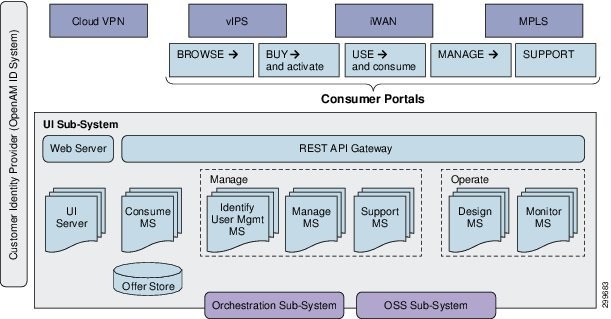
Service Interface
The Customer Facing Service (CFS) role is VMS Solution customer experience, it is the responsibility of the Service Interface to capture the service intent of the customer and then form the service request to Cisco Network Service Orchestrator (NSO). The Service Interface is composed of two subsystems, the Front-End and the Back-End. The Front-End is the Web portal that supports several roles, admin, operator, and customer. Based on a Username/Password combination, the Service Interface determines the role of the user based on the log on authentication process. With a successful authentication, the user is directed to the Web based on the pre-defined role of the username. The Back-End is the composition of micro-services that together communicate with various components in the VMS Solution. From the customer perspective, the Back-End is responsible for processing their service intent, based on the interaction with the customer Web interface or self-service user portal, and creating a parameterized service request to send to the VMS Platform NSO.
Service Interface Reference Architecture shows a modular view of the Service Interface, the Front-End consists of several portal interfaces, that based on a user role, provides the following operations:
The VMS Services that are available through the portals are dependent on the Service Packages made available by the Service Provider; currently VMS provides the Cloud VPN and Cloud IWAN service packages. Access to various interface portals is based on the role of the user, determined during the login process; all interface access is secured by a password. The VMS Service Interface utilizes an OpenAM ID system to determine customer identity; the user login information is available to the Front-End and Back-End modules.
The Service Interface Back-End communicates with the Front-End through a REST API Gateway. The interface portals of the Front-End rely on Back-End micro-services to process user data entered in the various interface portal screens. Dependent on the type of interface portal and data entered, the information will be sent to/from the Back-End API and delivered to/sent from the micro-service responsible for processing the incoming data. The Back-End micro-services are responsible for multiple functions listed below; individual micro-services communicates with VMS modules or other OSS modules to fulfill their functions.
■![]() Business functions microservices
Business functions microservices
–![]() Identity Management provides authentication and authorization. (Authorization is the component that defines what you have access to. Federation with other identity engines is possible, but requires integration.)
Identity Management provides authentication and authorization. (Authorization is the component that defines what you have access to. Federation with other identity engines is possible, but requires integration.)
–![]() Manage (Service Provisioning and Life-Cycle)
Manage (Service Provisioning and Life-Cycle)
–![]() Monitor (Service Status and Metrics)
Monitor (Service Status and Metrics)
–![]() Orchestration (NSO RFS Integrations)
Orchestration (NSO RFS Integrations)
–![]() Notification (Email Templates)
Notification (Email Templates)
–![]() Scalable, swappable and extensible (DevOps Enablement)
Scalable, swappable and extensible (DevOps Enablement)
–![]() Each service can be deployed independently of other services - easier to deploy new versions of services frequently
Each service can be deployed independently of other services - easier to deploy new versions of services frequently
–![]() Each microservice is relatively small (Easier for a developer to understand)
Each microservice is relatively small (Easier for a developer to understand)
–![]() Improved fault isolation. For example, if there is a memory leak in one service then only that service will be affected
Improved fault isolation. For example, if there is a memory leak in one service then only that service will be affected
–![]() Each service can be developed and deployed independently
Each service can be developed and deployed independently
–![]() Eliminates any long-term commitment to a technology stack
Eliminates any long-term commitment to a technology stack
■![]() Robust and well documented REST APIs to enable custom app development
Robust and well documented REST APIs to enable custom app development
–![]() Use our out-of-box UI or build your own
Use our out-of-box UI or build your own
■![]() Supports heterogeneous identity providers (IDM)
Supports heterogeneous identity providers (IDM)
Figure 7 Service Interface Reference Architecture
The Service Interface and serves as the Customer Facing Service layer in the architecture. Designed as two separate modules, the Service Interface’s Front-End and Back-End both play important roles in simplifying the provisioning of services.
As part of solution simplification, the Front-End is designed as an all in one Web based solution GUI. Based on the user login type, the user will be presented with one of three service interfaces: administer, operator, or user. The Service Interface, based on user role, will allow the Service Provider administrator to provision tenant space for end-users, while the Service Provider operator can view the status of all services running, and lastly the user role is for the Service Provider end-customer to order the service based on their requirements.
The Service Interface also contains an independent Back-End module that is responsible for forming a user service definition or intent into a well-defined request to present to the VMS Platform for service provisioning. The Back-End is designed with a REST interface, allowing the Service Provider the choice of Front-Ends, the VMS Service Interface or another OSS front-end. The logic behind the inclusion of a Service Interface Back-End is to ensure a well-formed service request message to the VMS Solution.
Architecture and ETSI Mano Standards
The ETSI NFV Management and Orchestration (MANO) standards define a method of orchestration whereby the components of orchestration of compartmentalized to specific functions. VMS Uses ETSI Mano Architecture for Orchestration shows the ETSI MANO model. The layers are broken into Orchestrator (NFVO), Life Cycle Management (VNF-M), and virtual interface management (VIM). The NFV orchestrator is responsible for understanding the overall service being instantiated. The life cycle management is for the management and monitoring of virtual network functions (VNFs). Finally, the VIM handles interconnecting physically and virtual network and compute infrastructure.
Figure 8 VMS Uses ETSI Mano Architecture for Orchestration

Cisco Virtual Managed Services solution follows the ETS MANO model as show in VMS Orchestration Component Mapping. The Cisco Network Services Orchestrator (NSO) orchestration engine software modules handle the NFVO functions. The Elastic Services Controller (ESC) software modules are responsible for VNF life cycle management (VNF-M). OpenStack networking software plug-ins modules provide virtual infrastructure management (VIM) functionality.
Figure 9 VMS Orchestration Component Mapping

Cisco Network Services Orchestrator (NSO)
Cisco NSO provides the automated services orchestration capabilities. Cisco NSO receives a service intent request through the open API interface presented northbound to the service interface (or customer OSS/BSS). For all services intended to be instantiated, NSO has a Yang service definition model loaded into the transaction database to handle such a request. These are shown in VMS VNF-Orchestrator—NSO as individual service intent modules.
Figure 10 VMS VNF-Orchestrator—NSO
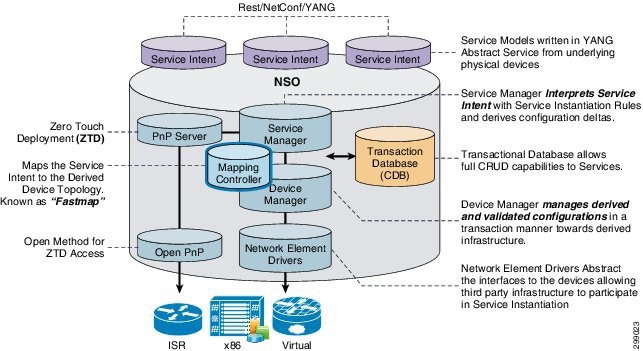
The Service Manager software subcomponent of NSO processes the service intent, corresponding to a particular service model. The purpose of the Service Manager is to analyze the service request, then interpret the request to a specific set of configuration asks. Similarly, the Device Manager is used to abstract out the infrastructure also based on a modeling language. A Mapping Controller is responsible for moving service models to device models. This will be discussed in more detail in later sections.
A transaction database known as the “CDB” stores all elements related to configuration and devices. This highly functional database can be used to derive all the transaction necessary to push a service intent to service instantiation.
Network Element Driver (NED) software modules are used to abstract out the different physical and network devices to which service configuration data may be pushed. As such the NED allows the service definition models to apply to equipment from different vendors.
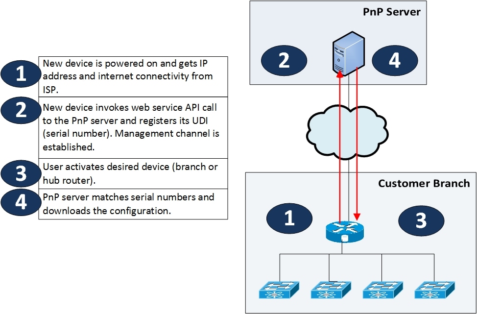
Cisco NSO as the Plug-and-Play Server
The Plug-and-Play (PnP) Server software element is used to handle and achieve zero touch deployment (ZTD) for CPEs coming online and wanting to utilize the services configured orchestration engine. In the VMS solution, NSO also functions as the PnP server. The site CPE deployments are supported in VMS by a PnP service, which is accessible as a NSO PnP Resource Facing Service (RFS) API. Once a CPE device is connected to the Internet, a “call home” protocol communicates with the NSO PnP RFS API via a secure PnP Configuration Manager located in the Service Provider VMS Cloud. The CPE device is fully configure using a four step process:
■![]() Day-(-1) —Initial config of CPE to find PnP Server
Day-(-1) —Initial config of CPE to find PnP Server
■![]() Day-0 —Configuration of the device management interface
Day-0 —Configuration of the device management interface
■![]() Day-1 —System configuration, basic interface and system configuration
Day-1 —System configuration, basic interface and system configuration
■![]() Day-2 —Service configuration, service specific configuration
Day-2 —Service configuration, service specific configuration
Inclusion of the PnP service in the VMS Solution removes costly truck-rolls from the service deployment model, which are required to install and configure each CPE device. The removal of this activity greatly reduces the cost of service deployment, a cost that has long haunted traditional Managed Services.
The illustration below depicts the device registration process.
Figure 11 Registering a Device or CPE
Cisco Elastic Service Controller (ESC)
The elastic services controller software module provides the automation of life cycle management for any VNFs that a service needs to have instantiated—also known as the VNF-M in ETSI MANO terms. There are three main functions achieved through the ESC software module including service provisioning, a rules engine, and service monitoring (see VMS VNF-Manager—ESC).

The service provisioning function takes its VNF instantiation actions from NSO requests which are pushed down via a NED software process into the ESC. The purpose of ESC software module is to bring VNF devices online and be network reachable and configurable from the NSO software modules. The ESC software module use calls to the OpenStack networking software modules to accomplish the tasks of launching virtual machines. Specifically, the ESC software will call the OpenStack Nova software process for compute launch and the OpenStack Neutron software process to establish network connectivity to the newly created virtual machines. The OpenStack VIM software has no knowledge of the overall service being instantiated. OpenStack software is merely acting on the requests pushed by ESC software. All external networks must be created in OpenStack prior to the NSO instantiating the service requests.
The rules engine drives a critical feature of the ESC software, elasticity. Elasticity refers to the ability to spin up additional VNFs that may be required from increasing service load. Conversely elasticity also includes removing VNFs from service when they are no longer needed. In this release, the elasticity configuration is locked at “1” in the ESC software schema. This will prevent the VNFs from scaling up or down. The configurability of the ESC software rules engine elasticity factor will be enabled in subsequent releases.
Service monitoring is essential for detecting whether a VNF has stopped operating or is no longer functioning as expected per the service level agreement (SLA). The ESC software module uses various mechanisms such as SNMP and Ganglia, to detect that a VNF is acting out of profile. When this occurs, the ESC software restarts the VNF, maintaining the user license, and potentially being moved to a new compute resource if necessary. The VNF service monitoring information may also be sent as traps northbound via Open APIs to service assurance tools.
VMS Virtual Infrastructure Manager—OpenStack
The VMS platform assumes the Mitaka version of OpenStack as a Virtual Infrastructure Manager (VIM). The Elastic Service Controller will communicates with OpenStack Nova compute services and Neutron network service to provision Cloud VPN VNF types and create the a network connectivity. OpenStack is implemented as a series of controller services, these services are installed independent of VMS and requires dedicated servers.
For provisioning of VNF, the ESC communicates through a Nova REST Interface to provision a VM based on a particular VNF Type resources and image requirements. Provisioning of the virtual interfaces, Linux Bridges and OVS segments, the ESC communicates through a Neutron REST Interface. Lastly, VNF lifecycle operations utilize the same REST interfaces.
 Feedback