- Overview
- Getting Started
- Configuring RBAC
- Configuring Primary Authentication
- Configuring Trusted Points
- Configuring VM Managers
- Configuring System Profiles
- Configuring Tenants
- Configuring Service Policies and Profiles
- Configuring Device Policies and Profiles
- Configuring Managed Resources
- Integrating with DCNM
- Configuring Administrative Operations
- Service Path Configuration Workflow
- Configuring Service Policies
- Configuring IP Audit and IP Audit Signature Policies
- Configuring NAT/PAT Policies and Policy Sets
Configuring Service Policies and Profiles
This section includes the following topics:
- Service Path Configuration Workflow
- Configuring Service Policies
- Working with Profiles
- Configuring Security Profiles
- Configuring Security Policy Attributes
Service Path Configuration Workflow
Service paths enable you to apply multiple services to VM traffic by binding a sequence of services to a specific port profile.
The following table identifies the tasks required to configure a service path, related topics, and the minimum role required for each task:
| Task | Related Topic | Role Required | ||
|---|---|---|---|---|
|
1. Confirm that the prerequisites are met. |
admin |
|||
|
2. Create the tenant and, if needed, the subordinate organization in which the service path will reside. |
See Creating a Tenant. |
admin |
||
|
3. Add a port profile to a Nexus 1000V VSM.
|
admin |
|||
|
4. Create service nodes for inclusion in the service path. |
tenant-admin |
|||
|
5. Create a service path with service entries. |
tenant-admin |
|||
|
6. Bind the service path to the VSM port profile. |
tenant-admin |
- Prerequisites for Configuring Service Paths
- Adding a Port Profile to a VSM
- Creating a Service Node
- Creating a Service Path
- Binding a Service Path to a Port Profile
Prerequisites for Configuring Service Paths
The following table describes the prerequisites for configuring service paths:
Adding a Port Profile to a VSM
enables you to add a port profile to an enterprise VSM. You cannot add a port profile to a cloud VSM.
If an enterprise VSM has preconfigured port profiles or virtual service configurations that were created outside of , these configurations will not be displayed in the GUI.
If you create a port profile in and specify a VLAN, you must create the VLAN itself on the VSM and then add it to the necessary system and uplink port profiles. The same steps apply for VLANs that you specify while creating service devices, such as edge or compute firewalls: you must create the VLANs on the devices, and then add them to the appropriate system and uplink port profiles.
Confirm the following:
1. Choose Resource Management > Resources > VSMs > vsm, then click Edit.
2. Above the Port Profile table, click Add.
3. In the Add Port Profile dialog box, enter the required information as follows, then click OK:
DETAILED STEPS
The NICs table is populated automatically after you bind a service path to the port profile and the service path is used the first time. For more information about configuring a service path and binding it to a port profile, see Service Path Configuration Workflow.
Creating a Service Node
A service node identifies a virtual service device that can be used in a service path and provides basic configuration for that device.
If either of these situations occurs, an error message will be generated when you attempt to bind the service path to the VSM port profile.
1. Choose Policy Management > Service Policies > root > tenant > Policy Helpers > Service Node, and then click Add Service Node.
2. In the Add Service Node dialog box, provide the following information, and then click OK:
DETAILED STEPS
Creating a Service Path
After you create service nodes, you can create a service path that uses the nodes. Traffic using the service path moves from one service node to another in the sequence that you specify.
 Note | You cannot use a service node more than once in a service path. |
Confirm that you have Tenant Management privileges.
1. Choose Policy Management > Service Policies > root > tenant > Policies > Service Path, and then click Add Service Path.
2. In the Add Service Path dialog box, enter a name and description for the service path, and then click Add Service Entry.
3. In the Add Service Entry dialog box, provide the following information, and then click OK:
4. Add additional service entries as needed for the service path and click OK.
DETAILED STEPS
What to Do Next
You must bind the service path to a port profile so that the service path can be created on the Nexus 1000V VSM. After the service path is bound to a port profile, the traffic using that port profile follows the service entries in the sequence indicated in the table.
Binding a Service Path to a Port Profile
Binding a service path to a port profile ensures that all traffic using that port profile will follow the configured service path. When you bind a service path to a port profile, the NICs table that is displayed in the Edit Port Profile dialog box remains empty until the service path is used for the first time. When the service path is used, the NICs table is populated automatically.
Confirm the following:
Configuring Service Policies
This procedure describes the general steps for configuring service policies for managed resources.
1. Choose Policy Management > Service Policies > root > Policies > policy-type.
2. In the General tab, click Add policy-type.
3. In the dialog boxes that follow, enter the required information. For more information on each dialog box, click the online-help.
DETAILED STEPS
Configuring ACL Policies and Policy Sets
The following topics describe how to configure ACL policies and policy sets:
Adding an ACL Policy
1. Choose Policy Management > Service Policies > root > Policies > ACL > ACL Policies.
2. In the General tab, click Add ACL Policy.
3. In the Add ACL Policy dialog box, enter a name and brief description for the policy, then click Add Rule.
4. In the Add Rule dialog box, specify the required information as described in Add ACL Policy Rule Dialog Box, then click OK.
DETAILED STEPS
| Step 1 | Choose Policy Management > Service Policies > root > Policies > ACL > ACL Policies. | ||
| Step 2 | In the General tab, click Add ACL Policy. | ||
| Step 3 | In the Add ACL Policy dialog box, enter a name and brief description for the policy, then click Add Rule. | ||
| Step 4 | In the Add Rule dialog box, specify the required information as described in Add ACL Policy Rule Dialog Box, then click OK.
The Add Rule dialog box contains settings for time rules for ACL policies. For more information about using time ranges with ACL policies, see Time Ranges in ACL Policy Rules. |
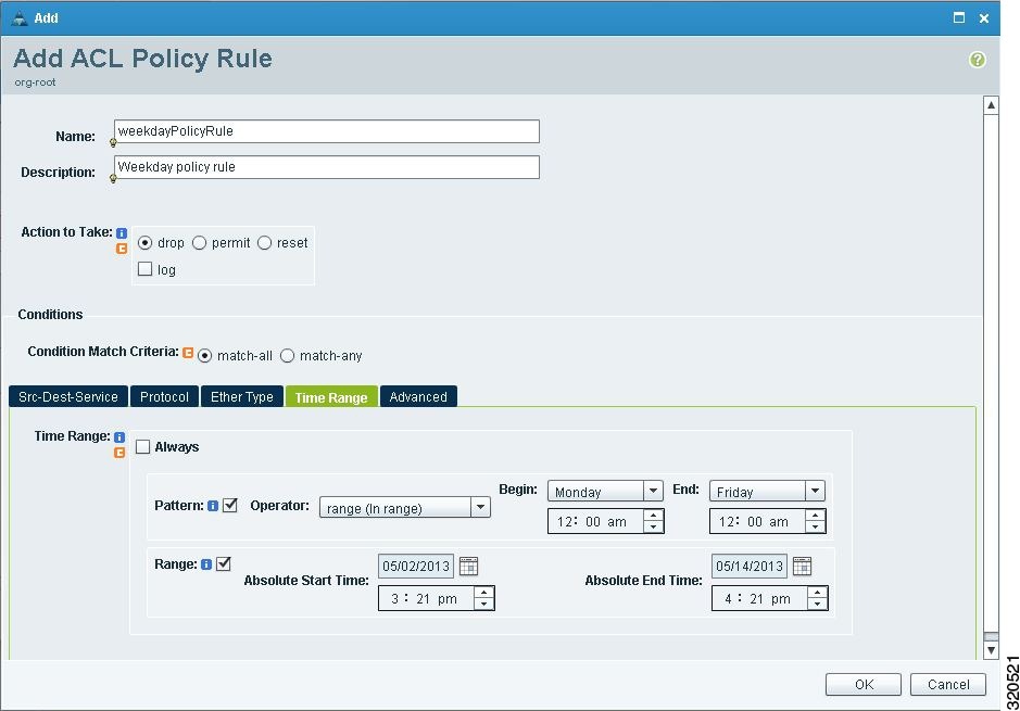
Add ACL Policy Rule Dialog Box
Time Ranges in ACL Policy Rules
Periodic—Specified by day-of-week start and end times (such as Sunday to Sunday), or a frequency (such as Daily, Weekdays, or Weekends). Periodic range start and end times also include options for hours and minutes.
Absolute—Specified by a calendar date and time for start and end times, such as 01 Sep 2013 12:00 AM to 31 Dec 2013 12:00 AM.
The following figure shows the Time Range fields for an ACL policy rule.
Adding an ACL Policy Set
1. Choose Policy Management > Service Policies > root > Policies > ACL > ACL Policy Sets.
2. In the General tab, click Add ACL Policy Set.
3. In the Add ACL Policy Set dialog box, enter the required information as described in the following table, then click OK:
DETAILED STEPS
| Step 1 | Choose Policy Management > Service Policies > root > Policies > ACL > ACL Policy Sets. | ||||||||||||||||||
| Step 2 | In the General tab, click Add ACL Policy Set. | ||||||||||||||||||
| Step 3 | In the Add ACL Policy Set dialog box, enter the required information as described in the following table, then click OK:
| ||||||||||||||||||
Configuring Connection Timeout Policies
enables you to configure connection timeout policies so that you can establish timeout limits for different traffic types.
After you create a connection timeout policy, you can associate it with an edge security profile. For more information, see Configuring Edge Security Profiles.
1. Choose Policy Management > Service Policies > root > Policies > Connection Timeout.
2. In the General tab, click Add Connection Timeout Policy.
3. In the Add Connection Timeout Policy dialog box:
4. To add a rule to the policy, click Add Rule.
5. In the Add Connection Timeout Policy Rule dialog box, provide the information as described in Add Connection Timeout Policy Rule Dialog Box.
DETAILED STEPS
| Step 1 | Choose Policy Management > Service Policies > root > Policies > Connection Timeout. |
| Step 2 | In the General tab, click Add Connection Timeout Policy. |
| Step 3 | In the Add Connection Timeout Policy dialog box: |
| Step 4 | To add a rule to the policy, click Add Rule. |
| Step 5 | In the Add Connection Timeout Policy Rule dialog box, provide the information as described in Add Connection Timeout Policy Rule Dialog Box. |
Add Connection Timeout Policy Rule Dialog Box
| Field | Description |
|---|---|
|
Name |
Policy name. |
|
Description |
Brief policy description. |
|
Action |
|
|
Idle TCP |
Length of time (in days, hours, minutes, and seconds) a TCP connection can remain idle before it is closed. |
|
Half-Closed |
Length of time (in days, hours, minutes, and seconds) a half-closed TCP connection can remain idle before it is freed. |
|
Send Reset To Idle Connection |
Check the check box to send a reset to the TCP endpoints when a TCP connection times out. |
|
Idle UDP |
Length of time (in days, hours, minutes, and seconds) a UDP connection can remain idle before it closes. The duration must be at least one minute, and the default value is two minutes. Enter 00:00:00:00 to disable timeout. |
|
ICMP |
Length of time (in days, hours, minutes, and seconds) an ICMP state can remain idle before it is closed. |
|
Protocol |
Not available for configuration. |
|
Source Conditions |
|
|
Destination Conditions |
|
Configuring DHCP Policies
You can also configure DHCP relay servers for inclusion in DHCP relay policies.
The DHCP relay and DHCP server policies can be authored at the organization level and can be applied only to the inside interface of an edge firewall. When they are applied, DHCP policies allow the edge firewall to act either as a DHCP server or a DHCP relay for all VMs in the inside network.
You can apply only one DHCP server or relay profile at a time to the inside interface of the edge firewall.
For more information, see the following topics:
Adding a DHCP Relay Server
DHCP relay servers are used to forward DHCP requests and replies between clients and servers when they are not on the same physical subnet. In contrast to IP router forwarding, where IP datagrams are switched between networks, DHCP relay servers receive DHCP messages and then generate a new message to send out on a different interface.
1. Choose Policy Management > Service Policies > root > Policies > DHCP > DHCP Relay Server.
2. In the General tab, click Add DHCP Relay Server.
3. In the New DHCP Relay Server dialog box, provide the information described in the Add DHCP Relay Server Dialog Box, then click OK.
DETAILED STEPS
| Step 1 | Choose Policy Management > Service Policies > root > Policies > DHCP > DHCP Relay Server. |
| Step 2 | In the General tab, click Add DHCP Relay Server. |
| Step 3 | In the New DHCP Relay Server dialog box, provide the information described in the Add DHCP Relay Server Dialog Box, then click OK. |
Add DHCP Relay Server Dialog Box
| Field | Description |
|---|---|
Name |
Relay server name. |
Description |
Brief description of the relay server. |
Relay Server IP |
IP address of the relay server. |
Interface Name |
Interface to use to reach the relay server. |
Configuring a DHCP Relay Policy
enables you to associate a DHCP relay server with a DHCP relay policy, as described in this procedure.
1. Choose Policy Management > Service Policies > root > Policies > DHCP > DHCP Relay.
2. In the General tab, click Add DHCP Relay Policy.
3. In the New DHCP Relay Policy dialog box, provide the information described in Add DHCP Relay Policy Dialog Box, then click OK.
DETAILED STEPS
| Step 1 | Choose Policy Management > Service Policies > root > Policies > DHCP > DHCP Relay. |
| Step 2 | In the General tab, click Add DHCP Relay Policy. |
| Step 3 | In the New DHCP Relay Policy dialog box, provide the information described in Add DHCP Relay Policy Dialog Box, then click OK. |
Add DHCP Relay Policy Dialog Box
| Name | Description |
|---|---|
|
Name |
Policy name. |
|
Description |
Brief policy description. |
|
DHCP Relay Server Assignment |
Assign a DHCP relay server in one of the following ways:
You must assign at least one DHCP relay server to the policy. |
Configuring a DHCP Server Policy
A DHCP server policy enables you to define the characteristics of the policy, such as ping and lease timeouts, IP address range, and DNS and WINS settings.
1. Choose Policy Management > Service Policies > root > Policies > DHCP > DHCP Server.
2. In the General tab, click Add DHCP Server Policy.
3. In the New DHCP Server Policy dialog box, provide the information as described in Add DHCP Server Policy Dialog Box, then click OK.
DETAILED STEPS
| Step 1 | Choose Policy Management > Service Policies > root > Policies > DHCP > DHCP Server. |
| Step 2 | In the General tab, click Add DHCP Server Policy. |
| Step 3 | In the New DHCP Server Policy dialog box, provide the information as described in Add DHCP Server Policy Dialog Box, then click OK. |
Add DHCP Server Policy Dialog Box
| Field | Description |
|---|---|
| General Tab | |
|
Name |
Policy name. |
|
Description |
Brief policy description. |
|
Ping Timeout (Milliseconds) |
Amount of time (in milliseconds) that the DHCP server waits for a ping reply before it stops attempting to reach a pool address for client assignment. The valid range is 10 to 10000 milliseconds. |
|
Lease Timeout |
Amount of time (in days, hour, minutes, and seconds) that the DHCP server allocates an IP address to a DHCP client before reclaiming and then reallocating it to another client. The default value is 00:01:00:00 (one hour). |
|
Edge Device Interface Using the DHCP Client for DHCP Server Auto Configuration |
To enable DHCP server automatic configuration, enter the name of the edge device interface that uses the DHCP client. For ASA 1000V instances, this interface is always an outside interface. Leaving this field empty indicates that the automatic configuration feature is disabled. |
|
DNS Settings |
DNS settings used by the edge firewall when configuring DHCP clients. To add a new entry, click Add DNS Setting and add the required information. |
|
WINS Servers |
Windows Internet Naming Service (WINS) name servers that are available to DHCP clients. To add a new WINS server, click Add WINS Server and enter the WINS server IP address. WINS servers are listed in the order of preference, with the most preferred WINS server at the top. Select an entry in the table, and then use the arrows above the table to change server priority. |
|
IP Address Range |
Enter the following information for the DHCP address pool:
|
The Advance tab allows you to add Manual and Exclude addresses. You must know the applicable MAC and IP addresses.
Configuring IP Audit and IP Audit Signature Policies
The IP audit feature provides basic Intrusion Prevention System (IPS) support for ASA 1000V instances. supports a basic list of signatures, and enables you to configure policies that specify one or more actions to apply to traffic that matches a signature.
When you associate an IP audit policy with a device, the policy is applied to all traffic on the outside interface of the device.
The following topics describe how to configure these policies.
Configuring IP Audit Policies
1. Choose Policy Management > Service Policies > root > Policies > IP Audit > Audit Policies.
2. In the General tab, click Add IP Audit Policy.
3.
In the Add IP Audit Policy dialog box provide the following information:
4. To add a rule to the policy, click Add Rule in the Rule Table toolbar.
5. In the Add IP Audit Policy Rule dialog box, provide the information as described in Add IP Audit Policy Rule Dialog Box, then click OK in the open dialog boxes.
DETAILED STEPS
| Step 1 | Choose Policy Management > Service Policies > root > Policies > IP Audit > Audit Policies. |
| Step 2 | In the General tab, click Add IP Audit Policy. |
| Step 3 | In the Add IP Audit Policy dialog box provide the following information: |
| Step 4 | To add a rule to the policy, click Add Rule in the Rule Table toolbar. |
| Step 5 | In the Add IP Audit Policy Rule dialog box, provide the information as described in Add IP Audit Policy Rule Dialog Box, then click OK in the open dialog boxes. |
Add IP Audit Policy Rule Dialog Box
| Field | Description |
|---|---|
|
Name |
Rule name. |
|
Description |
Brief rule description. |
|
Attack-Class Action |
Check the check boxes of the actions to take for signature type Attack if the conditions of the rule are met: |
|
Informational-Class Action |
Check the check boxes of the actions to take for signature type Informational if the conditions of the rule are met: |
|
Protocol |
Not available for configuration. |
|
Source Conditions |
|
|
Destination Conditions |
Configuring IP Audit Signature Policies
An IP audit signature policy identifies the signatures that are enabled and disabled. By default, all signatures are enabled. You can disable a signature when legitimate traffic matches the signature in most situations, resulting in false alarms. However, disabling the signature is performed at a global level, meaning that no traffic will trigger the signature (even bad traffic) when it is disabled.
1. Choose Policy Management > Service Policies > root > Policies > IP Audit > Signature Policies.
2. In the General tab, click Add IP Audit Signature Policy.
3. In the Add IP Audit Signature Policy dialog box, enter a name and description for the policy.
4. In the Signatures area, move signatures between the Enabled Signatures and Disabled Signatures lists as required.
5. After you have made all adjustments, click OK.
DETAILED STEPS
| Step 1 | Choose Policy Management > Service Policies > root > Policies > IP Audit > Signature Policies. | ||
| Step 2 | In the General tab, click Add IP Audit Signature Policy. | ||
| Step 3 | In the Add IP Audit Signature Policy dialog box, enter a name and description for the policy. | ||
| Step 4 |
In the Signatures area, move signatures between the Enabled Signatures and Disabled Signatures lists as required.
You can view additional information about a signature by selecting the required signature and clicking Properties. | ||
| Step 5 | After you have made all adjustments, click OK. |
Configuring NAT/PAT Policies and Policy Sets
supports Network Address Translation (NAT) and Port Address Translation (PAT) policies for controlling address translation in the deployed network. These policies support both static and dynamic translation of IP addresses and ports.
-
NAT policy—Can contain multiple rules, which are evaluated sequentially until a match is found.
Note
Edge routers support a limited set of NAT policy options. -
NAT policy set—Group of NAT policies that can be associated with an edge security profile. When the profile is applied, the NAT policies are applied only to ingress traffic.
-
PAT policy—Supports source dynamic and destination static interface PAT on edge firewalls.
The following topics describe how to configure NAT and PAT policies, and NAT policy sets.
- Configuring NAT/PAT Policies
- Configuring NAT Policy Sets
- Configuring PAT for Edge Firewalls
- Configuring Packet Inspection Policies
Configuring NAT/PAT Policies
This procedure describes how to configure NAT/PAT policies with .
1. Choose Policy Management > Service Policies > root > Policies > NAT > NAT Policies.
2. In the General tab, click Add NAT Policy.
3. In the Add NAT Policy dialog box, enter a name and description for the policy.
4. In the Admin State field, indicate whether the administrative state of the policy is to be enabled or disabled.
5. To add a rule to the policy, click Add Rule.
6. In the Add NAT Policy Rule dialog box, provide the information as described in Add NAT Policy Rule Dialog Box, then click OK in the open dialog boxes.
DETAILED STEPS
| Step 1 | Choose Policy Management > Service Policies > root > Policies > NAT > NAT Policies. |
| Step 2 | In the General tab, click Add NAT Policy. |
| Step 3 | In the Add NAT Policy dialog box, enter a name and description for the policy. |
| Step 4 | In the Admin State field, indicate whether the administrative state of the policy is to be enabled or disabled. |
| Step 5 | To add a rule to the policy, click Add Rule. |
| Step 6 | In the Add NAT Policy Rule dialog box, provide the information as described in Add NAT Policy Rule Dialog Box, then click OK in the open dialog boxes. |
Add NAT Policy Rule Dialog Box
Add NAT Policy Rule Dialog Box
| Field | Description |
|---|---|
|
Name |
Rule name. |
|
Description |
Brief rule description. |
|
Original Packet Match Conditions |
|
|
Source Match Conditions |
Source attributes that must be matched for the current policy to apply. To add a new condition, click Add Rule Condition. Available source attributes are IP Address and Network Port. |
|
Destination Match Conditions |
Destination attributes that must be matched for the current policy to apply. To add a new condition, click Add Rule Condition. Available destination attributes are IP Address and Network Port. |
|
Protocol |
Specify the protocols to which the rule applies: |
|
NAT Action Table |
|
|
NAT Action |
From the drop-down list, choose the required translation option: Static or Dynamic. |
|
Translated Address |
Identify a translated address pool for each original packet match condition from the following options: For example, if you specify a source IP address match condition, you must identify a Source IP Pool object group. Similarly, a destination network port match requires a Destination Port Pool object group. The Source IP PAT Pool option is available only if you choose dynamic translation. Click Add Object Group to add object groups for the translation actions. |
|
NAT Options |
Check and uncheck the check boxes as required:
|
Note | Edge routers support a limited set of NAT policy options. |
Configuring NAT Policy Sets
Policy sets enable you to group multiple policies of the same type (such as NAT, ACL, or Interface) for inclusion in a profile. NAT policy sets are groups of NAT policies that can be associated with an edge security profile.
1. Choose Policy Management > Service Policies > root > Policies > NAT > NAT Policy Sets.
2. In the General tab, click Add NAT Policy Set.
3. In the Add NAT Policy Set dialog box, enter a name and description for the policy set.
4. In the Admin State field, indicate whether the administrative status of the policy is to be enabled or disabled.
5. In the Policies area, select the policies to include in this policy set:
6. Click OK.
DETAILED STEPS
| Step 1 | Choose Policy Management > Service Policies > root > Policies > NAT > NAT Policy Sets. |
| Step 2 | In the General tab, click Add NAT Policy Set. |
| Step 3 | In the Add NAT Policy Set dialog box, enter a name and description for the policy set. |
| Step 4 | In the Admin State field, indicate whether the administrative status of the policy is to be enabled or disabled. |
| Step 5 |
In the Policies area, select the policies to include in this policy set: |
| Step 6 | Click OK. |
Configuring PAT for Edge Firewalls
enables you to configure source and destination interface PAT for edge firewalls, such as the ASA 1000V. For more information, see the following topics.
Configuring Source Dynamic Interface PAT
enables you to configure source dynamic interface PAT for edge firewalls, such as ASA 1000Vs.
1. Choose Policy Management > Service Policies > root > Policies > NAT > NAT Policies.
2. In the General tab, click Add NAT Policy.
3. In the Add NAT Policy dialog box, enter a name and description for the policy.
4. In the Admin State field, indicate whether the administrative state of the policy is to be enabled or disabled.
5. Click Add Rule to add a rule to this policy.
6. In the Add NAT Policy Rule dialog box, provide the information described in Add NAT Policy Rule Dialog Box with the following specific settings, then click OK:
7. Click OK.
DETAILED STEPS
| Step 1 | Choose Policy Management > Service Policies > root > Policies > NAT > NAT Policies. |
| Step 2 | In the General tab, click Add NAT Policy. |
| Step 3 | In the Add NAT Policy dialog box, enter a name and description for the policy. |
| Step 4 | In the Admin State field, indicate whether the administrative state of the policy is to be enabled or disabled. |
| Step 5 | Click Add Rule to add a rule to this policy. |
| Step 6 | In the Add NAT Policy Rule dialog box, provide the information described in Add NAT Policy Rule Dialog Box with the following specific settings, then click OK: |
| Step 7 | Click OK. |
Configuring Destination Static Interface PAT
1. Choose Policy Management > Service Policies > root > Policies > NAT > NAT Policies.
2. In the General tab, click Add NAT Policy.
3. In the Add NAT Policy dialog box, enter a name and description for the policy.
4. In the Admin State field, indicate whether the administrative state of the policy is to be enabled or disabled.
5. Click Add Rule to add a rule to this policy.
6. In the Add NAT Policy Rule dialog box, enter the IP address of the ASA 1000V outside interface as a rule condition for Destination Match Conditions.
7. Configure other options in the Add NAT Policy Rule dialog box as described in Add NAT Policy Rule Dialog Box, then click OK.
8. Click OK.
DETAILED STEPS
| Step 1 | Choose Policy Management > Service Policies > root > Policies > NAT > NAT Policies. | ||
| Step 2 | In the General tab, click Add NAT Policy. | ||
| Step 3 | In the Add NAT Policy dialog box, enter a name and description for the policy. | ||
| Step 4 | In the Admin State field, indicate whether the administrative state of the policy is to be enabled or disabled. | ||
| Step 5 | Click Add Rule to add a rule to this policy. | ||
| Step 6 | In the Add NAT Policy Rule dialog box, enter the IP address of the ASA 1000V outside interface as a rule condition for Destination Match Conditions. | ||
| Step 7 |
Configure other options in the Add NAT Policy Rule dialog box as described in Add NAT Policy Rule Dialog Box, then click OK.
| ||
| Step 8 | Click OK. |
Configuring Packet Inspection Policies
enables you to configure policies for application-layer protocol inspection. Inspection is required for services that embed IP addressing information in the user data packet, or that open secondary channels on dynamically assigned ports. When inspection is configured, the end device performs a deep packet inspection instead of quickly passing the packet on. As a result, inspection can affect overall device throughput.
Protocols Supported for Packet Inspection Policies lists the application-layer protocols supported by .
1. Choose Policy Management > Service Policies > root > Policies > Packet Inspection.
2. In the General tab, click Add Packet Inspection Policy.
3. In the Add Packet Inspection Policy dialog box, enter a name and description for the policy.
4. In the Admin State field, indicate whether the administrative status of the policy is enabled or disabled.
5. To add a rule to the policy, click Add Rule.
6. In the Add Packet Inspection Policy Rule Dialog box, provide the information as described in Add Packet Inspection Policy Rule Dialog Box, then click OK in the open dialog boxes.
DETAILED STEPS
| Step 1 | Choose Policy Management > Service Policies > root > Policies > Packet Inspection. |
| Step 2 | In the General tab, click Add Packet Inspection Policy. |
| Step 3 | In the Add Packet Inspection Policy dialog box, enter a name and description for the policy. |
| Step 4 | In the Admin State field, indicate whether the administrative status of the policy is enabled or disabled. |
| Step 5 | To add a rule to the policy, click Add Rule. |
| Step 6 | In the Add Packet Inspection Policy Rule Dialog box, provide the information as described in Add Packet Inspection Policy Rule Dialog Box, then click OK in the open dialog boxes. |
Protocols Supported for Packet Inspection Policies
|
CTIQBE |
ICMP |
PPTP |
SQL *Net |
|
DCE/RPC |
ICMP Error |
RSH |
SunRPC |
|
DNS |
ILS |
RSTP |
TFTP |
|
FTP |
IP Options |
SIP |
WAAS |
|
H323 H225 |
IPsec Pass-Through |
Skinny |
XDMCP |
|
H323 RAS |
MGCP |
SMTP |
|
|
HTTP |
NetBIOS |
SNMP |
Add Packet Inspection Policy Rule Dialog Box
| Field | Description |
|---|---|
|
Name |
Rule name. |
|
Description |
Brief rule description. |
|
Action |
Under Enable Inspections, check the check boxes of protocols to be inspected if the rule conditions are met. |
|
Protocol |
Not available for configuration. |
|
Source Conditions |
|
|
Destination Conditions |
Configuring Routing Policies
enables you to use routing policies to configure static, OSPF, and BGP routes for managed resources.
Note | You can configure only inside and outside interfaces on edge firewalls by using . Use the CLI to configure routes on the edge firewall management interface. |
After you configure a static route routing policy, you can implement the policy by:
1. Choose Policy Management > Service Policies > root > Policies > Routing.
2. In the General tab, click Add Routing Policy.
3. In the Add Routing Policy dialog box, enter a name and brief description for the routing policy.
4. To add a new static route, click Add Static Route.
5. In the Add Static Route dialog box, enter the following information:
6. Click OK.
DETAILED STEPS
| Step 1 | Choose Policy Management > Service Policies > root > Policies > Routing. |
| Step 2 | In the General tab, click Add Routing Policy. |
| Step 3 | In the Add Routing Policy dialog box, enter a name and brief description for the routing policy. |
| Step 4 | To add a new static route, click Add Static Route. |
| Step 5 | In the Add
Static Route dialog box, enter the following information:
|
| Step 6 | Click OK. |
Configuring TCP Intercept Policies
enables you to configure TCP intercept policies that you can then associate with an edge security profile. TCP intercept policies that you associate with a device via an edge security profile are applied to all traffic on the outside interface of the device.
1. Choose Policy Management > Service Policies > root > Policies > TCP Intercept.
2. In the General tab, click Add TCP Intercept Policy.
3. In the Add TCP Intercept Policy dialog box, enter a name and brief description for the policy.
4. In the Admin State field, indicate whether the administrative status of the policy is to be enabled or disabled.
5. To add a rule to the policy, click Add Rule.
6. In the Add TCP Intercept Policy Rule dialog box, provide the information as described in Add TCP Intercept Policy Rule Dialog Box.
DETAILED STEPS
| Step 1 | Choose Policy Management > Service Policies > root > Policies > TCP Intercept. |
| Step 2 | In the General tab, click Add TCP Intercept Policy. |
| Step 3 | In the Add TCP Intercept Policy dialog box, enter a name and brief description for the policy. |
| Step 4 | In the Admin State field, indicate whether the administrative status of the policy is to be enabled or disabled. |
| Step 5 | To add a rule to the policy, click Add Rule. |
| Step 6 | In the Add TCP Intercept Policy Rule dialog box, provide the information as described in Add TCP Intercept Policy Rule Dialog Box. |
Add TCP Intercept Policy Rule Dialog Box
| Field | Description |
|---|---|
|
Name |
Rule name. |
|
Description |
Brief rule description. |
|
Maximum Number of Embryonic TCP Connections (0-65535) |
Number of embryonic TCP connections allowed overall and per client:
The default value 0 (zero) indicates unlimited connections. |
|
Protocol |
Not available for configuration. |
|
Source Conditions |
Not available for configuration. |
|
Destination Conditions |
Not available for configuration. |
Configuring Site-to-Site IPsec VPN Policies
enables you to configure site-to-site IPsec VPNs. In addition, you can configure a crypto map policy and attach it to an edge profile. For ease of configuration and to keep logical IPsec entities separate, configuration is divided into the following sections:
-
Configuring Crypto Map Policies
-
Configuring IKE Policies
-
Configuring Interface Policy Sets
-
Configuring IPsec Policies
-
Configuring Peer Authentication Policies
-
Configuring VPN Device Policies
To access VPN policies, choose Policy Management > Service Policies > root > Policies > VPN.
- Configuring Crypto Map Policies
- Configuring IKE Policies
- Configuring Interface Policy Sets
- Configuring IPsec Policies
- Configuring Peer Authentication Policies
- Configuring VPN Device Policies
Configuring Crypto Map Policies
Crypto map policies are applied to interfaces by means of their inclusion in interface policy sets and edge security policies.
1. Choose Policy Management > Service Policies > root > Policies > VPN > Crypto Map Policies.
2. In the General tab, click Add Crypto Map Policy.
3. In the Add Crypto Map Policy dialog box, provide the information as described in Add Crypto Map Policy Dialog Box, then click OK.
4. To add a policy rule, click Add Rule in the General tab and provide the required information as described in Add Crypto Map Policy Rule Dialog Box.
DETAILED STEPS
| Step 1 | Choose Policy Management > Service Policies > root > Policies > VPN > Crypto Map Policies. |
| Step 2 | In the General tab, click Add Crypto Map Policy. |
| Step 3 | In the Add Crypto Map Policy dialog box, provide the information as described in Add Crypto Map Policy Dialog Box, then click OK. |
| Step 4 | To add a policy rule, click Add Rule in the General tab and provide the required information as described in Add Crypto Map Policy Rule Dialog Box. |
Add Crypto Map Policy Dialog Box
| Field | Description |
|---|---|
|
General Tab |
|
|
Name |
Policy name. |
|
Description |
Brief policy description. |
|
Admin State |
Whether the administrative status of the policy is enabled or disabled. |
|
Rule Table |
|
|
Add Rule |
Click Add Rule to add a new rule to the current policy. |
|
IPsec Settings Tab |
|
|
SA Lifetime |
Length of time (in days, hours, minutes, and seconds) that a security association (SA) lives before expiring. |
|
SA Lifetime Traffic (KB) |
Volume of traffic, in kilobytes, that can pass between IPsec peers using a given SA before that association expires. |
|
Enable Perfect Forwarding Secrecy |
Whether or not Perfect Forward Secrecy (PFS) is enabled. PFS is a cryptographic characteristic associated with a derived shared secret value. With PFS, if one key is compromised, previous and subsequent keys are not compromised, because subsequent keys are not derived from previous keys. |
|
Diffie-Hellman Group |
Available if PFS is enabled. Choose the Diffie-Hellman (DH) group for this policy: |
|
IPsec Policies |
The IPsec policy that applies to the current policy. Select an existing IPsec policy or click Add IPsec Policy to create a new policy. |
|
Peer Device |
Peer device. Choose an existing peer or click Add Peer Device to add a new peer. In the Add Peer Device dialog box, enter the peer device IP address or hostname. |
|
Other Settings Tab |
|
|
Enable NAT Traversal |
Whether or not IPsec peers can establish a connection through a NAT device. |
|
Enable Reverse Route Injection |
Whether or not static routes are automatically added to the routing table and then announced to neighbors on the private network. |
|
Connection Type |
Connection type for this policy:
|
|
Negotiation Mode |
Mode to use for exchanging key information and setting up SAs: |
|
DH Group for Aggressive Mode |
DH group to use when in aggressive mode: Group 1, Group 2, or Group 5. |
Add Crypto Map Policy Rule Dialog Box
| Field | Description |
|---|---|
|
Name |
Rule name. |
|
Description |
Brief rule description. |
|
VPN Action |
Action to take based on this rule: Permit or Deny. |
|
Protocol |
Protocols to examine for this rule: |
|
Source Conditions |
Source attributes that must be matched for the rule to apply. To add a new condition, click Add Rule Condition. Available source attributes are IP Address and Network Port. |
|
Destination Conditions |
Destination attributes that must be matched for the rule to apply. To add a new condition, click Add Rule Condition. Available destination attributes are IP Address and Network Port. |
Configuring IKE Policies
The Internet Key Exchange (IKE) protocol is a hybrid protocol that implements Oakley and SKEME key exchanges inside the Internet Security Association and Key Management Protocol (ISAKMP) framework. The initial IKE implementation used the IPsec protocol, but IKE can be used with other protocols. IKE provides authentication of the IPsec peers, negotiates IPsec keys, and negotiates the IPsec Security Associations (SAs).
- IKE V1 Policy
Click Add IKE V1 Policy.
In the Add IKE V1 Policy dialog box, provide the information described in IKE V1 Policy Dialog Box, then click OK.
- IKE V2 Policy
Click Add IKE V2 Policy.
In the Add IKE V2 Policy dialog box, provide the information described in IKE V2 Policy Dialog Box, then click OK.
1. Choose Policy Management > Service Policies > root > Policies > VPN > IKE Policies.
2. In the General tab, click Add IKE Policy.
3. In the Add IKE Policy dialog box, enter a name and description for the policy.
4.
Configure either an IKE V1 or IKE V2 policy:
5. Click OK.
DETAILED STEPS
| Step 1 | Choose Policy Management > Service Policies > root > Policies > VPN > IKE Policies. |
| Step 2 | In the General tab, click Add IKE Policy. |
| Step 3 | In the Add IKE Policy dialog box, enter a name and description for the policy. |
| Step 4 | Configure either an IKE V1 or IKE V2 policy:
|
| Step 5 | Click OK. |
IKE V1 Policy Dialog Box
| Field | Description |
|---|---|
|
DH Group |
Diffie-Hellman group: Group 1, Group 2, or Group 5. |
|
Encryption |
Encryption method: 3DES, AES, AES-192, AES-256, or DES. |
|
Hash |
Hash algorithm: MD5 or SHA. |
|
Authentication |
Authentication method is Preshared key. |
|
SA Lifetime |
Length of time (in days, hours, minutes, and seconds) that an SA lives before expiring. |
IKE V2 Policy Dialog Box
| Field | Description |
|---|---|
|
DH Group |
Diffie-Hellman group: Group 1, Group 2, Group 5, or Group 14. |
|
Encryption |
Encryption method: 3DES, AES, AES-192, AES-256, or DES. |
|
Hash |
Hash integrity algorithm: MD5, SHA, SHA256, SHA384, or SHA512. |
|
Pseudo Random Function Hash |
Pseudo-random function (PRF) has algorithm: MD5, SHA, SHA256, SHA384, or SHA512. |
|
SA Lifetime |
Length of time (in days, hours, minutes, and seconds) that an SA lives before expiring. |
Configuring Interface Policy Sets
Interface policy sets enable you to group multiple policies for inclusion in an edge security profile.
1. Choose Policy Management > Service Policies > root > Policies > VPN > Interface Policy Sets.
2. In the General tab, click Add Interface Policy Set.
3. In the Add Interface Policy Set dialog box, provide the information as described in Add Interface Policy Set Dialog Box, then click OK.
DETAILED STEPS
| Step 1 | Choose Policy Management > Service Policies > root > Policies > VPN > Interface Policy Sets. |
| Step 2 | In the General tab, click Add Interface Policy Set. |
| Step 3 | In the Add Interface Policy Set dialog box, provide the information as described in Add Interface Policy Set Dialog Box, then click OK. |
Add Interface Policy Set Dialog Box
General Tab
| Field | Description |
|---|---|
|
Name |
Policy set name. |
|
Description |
Brief description of the policy set. |
|
Admin State |
Administrative state of the policy set: enabled or disabled. |
|
Policies Area |
|
|
Add Crypto Map Policy |
Click to add a new policy. |
|
Available |
Policies that can be assigned to the policy set. Use the arrows between the columns to move policies between columns. |
|
Assigned |
Policies assigned to the policy set. |
|
Up and down arrows |
Changes the priority of the selected policies. Arrange the policies from highest to lowest priority, with the highest priority policy at the top of the list. |
Domain Settings Tab
| Field | Description |
|---|---|
|
Enable IKE (Must check at least one) |
Check the appropriate check box to specify IKE V1 or IKE V2. |
|
Enable IPsec Pre-fragmentation |
Check the check box to fragment packets before encryption. Pre-fragmentation minimizes post-fragmentation (fragmentation after encryption) and the resulting reassembly before decryption, thereby improving performance. |
|
Do Not Fragment |
Available only if the Enable IPsec Pre-fragmentation check box is checked. From the drop-down list, choose the action to take with the Don't Fragment (DF) bit in the encapsulated header: |
Configuring IPsec Policies
IPsec policies define the IPsec policy objects used to create a secure IPsec tunnel for a VPN.
1. Choose Policy Management > Service Policies > root > Policies > VPN > IPsec Policies.
2. In the General tab, click Add IPsec Policy.
3. In the Add IPsec Policy dialog box, enter a name and description for the policy.
4. To configure an IKE V1 proposal:
5. To configure an IKE V2 proposal:
6. Click OK to save the policy.
DETAILED STEPS
| Step 1 | Choose Policy Management > Service Policies > root > Policies > VPN > IPsec Policies. |
| Step 2 | In the General tab, click Add IPsec Policy. |
| Step 3 |
In the Add IPsec Policy dialog box, enter a name and description for the policy. You must configure ethier an IKE V1 or IKE V2 proposal for an IPsec policy. |
| Step 4 | To configure an IKE V1 proposal:
|
| Step 5 | To configure an IKE V2 proposal:
|
| Step 6 | Click OK to save the policy. |
IPsec IKEv1 Proposal Dialog Box
| Field | Description |
|---|---|
|
Mode |
Mode in which the IPsec tunnel operates. In Tunnel mode, the IPsec tunnel encapsulates the entire IP packet. |
|
ESP Encryption |
Encapsulating Security Protocol (ESP) encryption method:
|
|
ESP Authentication |
Hash authentication algorithm: |
IPsec IKEv2 Proposal Dialog Box
| Field | Description |
|---|---|
|
ESP Encryption Algorithm Table |
To add an ESP encryption method:
|
|
Integrity Algorithm Table |
To add an integrity algorithm: |
Configuring Peer Authentication Policies
Use a peer authentication policy to define the method used to authenticate a peer.
1. Choose Policy Management > Service Policies > root > Policies > VPN > Peer Authentication Policies.
2. In the General tab, click Add Peer Authentication Policy.
3. In the Add Peer Authentication Policy dialog box, enter a name and description for the policy.
4. Click Add Policy to Authenticate Peer.
5. In the Add Policy to Authenticate Peer dialog box, provide the information described in Add Policy to Authenticate Peer Dialog Box, then click OK.
6. Click OK to save the policy.
DETAILED STEPS
| Step 1 | Choose Policy Management > Service Policies > root > Policies > VPN > Peer Authentication Policies. |
| Step 2 | In the General tab, click Add Peer Authentication Policy. |
| Step 3 | In the Add Peer Authentication Policy dialog box, enter a name and description for the policy. |
| Step 4 | Click Add Policy to Authenticate Peer. |
| Step 5 | In the Add Policy to Authenticate Peer dialog box, provide the information described in Add Policy to Authenticate Peer Dialog Box, then click OK. |
| Step 6 | Click OK to save the policy. |
Add Policy to Authenticate Peer Dialog Box
| Field | Description |
|---|---|
|
Peer Device (Unique) |
Unique IP address or hostname of the peer. |
|
IKEv1 Area |
|
|
Local |
Preshared key. |
|
Confirm |
Preshared key for confirmation. |
|
Set |
Whether or not the preshared key has been set and is properly configured (read-only). |
|
IKEv2 Area |
|
|
Local |
Local preshared key. |
|
Confirm |
Local preshared key for confirmation. |
|
Set |
Whether or not the local preshared key has been set and is properly configured (read-only). |
|
Remote |
Remote preshared key. |
|
Confirm |
Remote preshared key for confirmation. |
|
Set |
Whether or not the remote preshared key has been set and is properly configured (read-only). |
Configuring VPN Device Policies
1. Choose Policy Management > Service Policies > root > Policies > VPN > VPN Device Policies.
2. In the General tab, click Add VPN Device Policy.
3. In the Add VPN Device Policy dialog box, provide the information as described in Add VPN Device Policy Dialog Box.
4. As needed, provide the information described in the following tables:
5. Click OK to create the policy.
DETAILED STEPS
| Step 1 | Choose Policy Management > Service Policies > root > Policies > VPN > VPN Device Policies. |
| Step 2 | In the General tab, click Add VPN Device Policy. |
| Step 3 | In the Add VPN Device Policy dialog box, provide the information as described in Add VPN Device Policy Dialog Box. |
| Step 4 | As needed, provide the information described in the following tables: |
| Step 5 | Click OK to create the policy. |
Add VPN Device Policy Dialog Box
General Tab
Note | A VPN device policy requires both an IKE policy and a peer authentication policy. |
| Field | Description |
|---|---|
Name |
Policy name. |
Description |
Brief policy description. |
IKE Policy |
Choose an existing policy from the drop-down list, or click Add IKE Policy to add a new policy. |
Peer Authentication Policy |
Choose an existing policy from the drop-down list, or click Add Peer Authentication Policy to add a new policy. |
IKE Settings Tab
| Field | Description |
|---|---|
Enable IPsec over TCP |
Whether or not IPsec traffic is allowed over TCP. If IPsec over TCP is enabled, this method takes precedence over all other connection methods. |
Send Disconnect Notification |
Whether or not clients are notified that sessions will be disconnected. |
Allow Inbound Aggressive Mode |
Whether or not inbound aggressive mode is permitted. |
Wait for Termination before Rebooting |
Whether or not a reboot can occur only when all active sessions have terminated voluntarily. |
Threshold for Cookie Challenge (0-100 Percent) |
Percentage of the maximum number of allowed Security Associations (SAs) that can be in-negotiation (open) before cookie challenges are issued for future SA negotiations. |
Negotiation Threshold for Maximum SAs (0-100 Percent) |
Percentage of the maximum number of allowed SAs that can be in-negotiation before additional connections are denied. The default value is 100 percent. |
IKE Identity |
|
Key for IKE Identity |
The key to use for IKE identify if the IKE identification method is Key ID. |
NAT Traversal |
Whether or not IPsec peers can establish a connection through a NAT device. |
Keep-Alive Time for NAT Traversal |
Length of time (in hours, minutes, and seconds) that a tunnel can exist with no activity before the device sends keepalive messages to the peer. Values range from 10 to 3600 seconds, with a default of 20 seconds. |
IKEv2 IPsec Maximum Security Associations |
Whether or not the total number of IKE V2 SAs on the node can be set. |
Maximum Number of SA |
Maximum number of SA connections allowed. |
IKEv1 over TCP Port Table |
IPsec Settings Tab
| Field | Description |
|---|---|
Anti Replay |
Whether or not SA anti-replay is enabled. |
Anti Replay Window Size |
Window size to use to track and prevent duplication of packets. Using a larger window size allows the decryptor to track more packets. |
SA Lifetime |
Length of time (in days, hours, minutes, and seconds) that an SA can live before expiring. |
SA Lifetime Volume (KB) |
Volume of traffic, in kilobytes, that can pass between IPsec peers using a given SA before the association expires. |
Configuring Zone-Based Firewall Policies
A zone policy defines the traffic that you want to allow or deny between zones. A zone-pair policy allows you to specify a unidirectional firewall policy between two zones. The direction is defined by specifying a source and destination zone.
A firewall zone is a group of interfaces to which a policy can be applied. By default, traffic can flow freely within that zone but all traffic to and from that zone is dropped. To allow traffic to pass between zones, you must explicitly declare it by creating a zone-pair and a policy for that zone.
This workflow is part of the Edge Router Configuration Workflow.
For more information on Zone Based Firewall policies and options, see http://www.cisco.com/en/US/partner/products/sw/secursw/ps1018/products_tech_note09186a00808bc994.shtml.
1. Choose Policy Management > Service Policies > tenant > Policies and select Zone Based Firewall.
2. Choose Zone Pair Policies and add a zone pair policy. In this step you designate a source and destination zone and apply a policy map. If you have not configured a policy map, you can create one now and also configure associated class maps and rules.
3. Choose Policy Sets and create a policy set by identifying zone pair policies.
DETAILED STEPS
| Step 1 | Choose Policy Management > Service Policies > tenant > Policies and select Zone Based Firewall. |
| Step 2 | Choose Zone Pair Policies and add a zone pair policy. In this step you designate a source and destination zone and apply a policy map. If you have not configured a policy map, you can create one now and also configure associated class maps and rules. |
| Step 3 | Choose Policy Sets and create a policy set by identifying zone pair policies. |
Working with Profiles
A profile is a collection of policies. By creating a profile with policies that you select, and then applying that profile to multiple objects, such as edge firewalls, you can ensure that those objects have consistent policies.
A device must be registered to before you can apply a profile to it.
Compute security profiles—Compute firewall profiles that include ACL policies and user-defined attributes.
Edge device profiles—Edge firewall profiles that include routing, VPN, DHCP, and IP Audit policies.
Edge security profiles—Edge firewall profiles that include access and threat mitigation policies.
The following topics describe how to configure and apply profiles.
- Configuring Compute Security Profiles
- Verifying Compute Firewall Policies
- Configuring Edge Device Profiles
- Configuring Edge Security Profiles
- Applying an Edge Device Profile
- Applying an Edge Security Profile
- Verifying Edge Firewall Policies
Configuring Compute Security Profiles
enables you to create compute security profiles at the root or tenant level. Creating a compute security profile at the root level enables you to apply the same profile to multiple tenants.
1. Choose Policy Management > Service Profiles > root > Compute Firewall > Compute Security Profiles.
2. In the General tab, click Add Compute Security Profile.
3. In the Add Compute Security Profile dialog box, provide the information as described in Add Compute Security Profile Dialog Box, then click OK.
DETAILED STEPS
| Step 1 | Choose Policy Management > Service Profiles > root > Compute Firewall > Compute Security Profiles. |
| Step 2 | In the General tab, click Add Compute Security Profile. |
| Step 3 | In the Add Compute Security Profile dialog box, provide the information as described in Add Compute Security Profile Dialog Box, then click OK. |
Add Compute Security Profile Dialog Box
General Tab
| Field | Description |
|---|---|
|
Name |
Profile name. This name can be between 2 and 32 identifier characters. You can use alphanumeric characters including hyphen, underscore, period, and colon. You cannot change this name after it is saved. |
|
Description |
Brief profile description. This description can be between 1 and 256 identifier characters. You can use alphanumeric characters including hyphens, underscore, period, and colon. |
|
Policy Set |
Drop-down list of policy sets. |
|
Add ACL Policy Set |
Click the link to add an ACL policy set. |
|
Resolved Policy Set |
Click the link to edit the resolved policy set. |
|
Resolved Policies Area |
|
|
(Un)assign Policy |
Click the link to assign or unassign a policy. |
|
Name |
Rule name. |
|
Source Condition |
Source condition for the rule. |
|
Destination Condition |
Destination condition for the rule. |
|
Service/Protocol |
Service or protocol to which the rule applies. |
|
EtherType |
Encapsulated protocol to which the rule applies. |
|
Action |
Action to take if the rule conditions are met. |
|
Description |
Rule description. |
Attributes Tab
| Field | Description |
|---|---|
|
Add User Defined Attribute |
Opens a dialog box for adding an attribute. |
|
Name |
Attribute name. |
|
Value |
Attribute value. |
Verifying Compute Firewall Policies
Use this procedure to verify active policies and optionally modify policy objects for compute firewalls.
1. Choose Resource Management > Managed Resources > root > tenant > Compute Firewalls > compute-firewall.
2. In the Compute Security Profiles tab, select the required policy, then click Show Resolved Policies.
3. In the Edit dialog box, click the required policy in the Resolved Policies table to view the policy details, such as source and destination conditions.
4. To modify a policy, in the Policy Set area, either choose a different policy from the drop-down list, or click Add ACL Policy Set to configure a new policy.
5. Click Apply to accept any changes or OK when you have finished reviewing the policies.
DETAILED STEPS
| Step 1 | Choose Resource Management > Managed Resources > root > tenant > Compute Firewalls > compute-firewall. |
| Step 2 | In the Compute Security Profiles tab, select the required policy, then click Show Resolved Policies. |
| Step 3 | In the Edit dialog box, click the required policy in the Resolved Policies table to view the policy details, such as source and destination conditions. |
| Step 4 | To modify a policy, in the Policy Set area, either choose a different policy from the drop-down list, or click Add ACL Policy Set to configure a new policy. |
| Step 5 | Click Apply to accept any changes or OK when you have finished reviewing the policies. |
Configuring Edge Device Profiles
You can create an edge device profile at any level of the organization hierarchy (root, tenant, virtual data center (VDC), app, or tier). Creating an edge device profile at the root level enables you to apply it to multiple edge firewalls for different tenants.
1. Choose Policy Management > Service Profiles > root > Edge Firewall > Edge Device Profiles.
2. In the General tab, click Add Edge Device Profile.
3. In the Add Edge Device Profile dialog box, enter the information as described in Edge Device Profile Dialog Box, then click OK.
DETAILED STEPS
| Step 1 | Choose Policy Management > Service Profiles > root > Edge Firewall > Edge Device Profiles. |
| Step 2 | In the General tab, click Add Edge Device Profile. |
| Step 3 | In the Add Edge Device Profile dialog box, enter the information as described in Edge Device Profile Dialog Box, then click OK. |
Edge Device Profile Dialog Box
| Field | Description |
|---|---|
|
General Tab |
|
|
Name |
Profile name. |
|
Description |
Brief profile description. |
|
Policies Tab |
|
|
Routing Policy |
Choose an existing policy or click Add Routing Policy to add a new policy. Click the Resolved Policy link to review or modify the assigned policy. |
|
IP Audit Signature Policy |
Choose an existing policy or click Add IP Audit Signature Policy to add a new policy. Click the Resolved Policy link to review or modify the assigned policy. |
|
VPN Device Policy |
Choose an existing policy or click Add VPN Device Policy to add a new policy. Click the Resolved Policy link to review or modify the assigned policy. |
|
Address Translations Timeout |
Length of time (in days, hours, minutes, and seconds) that a translation can remain unused before it expires. |
|
DHCP Policy |
|
|
Edge DHCP Policy |
Adds a DHCP policy. |
|
Type |
Type of DHCP service: relay or server. |
|
Interface Name |
Interface to which the DHCP policy is applied. |
|
Server/Relay Policy |
DHCP policy name. |
Configuring Edge Security Profiles
You can create an edge security profile at any level of the organizational hierarchy (root, tenant, VDC, app, or tier). Creating an edge security profile at the root level enables you to apply it to multiple edge firewalls for different tenants.
1. Choose Policy Management > Service Profiles > Edge Firewall > Edge Security Profiles.
2. In the General tab, click Add Edge Security Profile.
3. In the Add Edge Security Profile dialog box provide the information as described in Add Edge Security Profile Dialog Box.
DETAILED STEPS
| Step 1 | Choose Policy Management > Service Profiles > Edge Firewall > Edge Security Profiles. |
| Step 2 | In the General tab, click Add Edge Security Profile. |
| Step 3 | In the Add Edge Security Profile dialog box provide the information as described in Add Edge Security Profile Dialog Box. |
Add Edge Security Profile Dialog Box
| Field | Description |
|---|---|
|
General Tab |
|
|
Name |
Profile name. |
|
Description |
Brief profile description. |
|
Ingress Tab |
|
|
Policy Set |
Choose an existing policy set or click Add ACL Policy Set to add a new policy set. Click the Resolved Ingress Policy Set link to modify the assigned policy set. |
|
Resolved Policies |
Click (Un)assign Policy to assign or remove a policy for the current policy set. |
|
Egress Tab |
|
|
Policy Set |
Choose an existing policy set or click Add ACL Policy Set to add a new policy set. Click the Resolved Egress Policy Set link to modify the assigned policy set. |
|
Resolved Policies |
Click (Un)assign Policy to assign or remove a policy for the current policy set. |
|
NAT Tab |
|
|
Policy Set |
Choose an existing policy set or click Add NAT Policy Set to add a new policy set. Click the Resolved NAT Policy Set link to modify the assigned policy set. |
|
Resolved Policies |
Click (Un)assign Policy to assign or remove a policy for the current policy set. |
|
VPN Tab |
|
|
Policy Set |
Choose an existing policy set or click Add Interface Policy Set to add a new policy set. Click the Resolved VPN Interface Policy Set link to modify the assigned policy set. |
|
Advanced Tab |
|
|
Packet Inspection Policy |
Choose an existing policy or click Add Packet Inspection Policy to add a new policy. Click the Resolved Policy link to modify the assigned policy. |
|
Connection Timeout Policy |
Choose an existing policy or click Add Connection Timeout Policy to add a new policy. Click the Resolved Policy link to modify the assigned policy. |
|
TCP Intercept Policy |
Choose an existing policy or click Add TCP Intercept Policy to add a new policy. Click the Resolved Policy link to modify the assigned policy. |
|
IP Audit Policy |
Choose an existing policy or click Add IP Audit Policy to add a new policy. Click the Resolved Policy link to modify the assigned policy. |
Applying an Edge Device Profile
After you have created an edge device profile, you can apply the profile to multiple edge firewalls to ensure consistent policies across the firewalls.
1. Choose Resource Management > Managed Resources > root > tenant > Edge Firewalls > edge-firewall.
2. In the General tab, click Select in the Edge Device Profile field.
3. In the Select Edge Device Profile dialog box, select the required profile, then click OK.
4. Click Save.
DETAILED STEPS
Applying an Edge Security Profile
After you have created an edge security profile, you can apply it to edge firewall instances to ensure consistent policies on the interfaces.
Note | Edge security profiles can be applied only on outside interfaces of edge firewalls. |
1. Choose Resource Management > Managed Resources > root > tenant > Edge Firewalls > edge-firewall.
2. In the Interfaces table, select the required outside interface, then click Edit.
3. In the Edit dialog box, click Select in the Edge Security Profile field.
4. In the Select Edge Security Profile dialog box, select the required profile, then click OK.
5. Click OK in the open dialog boxes, then click Save.
DETAILED STEPS
| Step 1 | Choose Resource Management > Managed Resources > root > tenant > Edge Firewalls > edge-firewall. |
| Step 2 | In the Interfaces table, select the required outside interface, then click Edit. |
| Step 3 | In the Edit dialog box, click Select in the Edge Security Profile field. |
| Step 4 | In the Select Edge Security Profile dialog box, select the required profile, then click OK. |
| Step 5 | Click OK in the open dialog boxes, then click Save. |
Verifying Edge Firewall Policies
Use this procedure to verify active policies and optionally modify policy objects for edge firewalls.
1. Choose Resource Management > Managed Resources > root > tenant > Edge Firewalls > edge-firewall.
2. In the Edge Security Profiles tab, select the required policy, then click Show Resolved Policies.
3. To view policy or policy set details, use the tabs in the Edit dialog box to navigate to the required policy or policy set, then click the required policy or policy set in Resolved field
4. To use a different policy or policy set, navigate to the required policy or policy set, then either choose a different policy or policy set from the drop-down list, or add a new policy or policy set.
5. Click Apply to accept any changes or OK when you have finished reviewing the policies.
DETAILED STEPS
| Step 1 | Choose Resource Management > Managed Resources > root > tenant > Edge Firewalls > edge-firewall. |
| Step 2 | In the Edge Security Profiles tab, select the required policy, then click Show Resolved Policies. |
| Step 3 | To view policy or policy set details, use the tabs in the Edit dialog box to navigate to the required policy or policy set, then click the required policy or policy set in Resolved field |
| Step 4 | To use a different policy or policy set, navigate to the required policy or policy set, then either choose a different policy or policy set from the drop-down list, or add a new policy or policy set. |
| Step 5 | Click Apply to accept any changes or OK when you have finished reviewing the policies. |
Configuring Security Profiles
Editing a Security Profile for a Compute Firewall
1. Choose Policy Management > Service Profiles > root > Compute Firewalls > Compute Security Profiles.
2. In the General tab, select the profile you want to edit, then click Edit.
3. In the Edit Compute Security Profile dialog box, edit the fields as required by using the information in the following tables, then click OK.
DETAILED STEPS
| Step 1 | Choose Policy Management > Service Profiles > root > Compute Firewalls > Compute Security Profiles. | ||||||||||||||||||||||||||||||||||||||
| Step 2 | In the General tab, select the profile you want to edit, then click Edit. | ||||||||||||||||||||||||||||||||||||||
| Step 3 | In the Edit Compute Security Profile dialog box, edit the fields as required by using the information in the following tables, then click OK.
| ||||||||||||||||||||||||||||||||||||||
Editing a Security Profile for an Edge Firewall
This procedure enables you to edit a security profile associated with an edge firewall.
1. Choose Policy Management > Service Profiles > root > Edge Firewall > Edge Security Profiles.
2. In the General tab, select the edge security profile that you want to edit, then click Edit.
3. In the Edit Edge Security Profile dialog box, edit the entries as required by using the information in the following table, then click OK.
DETAILED STEPS
| Step 1 | Choose Policy Management > Service Profiles > root > Edge Firewall > Edge Security Profiles. | ||||||||||||||||||||||||||||||||||||||||||
| Step 2 | In the General tab, select the edge security profile that you want to edit, then click Edit. | ||||||||||||||||||||||||||||||||||||||||||
| Step 3 |
In the Edit Edge Security Profile dialog box, edit the entries as required by using the information in the following table, then click OK.
| ||||||||||||||||||||||||||||||||||||||||||
Deleting a Security Profile
1. In the Navigation pane, choose > .
2. In the Work pane, click the security profile you want to delete.
3. Click Delete.
4. In the Confirm dialog box, click OK.
DETAILED STEPS
Deleting a Security Profile Attribute
1. In the Navigation pane, choose > security profile. The security profile is the profile that contains the attribute you want to delete.
2. In the Work pane, click the Attributes tab.
3. Click the attribute you want to delete.
4. Click Delete.
5. In the Confirm dialog box, click OK.
DETAILED STEPS
| Step 1 | In the Navigation pane, choose > security profile. The security profile is the profile that contains the attribute you want to delete. |
| Step 2 | In the Work pane, click the Attributes tab. |
| Step 3 | Click the attribute you want to delete. |
| Step 4 | Click Delete. |
| Step 5 | In the Confirm dialog box, click OK. |
Assigning a Policy
1. In the Navigation pane, expand .
2. Click the profile where you want to assign the policy.
3. In the Work pane, click the (Un)assign Policy link.
4. In the (Un)assign Policy dialog box, move the policy you want assigned to the Assigned list.
5. Click OK.
DETAILED STEPS
Unassigning a Policy
1. In the Navigation pane, expand .
2. Click the profile where you want to unassign the policy.
3. In the Work pane, click the (Un)assign Policy link.
4. In the (Un)assign Policy dialog box, move the policy you want unassigned to the Available list.
5. Click OK.
DETAILED STEPS
Configuring Security Policy Attributes
Configuring Object Groups
An object group defines a collection of condition expressions on a system-defined or user-defined attribute. An object group can be referred to in a policy rule condition when the member or not-member operator is selected. A rule condition that refers to an object group resolves to true if any of the expressions in the object group are true.
Object groups can be created at any level in the organizational hierarchy.
- Adding an Object Group
- Adding an Object Group Expression
- Editing an Object Group
- Editing an Object Group Expression
- Deleting an Object Group
- Deleting an Object Group Expression
Adding an Object Group
1. Choose Policy Management > Service Policies > root > tenant > Policy Helpers > Object Groups.
2. In the General tab, click Add Object Group.
3. In the Add Object Group dialog box, complete the following fields, then click OK:
DETAILED STEPS
| Step 1 | Choose Policy Management > Service Policies > root > tenant > Policy Helpers > Object Groups. | ||||||||||||||||||||
| Step 2 | In the General tab, click Add Object Group. | ||||||||||||||||||||
| Step 3 | In the Add Object
Group dialog box, complete the following fields, then click
OK:
| ||||||||||||||||||||
Adding an Object Group Expression
1. Choose Policy Management > Service Policies > root > Policy Helpers > Object Groups.
2. In the General tab, select the object group you want to add an object group expression to, then click Edit.
3. In the Edit Object Group dialog box, click Add Object Group Expression.
4. In the Add Object Group Expression dialog box, specify the object group expression by using the information in the following table, then click OK in the open dialog boxes.
DETAILED STEPS
| Step 1 | Choose Policy Management > Service Policies > root > Policy Helpers > Object Groups. | ||||||||
| Step 2 | In the General tab, select the object group you want to add an object group expression to, then click Edit.
| ||||||||
| Step 3 | In the Edit Object Group dialog box, click Add Object Group Expression. | ||||||||
| Step 4 | In the Add Object Group Expression dialog box, specify the object group expression by using the information in the following table, then click OK in the open dialog boxes.
|
Editing an Object Group
1. Choose Policy Management > Service Policies > root > tenant > Policy Helpers > Object Groups.
2. In the General tab, select the object group you want to edit, then click Edit.
3. In the Edit Object Group dialog box, update the fields as follows, then click OK in the open dialog boxes:
DETAILED STEPS
| Step 1 | Choose Policy Management > Service Policies > root > tenant > Policy Helpers > Object Groups. | ||||||||||||||||||||||
| Step 2 | In the General tab, select the object group you want to edit, then click Edit. | ||||||||||||||||||||||
| Step 3 | In the Edit Object Group dialog box, update the fields as follows, then click OK in the open dialog boxes:
| ||||||||||||||||||||||
Editing an Object Group Expression
1. Choose Policy Management > Service Policies > root > Policy Helpers > Object Groups.
2. In the General tab, select the object group with the expression you want to edit, then click Edit.
3. In the Expression table in the Edit Object Group dialog box, select the expression you want to edit, then click Edit.
4. In the Edit Object Group Expression dialog box, edit the fields as required, then click OK in the open dialog boxes.
DETAILED STEPS
| Step 1 | Choose Policy Management > Service Policies > root > Policy Helpers > Object Groups. | ||||||||
| Step 2 | In the General tab, select the object group with the expression you want to edit, then click Edit. | ||||||||
| Step 3 | In the Expression table in the Edit Object Group dialog box, select the expression you want to edit, then click Edit. | ||||||||
| Step 4 | In the Edit Object Group Expression dialog box, edit the fields as required, then click OK in the open dialog boxes.
|
Deleting an Object Group
1. Choose Policy Management > Service Policies > root > Policy Helpers > Object Groups.
2. In the General tab, select the Object Group you want to delete, then click Delete.
3. When prompted, confirm the deletion.
DETAILED STEPS
Deleting an Object Group Expression
1. Choose Policy Management > Service Policies > root > Policy Helpers > Object Groups.
2. In the General tab, select the object group that contains the expression you want to delete, then click Edit.
3. In the Edit Object Group dialog box, select the expression that you want to delete In the Expression table, then click Delete.
4. When prompted confirm the deletion.
5. Click OK in the open dialog box to save the change.
DETAILED STEPS
| Step 1 | Choose Policy Management > Service Policies > root > Policy Helpers > Object Groups. |
| Step 2 | In the General tab, select the object group that contains the expression you want to delete, then click Edit. |
| Step 3 | In the Edit Object Group dialog box, select the expression that you want to delete In the Expression table, then click Delete. |
| Step 4 | When prompted confirm the deletion. |
| Step 5 | Click OK in the open dialog box to save the change. |
Configuring Security Profile Dictionary
Adding a Security Profile Dictionary
1. Choose Policy Management > Service Policies > root > tenant > Policy Helpers > Security Profile Dictionary.
2. In the General tab, click Add Security Profile Dictionary.
3. In the Add Security Profile Dictionary dialog box, complete the following fields as appropriate, then click OK:
DETAILED STEPS
| Step 1 | Choose Policy Management > Service Policies > root > tenant > Policy Helpers > Security Profile Dictionary. | ||||||||||||||||
| Step 2 | In the General tab, click Add Security Profile Dictionary. | ||||||||||||||||
| Step 3 | In the Add Security Profile Dictionary dialog box, complete the following fields as appropriate, then click OK:
| ||||||||||||||||
Adding a Security Profile Dictionary Attribute
1. Choose Policy Management > Service Policies > root > tenant > Policy Helpers > Security Profile Dictionary.
2. In the General tab, select the security profile dictionary that you want to add an attribute to, then click Edit.
3. In the Edit Security Profile Dictionary dialog box, click Add Security Profile Custom Attribute.
4. In the Add Security Profile Custom Attribute dialog box, complete the following fields, then click OK:
DETAILED STEPS
| Step 1 | Choose Policy Management > Service Policies > root > tenant > Policy Helpers > Security Profile Dictionary. | ||||||
| Step 2 | In the General tab, select the security profile dictionary that you want to add an attribute to, then click Edit. | ||||||
| Step 3 | In the Edit Security Profile Dictionary dialog box, click Add Security Profile Custom Attribute. | ||||||
| Step 4 | In the Add Security Profile Custom Attribute dialog box, complete the following fields, then click OK:
|
Editing a Security Profile Dictionary
1. Choose Policy Management > Service Policies > root > Policy Helpers > Security Profile Dictionary.
2. In the General tab, select the security profile dictionary you want to edit, then click Edit.
3. In the Edit Security Profile Dictionary dialog box, modify the fields as appropriate, then click OK:
DETAILED STEPS
| Step 1 | Choose Policy Management > Service Policies > root > Policy Helpers > Security Profile Dictionary. | ||||||||||||||
| Step 2 | In the General tab, select the security profile dictionary you want to edit, then click Edit. | ||||||||||||||
| Step 3 | In the Edit Security Profile Dictionary dialog box, modify the fields as appropriate, then click OK:
| ||||||||||||||
Editing a Security Profile Dictionary Attribute
1. Choose Policy Management > Service Policies > root > Policy Helpers > Security Profile Dictionary.
2. In the General tab, select the security profile dictionary that contains the attribute you want to edit, then click Edit.
3. In the Edit Security Profile Dictionary dialog box, select the attribute you want to edit, then click Edit.
4. In the Edit Security Custom Attribute dialog box, edit the Description field as required, then click OK in the open dialog boxes to save the change.
DETAILED STEPS
| Step 1 | Choose Policy Management > Service Policies > root > Policy Helpers > Security Profile Dictionary. |
| Step 2 | In the General tab, select the security profile dictionary that contains the attribute you want to edit, then click Edit. |
| Step 3 | In the Edit Security Profile Dictionary dialog box, select the attribute you want to edit, then click Edit. |
| Step 4 | In the Edit Security Custom Attribute dialog box, edit the Description field as required, then click OK in the open dialog boxes to save the change. |
Deleting a Security Profile Dictionary
1. Choose Policy Management > Service Policies > root > Policy Helpers > Security Profile Dictionary.
2. In the General tab, select the security profile dictionary you want to delete, then click Delete.
3. When prompted, confirm the deletion.
DETAILED STEPS
Deleting a Security Profile Dictionary Attribute
1. Choose Policy Management > Service Policies > root > Policy Helpers > Security Profile Dictionary.
2. In the Edit Security Profile Dictionary dialog box, in Attributes table, select the attribute you want to delete, then click Delete.
3. When prompted, confirm the deletion.
DETAILED STEPS
| Step 1 | Choose Policy Management > Service Policies > root > Policy Helpers > Security Profile Dictionary. In the General tab, select the dictionary that contains the attribute you want to delete, then click Edit. |
| Step 2 | In the Edit Security Profile Dictionary dialog box, in Attributes table, select the attribute you want to delete, then click Delete. |
| Step 3 | When prompted, confirm the deletion. |
Working with vZones
A virtual zone (vZone) is a logical grouping of VMs or hosts. vZones facilitate working with policies and profiles because vZones enable you to write policies based on vZone attributes by using vZone names.
The high level flow for working with vZones in is as follows:
1. Define a vZone, each with one or more conditions for inclusion in the vZone.
2. Define a service policy with the rules based on zone or network conditions.
3. Create a policy set that includes the service policy defined in Step 2.
4. Create a security profile that includes the policy set created in Step 3.
5. Bind the security profile to the ASA 1000V or VSG port profile.
6. Assign the security profile to the ASA 1000V or VSG in .
See the following topics for more information about working with vZones.
Adding a vZone
1. Choose Policy Management > Service Policies > root > Policy Helpers > vZones.
2. In the General tab, click Add vZone.
3. In the Add vZone dialog box provide the required information as described in the following table, then click OK:
DETAILED STEPS
| Step 1 | Choose Policy Management > Service Policies > root > Policy Helpers > vZones. | ||||||||||||||||||||
| Step 2 | In the General tab, click Add vZone. | ||||||||||||||||||||
| Step 3 | In the Add vZone dialog box provide the required information as described in the following table, then click OK:
| ||||||||||||||||||||
Editing a vZone
1. Choose Policy Management > Service Policies > root > Policy Helpers > vZones.
2. In the General tab, select the vZone that you want to edit, then click Edit.
3. In the Edit vZone dialog box in the General tab, right-click the attribute that you want to edit, and choose Edit.
4. In the Edit Zone Condition dialog box, edit the fields as required, then click OK in the open dialog boxes.
DETAILED STEPS
| Step 1 | Choose Policy Management > Service Policies > root > Policy Helpers > vZones. | ||||||||||||||||||||||||||||
| Step 2 | In the General tab, select the vZone that you want to edit, then click Edit. | ||||||||||||||||||||||||||||
| Step 3 | In the Edit vZone dialog box in the General tab, right-click the attribute that you want to edit, and choose Edit. | ||||||||||||||||||||||||||||
| Step 4 | In the Edit Zone Condition dialog box, edit the fields as required, then click OK in the open dialog boxes.
| ||||||||||||||||||||||||||||
Deleting a vZone Condition
1. Choose Policy Management > Service Policies > root > Policy Helpers > vZones.
2. In the General tab, select the vZone with the condition that you want to delete, then click Edit.
3. In the Edit vZone dialog box, select the condition in the vZone Condition table that you want to delete, then click Delete.
4. Confirm the deletion.
5. In the Edit vZone dialog box, click OK or Apply.
DETAILED STEPS
| Step 1 | Choose Policy Management > Service Policies > root > Policy Helpers > vZones. |
| Step 2 | In the General tab, select the vZone with the condition that you want to delete, then click Edit. |
| Step 3 | In the Edit vZone dialog box, select the condition in the vZone Condition table that you want to delete, then click Delete. |
| Step 4 | Confirm the deletion. |
| Step 5 | In the Edit vZone dialog box, click OK or Apply. |
Deleting a vZone
1. Choose Policy Management > Service Policies > root > Policy Helpers > vZones.
2. In the General tab, select the vZones that you want to delete, then click Delete.
3. Confirm the deletion.
DETAILED STEPS
 Feedback