- Setting Up Prime Network and Using Prime Network with Cisco Prime Central
- Managing the Prime Network Software Image, Features, and Backups
- Managing Prime Network Components: Gateways, Units, and AVMs
- Configuring Device VNEs and Troubleshooting VNE Problems
- Managing Redundancy for Units and Processes
- Controlling Device Access and Authorization Using Device Scopes
- Managing User Accounts and Authentication
- Managing the Oracle Database and System Data
- Controlling Event Monitoring
- Managing Device Configuration Operations
- Managing System Security
- Changing VNE Polling, Reachability, Discovery, and Persistency and Working with Unmanaged Segments (Cloud VNEs)
- Configuring Devices So They Can Be Properly Modeled and Managed by Prime Network
- Changing System Defaults in the Registry
- Prime Network Log Files
- VNE Properties Reference
Cisco Prime Network Administrator Guide, 4.3.1
Bias-Free Language
The documentation set for this product strives to use bias-free language. For the purposes of this documentation set, bias-free is defined as language that does not imply discrimination based on age, disability, gender, racial identity, ethnic identity, sexual orientation, socioeconomic status, and intersectionality. Exceptions may be present in the documentation due to language that is hardcoded in the user interfaces of the product software, language used based on RFP documentation, or language that is used by a referenced third-party product. Learn more about how Cisco is using Inclusive Language.
- Updated:
- January 19, 2017
Chapter: Managing Prime Network Components: Gateways, Units, and AVMs
- Prime Network Architecture
- Getting Basic Information (Gateway, Unit, AVM, and VNE)
- Stopping and Restarting Prime Network Components
- Disabling Prime Network Automatic Restarts
- Managing Client and User Sessions
- Changing the Gateway IP Address in Prime Network
- Managing Configurations with Firewalls (Device Proxy)
- Configuring the Gateway Server When a Local SNMP Agent Is Activated
- Configuring a Prime Network Integration Layer (PN-IL)
- Launching Cisco Multicast Manager from Prime Network
- Running a Command on All Units
- Deleting a Prime Network Unit
- Creating and Configuring AVMs
- Checking Overall System Health with the Monitoring (Graphs) Tool
Managing Prime Network Components: Gateways, Units, and AVMs
These topics describe the components in the Prime Network system: Gateway, units, AVMs, and VNEs. These topics explain how to check their properties, make changes, and verify their overall health. VNEs are described in greater detail in Configuring Device VNEs and Troubleshooting VNE Problems.
- Prime Network Architecture
- Getting Basic Information (Gateway, Unit, AVM, and VNE)
- Stopping and Restarting Prime Network Components
- Managing Configurations with Firewalls (Device Proxy)
- Managing Client and User Sessions
- Changing the Gateway IP Address in Prime Network
- Managing Configurations with Firewalls (Device Proxy)
- Configuring the Gateway Server When a Local SNMP Agent Is Activated
- Configuring a Prime Network Integration Layer (PN-IL)
- Launching Cisco Multicast Manager from Prime Network
- Running a Command on All Units
- Deleting a Prime Network Unit
- Creating and Configuring AVMs
- Checking Overall System Health with the Monitoring (Graphs) Tool
- Tracking System-Related Events
VNEs are discussed in depth in Configuring Device VNEs and Troubleshooting VNE Problems.
Prime Network Architecture
Prime Network was designed to handle very large and complex networks. The key to Prime Network scalability is its fully distributed, parallel-processing architecture. Elements in that architecture include Virtual Network Elements (VNEs), Autonomous Virtual Machines (AVMs), gateways, and units. Figure 3-1 shows the Prime Network architecture.
Figure 3-1 Prime Network Arc hitecture
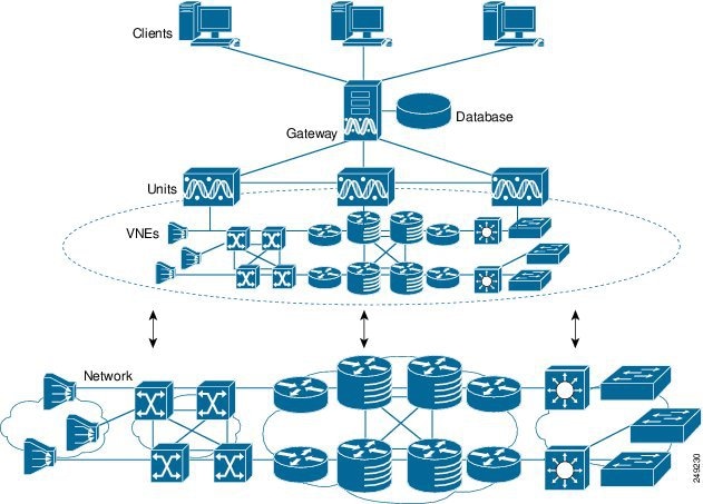
Gateway Layer
The Prime Network gateway layer includes the gateway server, through which all Prime Network GUI client, OSS, and BSS applications access the Prime Network fabric. Each client connects to its designated gateway. The gateway enforces access control and security for all connections and manages client sessions. It maintains a repository for system settings, topological data, and snapshots of active alarms and events. The gateway also maps network resources to the business context, which enables Prime Network to contain information (such as VPNs and subscribers) that is not directly contained in the network and display it to northbound applications.
The gateway AVM process is AVM 11, which supports the majority of foundation services, including inventory and topology snapshots, VNE communications, authentication, authorization, and accounting (AAA) and administration services, session management, plug-ins, alarms, business objects, maps, and application services.
VNE Layer (Units, AVMs, and VNEs)
The Prime Network VNE layer comprises the interconnected fabric of units, AVMs, and VNEs.
Each unit manages a group of network elements. Units should be distributed in a way that ensures proximity to their network elements. Prime Network also provides a unit server high availability mechanism to protect the system in case a unit malfunctions. Unit availability is established in the gateway as the gateway runs a protection manager process which continuously monitors all units in the network. If the protection manager detects a unit that is malfunctioning, it automatically signals one of the standby servers in its cluster to load the configuration of the faulty unit (from the system registry), and to take over all of its managed network elements. You can designate a unit to act as an active or standby unit when you add it during installation.
AVMs are Java processes that provide the necessary distribution support platform for executing and monitoring multiple VNEs. As Java processes, AVMs have dedicated memory for executing and monitoring multiple VNEs in a distributed manner. AVMs and VNEs are generally distributed among unit servers in the system, but they can also reside together on a Prime Network gateway server.
Some AVMs are reserved , which means they are used by the system; other AVMs are user-created , which means they are used to host devices (VNEs). Prime Network contains a watchdog protocol process that monitors the AVMs, and restarts them if they have stopped. This is called AVM protection.
VNEs are autonomous, miniature engines that operate independently and in parallel. Each VNE is in charge of a single device. It maintains a real-time virtual model of the device, including its physical and logical inventories, and its connectivity references to its immediate neighbors. When a VNE is created, it identifies the NE and begins discovery after receiving the IP address and credentials of the NE. Collectively the VNEs maintain the complete inventory and connectivity information of the network. VNEs share information through peer-to-peer messaging that enables intelligent, scalable, cross-network processing, such as discovering connectivity, end-to-end service tracing, and topology-based correlation and root cause analysis.
It is important to understand the difference between a VNE entity and a device entity in Prime Network.
- Device entities are displayed on maps in the Vision GUI client. From here you can view the device physical and logical inventory, and network-related connections.
- VNE entities are displayed in the Administration GUI client. A VNE entity in the Administration GUI client corresponds to a device entity shown on a Vision map. From the Administration GUI client you can check a VNE to see if there are any communication or modeling issues between the VNE and the device it represents.
Managing the network through a fabric of autonomous VNEs ensures scalability by avoiding any single computational bottleneck; it enables the Prime Network platform to grow along with the network. VNEs divide the network into modular self-contained blocks. The VNE layer accommodates network changes by adding or upgrading VNEs whenever network changes occur.
Essentially, the unit VNE fabric builds a virtual mirror of the real network, as shown in Figure 3-2.
Figure 3-2 VNEs Create a Model of the Network

Getting Basic Information (Gateway, Unit, AVM, and VNE)
These topics explain how you can get the properties and current status of the Prime Network components:
- Getting Gateway Status and Property Information
- Getting Unit Status and Property Information
- Getting AVM Status and Property Information (Including Reserved AVMs)
- Getting VNE Status and Property Information
Getting Gateway Status and Property Information
The best practice for getting gateway information is to right-click the gateway in the navigation area and choose Properties , as shown in Figure 3-3. The log for the gateway process is stored in NETWORKHOME /Main/logs/11.out.
Figure 3-3 Gateway Status and Properties

The IP address of the gateway as defined in Prime Network Administration. |
|
The total physical memory on the gateway server machine (both free and in use). |
|
Of the total physical memory on the gateway (also considered a unit to Prime Network), the amount of memory that is available to be assigned to other AVMs. Memory assigned to AVMS, whether the AVM is running or not, is considered unavailable. |
|
The total physical memory that would not be available if running AVMs used all of their assigned memory. (AVMs often use less that their assigned memory.) This total reflects the number for both reserved and user-created AVMs. |
|
The total physical memory that would not be available if all AVMs on the gateway used all of their assigned memory. (AVMs often use less that their assigned memory.) This total reflects the number for both reserved and user-created AVMs. |
|
The cluster group that the gateway belongs to as part of the unit high availability mechanism and cannot be modified. If any units in the cluster go down, a standby unit will take over. By default, the gateway is assigned to the default-pg protection group. |
|
Indicates that the gateway is using AVM protection and unit server high availability. These are the mechanism that ensure redundancy. They cannot be modified. See Overview of Unit and Process Protection. |
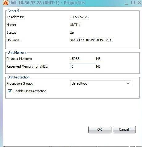
Getting Unit Status and Property Information
Units are created during the installation process as described in the Cisco Prime Network 4.3.1 Installation Guide . Like the gateway, the best practice for getting unit information is to right-click a unit in the navigation area and choose Properties . Table 3-1 provides an example of unit properties.
Figure 3-4 Unit Status and Properties
|
The IP address of the unit server. Units behind firewalls or NAT devices will have an IP address of 0.0.0.# . This is an artificial IP address used by the gateway server. |
||
The unit is reachable, but was stopped. This is the status when an networkctl stop command is issued. The unit is both operationally and administratively down. |
||
The unit cannot be reached by the gateway, so it cannot be managed. |
||
The unit was disconnected from the gateway (normally a temporary measure to address a problem). See Stopping Unit Communication with the Gateway (Disconnect). |
||
|
The total physical memory on the unit server machine (both free and in use). |
||
|
Of the total physical memory on the unit, the amount of memory that is available to be assigned to VNEs. |
||
|
If checked, the unit is using unit server high availability. The Protection Group drop-down lists shows the cluster that the unit belongs to. If any units in the cluster go down, a standby unit will take over. By default, all units are assigned to the default-pg protection group. |
||
|
Indicates that the gateway is using AVM protection and unit server high availability. These are the mechanism that ensure redundancy. This should always be enabled. See Overview of Unit and Process Protection. |
||
Getting AVM Status and Property Information (Including Reserved AVMs)
When you select a gateway server or unit in the navigation tree, Prime Network displays all of its member AVMs. This includes reserved AVMs and user-created AVMs.
Reserved AVMs
Reserved AVMs (also called system AVMs ) are created by Prime Network and used for backend purposes. These AVMs cannot be edited or deleted. Some reserved AVMs are only installed on the gateway; others are installed on both the gateway and units. For example, in Figure 3-5, the gateway server has 10 system and user-created AVMs.
Figure 3-5 Listing all AVMs in a Unit or Server
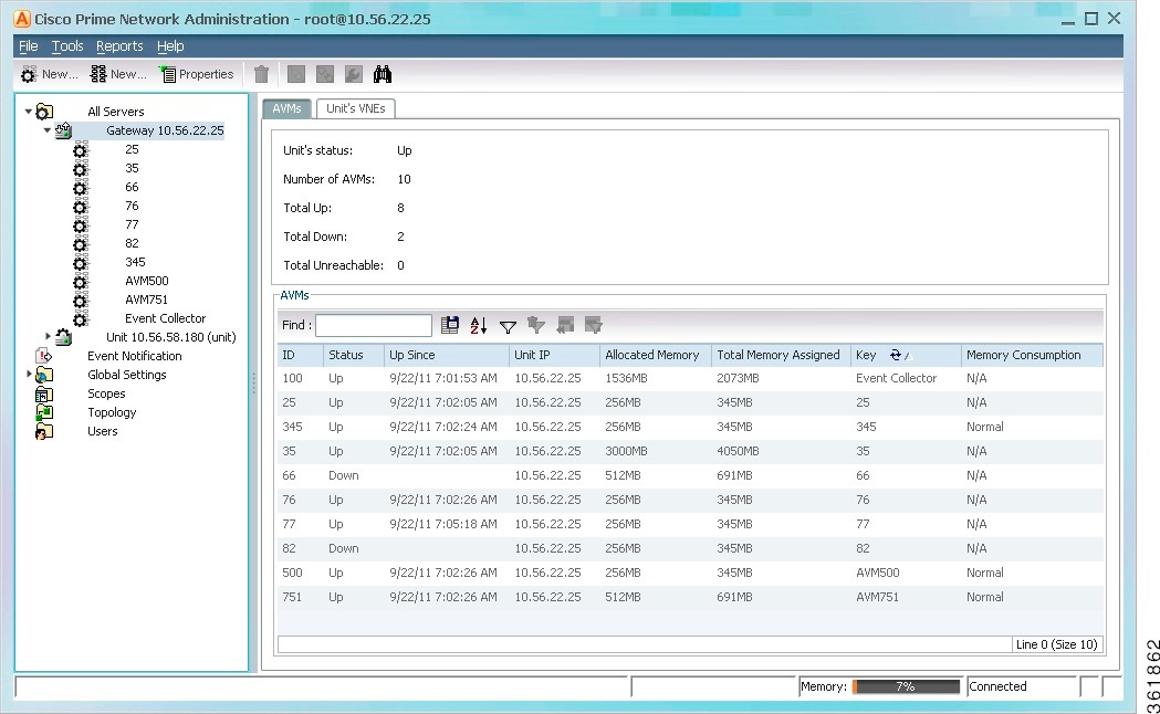
Table 3-2 lists the AVMs that are reserved by Prime Network. You can check the status of these AVMs either using the GUI client or networkctl .
|
Can be checked using1...
|
|||||
|---|---|---|---|---|---|
High Availability/Switch AVM—Enables communication between the unit and other units, as well as the gateway. See Managing Redundancy for Units and Processes. |
|||||
Gateway AVM—Manages the gateway server and other processes running on it. See Managing Prime Network Components: Gateways, Units, and AVMs. |
|||||
Auto-Add AVM—Used by auto-add mechanism. See How VNE Auto-Add Works. |
|||||
Fault Agent AVM—Processes event information (in each unit), including updates and new correlation information, and generates new tickets when required. See Controlling Event Monitoring. |
|||||
Service Discovery AVM—Performs Carrier Ethernet service discovery (for example, EVC). For large-scale deployments with many services, the memory for AVM 35 can be increased. (For information on how to do this and other capacity planning tasks, contact your Cisco account representative.) |
|||||
Compliance Manager AVM—Checks device configurations to ensure they comply to policies. For more information, refer to the Cisco Prime Network 4.3.1 User Guide . |
|||||
Operations Reports AVM—Saves device inventory information to the Infobright database. It is enabled when an Infobright database is installed. For information on the Infobright database and Operations Reports, refer to the Cisco Prime Network 4.3.1 Operations Reports User Guide . |
|||||
Infobright database sync AVM—In gateway high availability deployments, synchronizes information between the local and remote Infobright databases. For more information, refer to the Cisco Prime Network 4.3.1 Gateway High Availability Guide . |
|||||
VNE topology AVM—Distributes topology information among VNEs. |
|||||
TFTP Server—Reserved for use by Prime Network Change and Configuration Management (when installed) if using TFTP. |
|||||
Management AVM—Manages the unit and its AVM (if there are no separate units, it manages the gateway and its AVMs). |
|||||
Event Collector AVM—Listens for and receives traps and syslog notifications from devices, and forwards them to corresponding VNEs. See Controlling Event Monitoring. |
|||||
|
1.You can also check AVM status using the Monitoring (graphs) tool; see Checking Overall System Health with the Monitoring (Graphs) Tool. |
AVM Properties
If you select All Servers and click the All AVMs tab, Prime Network displays all of the user-created AVMs in the entire system. For example, in Figure 3-6, the entire system has 10 user-created AVMs.
Figure 3-6 Listing all User-Created AVMs in Prime Network
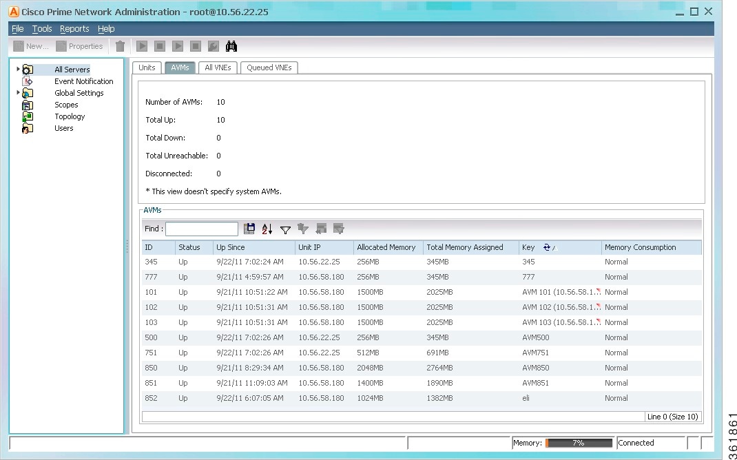
The fields in the AVM table are described in Table 3-1 . To see which fields are editable, right-click an AVM and choose properties (refer to Table 3-4 ).
|
The AVM ID. This cannot be changed once the AVM is created. If Prime Network created the AVM using auto-add, it used the first available 3-digit number starting at 101. |
||
The AVM process is reachable, was loaded, and has started. This is the status when the AVM is created (and you selected Activate Upon Creation), and no problems are encountered. |
||
When a Stop (command) option is issued and, while the command is being run, some processes are still running, the status of the AVM is Shutting Down. |
||
The AVM process is reachable, but was stopped. This is the status when a Stop (command) is issued. The AVM is both operationally and administratively down. |
||
The AVM process cannot be reached by the gateway, so the AVM cannot be managed. |
||
The AVM is on a unit that was disconnected from the gateway (the unit has a Disconnected status). |
||
|
IP address of the parent unit server. Units behind firewalls or NAT devices will have an IP address of 0.0.0.# . This is an artificial IP address used by the gateway server. |
||
|
The total physical memory being used by the AVM. For user-created AVMs, this is 1500 MB by default. You can also edit the setting from the AVM properties dialog. If your change may cause unit memory issues, Prime Network will generating a warning message, but you can still proceed (however, Prime Network will generate a System event). You must restart the AVM for changes to take effect. |
||
|
The total virtual memory dedicated to the AVM when it was created. By default, user-created AVMs are assigned 1900 MB (the 1500 MB default allocated memory plus 400 MB). The assigned memory is normally higher the an allocated memory because there be extra memory available beyond what is currently be used. If you manually create an AVM and specify its allocated memory, the assigned memory will be your specified value plus 400 MB. |
||
|
The name of the AVM as defined in Prime Network. The key uniquely identifies an AVM in the Prime Network system, across all units, thus enabling a transparent failover scenario in the system. Note that the key can be different from the ID (AVM number); the ID is listed in the AVMs table when you select the parent unit or gateway server. This field is editable but requires an AVM restart. |
||
AVM ID _ nnn (where nnn is a unique designator assigned by Prime Network) |
||
|
Indicates whether the AVM has surpassed its warning memory consumption warning threshold. Supported values are: |
||
The AVM is a system AVM; memory consumption is not applicable. |
||
The AVM has exceeded its threshold and you should adjust its load. See Changing the Gateway IP Address in Prime Network. |
||
If you right-click a specific AVM and choose Properties , you can view the following additional details the AVMs. If you edit any fields, you must restart the AVM to apply your changes.
|
If the check box is checked, AVM protection (the watchdog protocol) is enabled. For more information, see Managing Redundancy for Units and Processes. Note It is highly recommended that you do not disable this option if unit server high availability is enabled. If you change the option when the AVM is up, you must disable and re-enable the AVM for the change to take effect. |
||
When moving an AVM, its status has a bearing on whether the process is automatically restarted. If its status is Up, it is restarted; if its status is down, it is not restarted. For more information about moving AVMs, see Moving and Deleting AVMs.
You can also get AVM diagnostic information using the Monitoring (graphs) tool. The tool provides a drill down feature so you can check user-defined AVMs health, errors or exceptions, and GC prints. See Checking Overall System Health with the Monitoring (Graphs) Tool.
Getting VNE Status and Property Information
VNEs are the central building blocks of the Prime Network system. Each VNE is an autonomous, miniature engine that is in charge of a single device. But a VNE is an entity that only exists within Prime Network; the real device is a separate entity. These topics explain how to get basic status and property information for a VNE.
The VNE process must be completely functional in order for Prime Network to properly model and monitor a device. This administrative condition of the VNE is expressed through the VNE status .
For information on VNE investigation, modeling, and communication, and how to add or change VNEs, see Configuring Device VNEs and Troubleshooting VNE Problems.
VNE Status
Figure 3-7 illustrates the status of VNEs that reside on a selected AVM.
Figure 3-7 VNE Status in AVM Window

This status is entirely user-directed, and is controlled by right-clicking the VNE and choosing an action. Table 3-5 lists the status you may see in a table of VNEs.
The VNE process is reachable, was loaded, and has started. This is the status when a Start command is issued (or when you create a VNE and choose Start as its initial status), and no problems are encountered (such as an overloaded server). If you want to temporarily disable alarm processing, you can move a VNE to maintenance. The VNE status will be Up but the value for Maintenance will be True. You will manually move the VNE back to normal mode (right-click the VNE and choose Actions > Start ). |
|
A Stop (command) option was issued and, while the command is being run, some processes are still running, the status of the VNE is Shutting Down. |
|
The VNE process is reachable, but was stopped. This is the status when a Stop command is issued. The VNE is both operationally and administratively down. VNEs that were in maintenance mode will move to the Down state in the following circumstances: |
|
The VNE cannot be reached by the gateway, so the VNE cannot be managed. (Note that this is the VNE status, not the device status; the device may be fully reachable. See What is the Difference Between a VNE and a Device?.) |
|
The VNE is on a unit that was disconnected from the gateway (the unit has a Disconnected status). |
VNE Properties
VNEs can have a wide range of properties depending on how they were created. When a VNE is created, it identifies the NE by vendor, device family, device subfamily, device type and software version. Once the NE type is determined, the VNE begins discovery after receiving the IP address and credentials of a specific NE. It collects the basic inventory of the system, both physical and logical, and attempts to determine its place in the network topology.
You can get a wide range of information about a VNE by choosing its host AVM and looking at the VNEs table. Figure 3-8 shows an example of an AVM’s VNEs table in the Administration GUI client.
Figure 3-8 List of VNEs in AVM Window

To retrieve all of a VNE’s properties, launch its Properties dialog. Figure 3-9 illustrates a VNE dialog properties.
The IP address of the device as defined in Prime Network Administration. |
|
Status of the VNE: Starting Up, Up, Shutting Down, Down, or Unreachable. |
|
Indicates whether the VNE is (true) or is not (false) in maintenance mode. |
|
Indicates whether SNMP is enabled (true) or disabled (false) on the VNE. |
|
Indicates whether Telnet or SSH is enabled (true) or disabled (false) on the VNE. |
|
VNE category, such as Auto Detect, Generic SNMP, Cloud, or ICMP. |
|
Determines what data should be retrieved for each device, and which commands and protocols Prime Network should use to collect that data. |
|
The name of the polling group. The entry in this column is blank if the polling group is an instance. For information on the schemes supported by device types, refer to the Cisco Prime Network 4.3.1 Supported Technologies and Topologies . |
|
Version of the VNE device driver that the VNE is currently using. |
|
Device Package that is installed on the gateway server. You can use this and the driver file name information to verify whether a newer driver is available, which might supply additional functionality. |
|
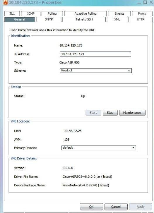
All of the VNE properties are described in detail in VNE Properties Reference. For information on how to add, manage, delete, and troubleshoot VNEs, see Configuring Device VNEs and Troubleshooting VNE Problems.
Stopping and Restarting Prime Network Components
If you stop and restart the gateway server, you stop all active queries, flows, and transactions being run on the gateway, all units, all AVMs, and all VNEs. If you make changes to a component, such as an AVM, you normally only have to restart the individual component to apply your changes. If you install a new VNE driver, you only need restart the VNE, not the hosting AVM.

Note By default, Prime Network automatically restarts when the gateway server is rebooted. To disable this behavior, see Managing Configurations with Firewalls (Device Proxy).
If you need to restart Prime Network but want to restart AVMs in a controlled manner, see Restarting Prime Network In a Gradual Manner.
Stopping Unit Communication with the Gateway (Disconnect)
Disconnecting a unit allows you to temporarily stop unit-gateway communication so you can fix the unit problem without having to reinstall the unit when you are done (units can only be added using the installation script). For example, say a unit’s Ethernet card goes down and the unit becomes unreachable. You could do the following:
1. Disconnect the unit from the gateway, and move all AVMs and VNEs to a temporary unit.
2. Fix the Ethernet card problem.
3. Reconnect the unit to the gateway.
4. Move all AVMs and VNEs back to the unit.
As this scenario shows, even if a unit is in the Disconnected state, you can still, add, delete, start, stop, and update AVMs and VNEs on the unit.
Disconnecting a unit that is part of a protection group does not trigger starting the standby unit because unit protection is also disabled on the active unit that is being disconnected. Prime Network will not allow you to disconnect a unit that is the designated standby unit.
Reconnecting the unit restarts the unit and all AVMs and VNEs. Unit information is uploaded to the gateway server, and registry information is downloaded to the unit from the gateway.
Note Before you disconnect a unit, if the Event Collector (AVM 100) is enabled on the unit, enable an Event Collector on another unit or the system will drop events. You must configure devices to forward events to the new Event Collector, and enable AVM 100 on another unit, as described in Enabling a New Event Collector on a Unit.
Step 1 In the Prime Network Administration window, select All Servers .
Step 2 Right-click the unit and choose Disconnect.
Step 3 If the unit is running (its status is Up), a warning will be displayed that says
Step 4 Confirm your choice. You can now delete the unit as described in Deleting a Prime Network Unit.
Similarly, if you want to reconnect a unit, right-click the unit and choose Connect .
Restarting Prime Network In a Gradual Manner
Note If you are using gateway server high availability, start and stop the gateway using the Red Hat application or CLI commands, not networkctl. Stopping the applications using the regular application commands without the awareness of the cluster software can cause the service group to failover.
When you use the networkctl start or restart command, all user-defined AVMs (AVMs containing VNEs) start at the same time. This can be a resource-intensive operation on a very loaded system. It can also cause unwanted side effects for systems with an external authentication server (such as TACACS). In such cases, it is better to gradually start all AVMs.
If the Prime Network system is running, you can use the Prime Network Administration GUI to bring up AVMs one by one. However, because the AVMs normally restart in a manner of minutes, this method may not give you the control you want. You can reconfigure AVMs to not restart when the system is restarted. Then you can start the AVMs manually, once Prime Network Administration is running.
Disable the user-defined AVMs on each unit, as follows.
Note Changes to the registry should only be carried out with the support of Cisco. For details, contact your Cisco account representative.
Prepare a list of the AVMs you do not want to automatically restart, and the IP addresses of the units that are hosting the AVMs.
Step 1 Log into the gateway as pnuser and change to the Main directory.
Step 2 For each AVM you do not want to auto-restart, change the registry key named enable to false using the runRegTool.sh script:
runRegTool.sh -gs gateway-IP set 127.0.0.1 “avm99/services/bsm/ avm-id /enable” false
In this example, the AVM ID is 207 and is hosted by the gateway:
#
./runRegTool.sh -gs 127.0.0.1 set 127.0.0.1 "avm99/services/bsm/avm207/enable" false
runRegTool.sh -gs gateway-IP set unit-IP “avm99/services/bsm/ avm-id /enable” false
In this example the AVM is AVM 30, and it is hosted by a unit with the IP address 172.23.240.12:
#
./runRegTool.sh -gs 127.0.0.1 set 172.23.241.12 "avm99/services/bsm/avm301/enable" false
Step 3 When you have finished reconfiguring the AVMs, restart the gateway:
#
cd $ANAHOME/Main
networkctl restart
#
Step 4 Gradually start the individual AVMs using the Prime Network Administration GUI (see Moving and Deleting AVMs).
Note You should monitor the unit’s CPU usage while starting an AVM, and only start additional AVMs when the unit CPU usage is stable.
Using networkctl to Stop and Start Components
Note By default, Prime Network automatically restarts if the gateway is rebooted. To disable this behavior, see Managing Configurations with Firewalls (Device Proxy).
You can use the networkctl command to check the status of all unit processes (including user-created AVMs), stop and restart certain AVMs, and stop and restart a unit or the gateway.
Restarting a unit stops all AVM and VNE processes on the unit, and then restarts them. Because system saves information within the process memory, restarting a unit causes some of the information to disappear. Therefore, recovering all information that was stored in the process memory prior to the restart takes as long as the longest full system polling cycle. Data that was persisted (stored in the unit) is available immediately. (Persistency is described in Changing Settings That Control VNE Data Saved After Restarts.
Keep these items in mind when restarting a unit:
- Some of the VNEs running on the unit will be reported as unreachable.
- All active queries, flows, and transactions that are currently being run within the unit’s VNEs are stopped.
Step 1 Log into the unit server as pnuser and change to the Main directory:
Step 2 Enter the following, substituting start or restart for option :
The unit begins loading. The process might take a while to complete.
For more information on working with AVMs and understanding their status, see Getting AVM Status and Property Information (Including Reserved AVMs).
Disabling Prime Network Automatic Restarts
By default, the Prime Network will automatically start whenever the gateway server is rebooted. If you wish to disable this feature, run the following procedure from the gateway. The change will be populated to all units in the system.
Step 1 Log into the gateway as pnuser and change to the Main directory.
Step 2 Issue this command to disable Prime Network from starting when the server is rebooted:
#
./runRegTool.sh -gs 127.0.0.1 set 0.0.0.0 "site/system/startup" false
(If you want to re-enable this feature, specify true .)
The change is automatically applied; you do not need to restart the gateway.
Managing Client and User Sessions
These topics explain how to use the Session Manager GUI to monitor and terminate user sessions, how to set a system-wide idle time for all client sessions, and how to configure the maximum number of client sessions that can be open at one time.
- Monitoring and Terminating User Sessions
- Configuring Global Client Idle Times and the Maximum Number of Client Sessions
Monitoring and Terminating User Sessions
The Session Manager GUI helps you manage all Prime Network GUI and NBI client sessions. You can terminate sessions and ask users to log back in, or just kill sessions completely. The Session Manager uses the HTTPS protocol and authentication method.
To open the Session Manager, enter https:// gateway_ip :6081/ana/services/session_mgr in your browser where gateway_ip is the gateway IP address. The Session Manager lists the following information about currently open sessions for that gateway.
Configuring Global Client Idle Times and the Maximum Number of Client Sessions
By default, the Prime Network gateway will not disconnect GUI client sessions regardless of how long the session has been inactive. You change this behavior and set a client inactivity timer if needed.
In addition, you can control the maximum number of clients, system-wide, that can connect to a gateway at one time. Once this number is exceeded, the gateway will refuse client connections. By default this is set to 150 connections. (User accounts also have a setting for limiting connections per user.)
The registry entry and default value are provided in Table 3-8 .
Note Do not exceed the value of 150 maximum open sessions. Doing so can negatively impact system performance.
This example changes the client session idle time to 30 minutes. When 30 minutes are exceeded, the gateway will automatically disconnect the idle clients.
Step 1 Log into the gateway as pnuser and change to the Main directory.
Step 2 To change the client inactivity timer, use this command. In this example the timer is changed to 30 minutes:
#
./runRegTool.sh -gs
gateway-IP
set 127.0.0.1 "avm11/services/sessionmanager/sessionIdleTime" 1800000
Changing the Gateway IP Address in Prime Network
Note This feature is only supported on configurations that meet both of the following criteria:
- The gateway and unit are installed on the same server.
- The system is running Linux and has an embedded Oracle database.
It is not supported on configurations with units installed on separate servers.
If the IP address of the gateway server is changed, you must also change several items in the registry so that system components can continue to communicate properly. Prime Network provides a script called change_gw_ip.pl that updates the following registry files:
- persistency.xml—Changes the entries for the main Oracle database schemas.
- avm0.xml—Changes the uplink entry between the gateway and its units (in this case, both gateway and unit are on the same server).
The script will also restart Prime Network to apply the changes across the system (including Prime Network Change and Configuration Management).
- Make sure you have the old and new IP addresses for the gateway server.
- Re-configure the devices to forward events to the new IP address of the gateway server if the Cisco Event Listener (AVM 100) is enabled and is running on the gateway server.
To update the registry with the new IP address of the gateway:
Step 1 Stop all applications that are running on the gateway server. Log in as the pnuser and run the following commands:
#
cd $ANAHOME/Main/scripts/embedded_db
#.
/emdbctl--stop
Step 2 Confirm that the embedded Oracle database is stopped. If it is not, log in as the database user and issue the following command:
ORACLE_HOME / product/ product-version /db_1/bin/dbshut
Step 3 Start the change_gw_ip.pl script as follows:
Note If you are using Prime Network with Prime Central, and you change the gateway server hostname (but not the IP address), use the --hostname_only flag with the new fully qualified domain name. (This updates the DMIntegrator.prop and ILItegrator.prop files.). The syntax is: change_gw_ip.pl --hostname FDQN
#
cd $ANAHOME/Main/scripts
#
change_gw_ip.pl
In the following example, the old IP address is 10.56.57.50 and the new IP address is 10.56.22.47.
This action can only be performed after Oracle DB and OS were updated. Continue? (y/n):
y
Please enter the old IP Address:
10.56.57.50
Please enter the new IP Address:
10.56.22.47
Updated: /export/home/pn41/Main/registry/persistency.xml

Updated: /export/home/pn41/Main/registry/ConfigurationFiles/0.0.0.0/persistency.xml

Updated: /export/home/pn41/Main/registry/ConfigurationFiles/127.0.0.1/persistency.xml

Updated: /export/home/pn41/Main/registry/ConfigurationFiles/avm0.xml
Step 4 If you want to undo the changes, cancel the procedure as follows (otherwise, proceed to the next step):
GW and units are about to be restarted. Continue? (y/n):
n
Would you like to undo the changes? (y/n):
y
Stopping Units...

Updated: /export/home/pn41/Main/registry/persistency.xml

Updated: /export/home/pn41/Main/registry/ConfigurationFiles/0.0.0.0/persistency.xml

Updated: /export/home/pn41/Main/registry/ConfigurationFiles/127.0.0.1/persistency.xml

Updated: /export/home/pn41/Main/registry/ConfigurationFiles/avm0.xml

Done.
Step 5 To commit the changes, restart the gateway:
GW and units are about to be restarted. Continue? (y/n):
y
Stopping Units...

Stopping AVMs...done.

Restarting GW...

Stopping AVMs...done.

Starting MVM...............................................Done.

Starting Gateway...........................................Done.
Step 6 Verify that Prime Network is running properly:
#
cd $ANAHOME/Main
#
networkctl status
Step 7 Verify that the embedded Oracle database is running properly using your preferred method.
Managing Configurations with Firewalls (Device Proxy)
Prime Network can manage gateways, units, and devices that are behind firewalls, as long as the system is configured as described in this topic.
Servers and Units Behind Firewalls
If a gateway server is behind a firewall, you must open ports on the firewall.
If any unit servers are located behind firewalls or NAT devices:
- The unit is displayed in Prime Network Administration GUI client with an IP address of 0.0.0.# . This is an artificial IP address used by the gateway server.
- You do not have to open special ports for the units. The units will always initiate communications.
- An Event Collector (AVM 100) must be running on at least one of the units behind the firewall. If you have several NAT sites with similar configuration, an Event Collector must be running on at least one unit at each site.
Managed Devices Behind Firewalls
If there is a firewall between a GUI client and a managed device, all attempted Telnet connections to the device will fail. For these cases Prime Network provides a device proxy feature that, when enabled, routes connections from the client through the gateway server and the appropriate unit in order to reach the device. Supported connections are Telnet, Ping, and SSH.
Once this solution is configured, if a user right-clicks a device in a Prime Network Vision map, the user will see the menu items displayed in Figure 3-10.
Figure 3-10 Right-Click Menu When Device Proxy Feature is Enabled (Prime Network Vision)
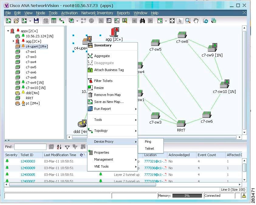
Choosing Device Proxy > Ping or Device Proxy > Telnet launches an SSH client that logs into the gateway server and passes the device and unit IP address to the gateway. The gateway then opens another SSH client to the unit, and the unit executes the protocol command on the selected device. The session then opens on the user’s client, and the user has to enter the appropriate password (configured in the following procedure). You can optionally configure the feature so that the user does not have to enter a password; in that case only SSH keys are used for authentication. All ping sessions are closed after 120 seconds’ expiration.
Configuring this solution consists of the following steps:
1. Creating the dedicated SSH user accounts on the gateway and all units using the create_ssh_user.pl script.
2. Configuring the SSH connections between the gateway and all units using the create_ssh_tunnel.pl script.
3. Enabling the feature from the Administration GUI client.
Once the feature is enabled, when a user logs into a Prime Network Network Vision client and connects to the gateway, the new choices will be available when the user right-clicks a device in a map.
- This procedure does not apply to configurations where a unit is also behind a firewall or NAT.
- Port 22 must be open between the client and gateway for this solution to work.
- If you are using key-based, password-less authentication, download the free SSH key generator, PuTTYgen. You will need it to generate the client-side keys.
Step 1 Log into the gateway server as root and navigate to the NETWORKHOME /local/scripts/proxy directory.
Step 2 Create the dedicated SSH user accounts on the gateway using the create_ssh_user.pl script. This creates the user (named proxy ) and SSH keys. The command uses the following format:
create_ssh_user.pl -new_user_password ssh_proxy_user_passwd [ -home_dir dir ] -ana_user ana_user
The script uses the following arguments:
For example (in this case Prime Network will use the default home directory):
#
./create_ssh_user.pl -new_user_password proxyadmin -ana_user pn41
Step 3 If your setup also has units, perform the following two steps.
a. From each unit, run the create_ssh_user.pl command (as shown in Step 2).
b. From the gateway (only), configure the SSH connections between the gateway and all units using the create_ssh_tunnel.pl script. The gateway will connect to all of the units and update the keys. The command uses the following format:
create_ssh_tunnel.pl -ana_user
ana_user
-new_user_password
ssh_proxy_user_passwd
For example, to create a dedicated SSH tunnel for the user created in Step 2:
#
./create_ssh_tunnel.pl -ana_user pn41 -new_user_password proxyadmin
The script will display a status message confirming that the authorized_keys file was created on all of the units.
Step 4 If you are using key-based, password-less authentication, generate and add the keys.
a. On your PC, generate the client-side SSH keys.
– As the proxy user, sftp to the gateway and get the file ~/.ssh/id_rsa.
– In the PuTTY Key Generator window, click Load and navigate to id_rsa.
– Click Save private key and name the file key.ppk . (Note the location because you will need this file in the next step.)
b. On the gateway, rebuild the proxy-config.jar package so it includes the key file and, if necessary, customize the config.bat system configuration file.
– Log into the gateway server as ana_user .
– Run the following command. (It creates a temporary proxy folder which you will delete later.)
#
cd $ANAHOME/Main/webstart/jars
#
jar -xvf proxy-config.jar
– Transfer key.ppk to $ANAHOME/Main/webstart/jars/proxy.
Note Transfer key.ppk as a binary file, not an ASCII file.
– If necessary, edit config.bat to reflect your proxy user and key file name.
– Rebuild proxy-config.jar so that it contains your modifications.
#
jar -cMf proxy-config.jar proxy/*
– Remove the temporary proxy folder.
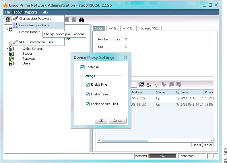
Step 5 Enable the device proxy feature in the Prime Network Administration client.To use this feature, choose Tools > Device Proxy Options as shown in Figure 3-11.
Figure 3-11 Enabling the Device Proxy Feature
Configuring the Gateway Server When a Local SNMP Agent Is Activated
If a local SNMP agent is enabled on the server on which Prime Network is installed, communication may be blocked. This is because of a forwarding rule in /etc/sysconfig/iptables that allows discovery of the SNMPv3 EngineID. If the SNMP agent is enabled on the gateway server, do one of the following:
- If you want to use SNMPv3 Informs for your managed devices, optimize the rule using the procedure that applies to your configuration. See:
– Segregated Network Where Host Is Configured With Two Interfaces (Best Practice)
– Discrete Role-Based Networks With No Physical Separation
- If you do not use SNMPv3 Informs, disable forwarding. See Disable SNMPv3 Inform Forwarding.
Before starting the procedure, be sure you understand the following terminology: The management network comprises the gateways, units, and clients (Prime Network may use SNMP to manage these entities). The managed device network comprises the routers, switches, and other types of devices that Prime Network models and manages; (Prime Network may use SNMP to model these devices).)
Segregated Network Where Host Is Configured With Two Interfaces (Best Practice)
In this scenario, one interface (eth0) is connected to the management network and the other interface (eth1) is connected to the managed device network.
Because there are no rules that control who may connect to the local SNMP agent, for greater security, you should also define rules that restrict access.
Step 2 Locate the following rule in /etc/sysconfig/iptables :
-A PREROUTING -p udp -m udp --dport 161 -j REDIRECT --to-ports 1161
-A PREROUTING -i eth1 -p udp -m udp --dport 161 -j REDIRECT --to-ports 1161
Note Because there are no rules that control who may connect to the local SNMP agent, for greater security, you should also define rules that restrict this access.
Step 4 Save your changes and restart the service by running the following command:
Discrete Role-Based Networks With No Physical Separation
In this scenario, the source network determines the rules that route the traffic to correct service. In this scenario, the management network (network 1) is 10.1.1.0/24, and the managed device network (network 2) is 10.2.0.0/16.
Step 2 Edit the file using one of the following approaches:
-A PREROUTING -p udp -m udp --dport 161 -j REDIRECT --to-ports 1161
-A PREROUTING --src 10.1.1.0/24 -p udp -m udp --dport 161 -j REDIRECT --to-ports 161

-A PREROUTING -p udp -m udp --dport 161 -j REDIRECT --to-ports 1161
-A PREROUTING -p udp -m udp --dport 161 -j REDIRECT --to-ports 1161
-A PREROUTING --src 10.2.0.0/16 -p udp -m udp --dport 161 -j REDIRECT --to-ports 1161
Step 3 Save your changes and restart the service by running the following command:
Disable SNMPv3 Inform Forwarding
If you do not use SNMPv3 Informs with your managed devices, remove the forwarding rule.
Step 2 Delete the following line from /etc/sysconfig/iptables :
-A PREROUTING -p udp -m udp --dport 161 -j REDIRECT --to-ports 1161
Step 3 Save your changes and restart the service by running the following command:
Configuring a Prime Network Integration Layer (PN-IL)
You can configure Prime Network to support Multi-Technology Operations Systems Interface (MTOSI) and 3GPP northbound interfaces (licensed separately). To do this, you must install a Prime Network integration layer.
The Prime Network integration layer allows Prime Network to expose MTOSI and 3GPP APIs over Service Oriented Access Protocol (SOAP). You can also schedule regular 3GPP inventory reports (by choosing Tools > Web Service Scheduler from the Administration or Vision GUI clients).
If you want to manage tickets using BQL or an OSS, you can disable the ticket management functions in the Prime Network Vision and Events clients. See Disabling Ticket Management in the Prime Network Vision and Events Clients.
To set up a PN-IL, refer to the instructions in the Cisco Prime Network 4.3.1 Installation Guide . For information about the 3GPP and MTOSI OSS integration and how to set up the web service scheduler, refer to the Cisco Prime Network OSS Integration Guide for MTOSI and 3GPP . Using the web service scheduler is described in the Cisco Prime Network 4.3.1 Installation Guide .
Launching Cisco Multicast Manager from Prime Network
Cisco Multicast Manager (CMM) can be integrated with Prime Network, allowing you to cross-launch CMM as follows:
- From the Vision client main menu by choosing Tools >CMM Dashboard , which will launch the CMM Dashboard.
- From the Administration client main menu by choosing Tools > CMM Configuration , which will launch CMM System Configuration.
For information on how to integrate CMM with Prime Network, refer to the Cisco Prime Network 4.3.1 Installation Guide .
Running a Command on All Units
The script rall.csh runs a given script or command on all units (not on the gateway). Log in as pnuser and execute it as follows:
where script is the script name.
Deleting a Prime Network Unit
Follow this procedure to delete a unit. You can delete units that have a status of Down, Unreachable, or Disconnected.
Delete all the VNEs and unreserved AVMs before deleting a unit; see Moving and Deleting AVMs. The reserved AVMs cannot be deleted.
Use this procedure to remove a unit:
Step 1 In the Prime Network Administration window, select All Servers .
Step 2 Right-click the unit that you want to remove, then choose Delete. A warning message is displayed.
Step 3 Click Yes to proceed or No to cancel the operation. A confirmation message is displayed.
Step 4 Click OK. The unit is deleted and is no longer displayed in the navigation pane and content area.
Creating and Configuring AVMs
These topics explain how to create, stop, start, and perform other management operations on AVMs. It also explains how the load balancing feature works, which signals you when an AVM is approaching its memory threshold.
For information on reserved (system) AVMs and how to get information on general AVM properties, see Getting AVM Status and Property Information (Including Reserved AVMs).
Adding AVMs
It is recommended, always to add AVMs automatically. Prime Network will select a unit for the AVM based on memory usage in the system. New AVMs are assigned 3000 MB of physical memory with an additional 400 MB for backend operating system tasks, for a total assigned memory of 3400 MB.
Note You can change the default memory allocation (3000 MB) for auto-added AVMs. However, to make sure your changes do not impact system performance, contact your Cisco account representative for help with AVM sizing and deployment.
When an AVM is created, it is given s number ( AVM ID ) that is unique to the unit and between 101-999. AVMs 0-100 are reserved by Prime Network (see Table 3-2 for a list of reserved AVMs). Every AVM requires a dedicated TCP port, and the port is created using the following naming convention:
For example, if you created AVM 711, it would use port 2711. The appropriate TCP port must be available or the AVM creation will fail, unless you stop the application that is using the port before you create the AVM. (A complete list of ports used by Prime Network is provided in the Cisco Prime Network 4.3.1 Installation Guide . )
Adding AVMs Manually
When you manually create an AVM, you select the unit that will host the AVM. Prime Network automatically allocates the AVM 1500 MB of physical memory (plus 400 MB for backend operating system tasks) for a total assigned memory of 1900 MB.
If desired, you can adjust the allocated memory setting. Prime Network will issue a warning message if your memory setting could potentially exceed the unit’s physical memory—that is, if all AVMs used all of their allocated memory, and that total exceeded the unit’s physical memory. Prime Network will not prevent you from continuing, but if you do continue, it will generate a System event.
Step 1 Expand the All Servers branch and select the unit or gateway that will host the AVM.
Step 2 Open the New AVM dialog box by right-clicking the required unit (or gateway), then choose New AVM. To view an existing AVM, right-click the AVM and choose Properties .
Step 3 Enter the following information to create a new AVM. The unit does not have to be up to create the AVM.
The name (a number) of the AVM as defined in Prime Network. It must be a unique number on the unit, between 101-999. AVMs 0-100 are reserved and cannot be used. The AVM will use the TCP port ( AVM_nnn + 2000). For example, if you create AVM 711, port number 2711 will be dedicated to that AVM. The appropriate TCP port must be available or the AVM creation will fail, unless you stop the application that is using the port before you create the AVM. (A complete list of ports used by Prime Network is provided in the Cisco Prime Network 4.3.1 Installation Guide . ) |
|
A string that uniquely identifies an AVM in the Prime Network system, across all units, thus enabling a transparent failover scenario in the system. The key is displayed as AVM ID _ nnn, where nnn is an designator assigned by Prime Network for tracking purposes. |
|
The memory you expect the AVM will use. This is normally 1500 MB. (The assigned memory is always the allocated memory + 400 MB.) |
|
Loads the AVM into the bootstrap of the unit. This changes the administrative status of the AVM to Up and ensures that the AVM is loaded on subsequent restarts of the unit. By default this option is not checked, and the newly created AVM has an administrative status of Down. |
|
By default this check box is checked, enabling the watchdog protocol on the AVM. For more information, see Managing Redundancy for Units and Processes. |
Step 4 Click OK. The new AVM is added to the selected unit, is displayed in the content area.
Configuring the Reserved Memory for VNEs
Prime Network calculates the initial value for reserved memory for VNEs based on the physical memory available in gateway and in every unit. Based on the initial value, AVMs are automatically generated. You can change this value to increase or decrease the number of AVMs auto generated in the Gateway or Unit.
To change the reserved memory value for VNEs, perform the following tasks:
Step 1 Choose Start > Programs > Cisco Prime Network > gateway-ip > Prime Network Administration to launch the Webstart client. You have to enter your user credentials.
Step 2 Right click the Gateway or Unit and choose Properties.
Step 3 In the Properties window, configure a value to reserve memory for the VNEs based on which the AVMs are automatically created.
Note You should ensure that sufficient physical memory is available in the Gateway or Unit when increasing the value for Reserved Memory for VNEs.
Note When the reserved memory for VNEs decreases, the redistribution of VNEs is initiated automatically.
Moving and Deleting AVMs
You can move user-created AVMs from one unit to another unit. AVMs 0-100 are reserved and cannot be moved.
Note If the unit hosting an AVM is down, disconnect the unit before moving the AVMs. See Stopping Unit Communication with the Gateway (Disconnect).
After an AVM is moved, it is reloaded, maintaining the status it was in before the move. The only exception is if a VNE was in maintenance mode. After the move, these VNEs will be in the Down state and the Maintenance indicator (in the AVMs window) will change to false .
Alarm persistency information is saved when you move an AVM to another unit. For more information, see Changing Settings That Control VNE Data Saved After Restarts.
When you delete a running AVM, the AVM is stopped and then removed. AVM registry information in the specified unit is deleted. Prime Network will not allow you to stop an AVM if any VNEs are running on the AVM. You cannot delete reserved AVMs (see Table 3-2 for a list of reserved AVMs).
Step 1 In Prime Network Administration, right-click the selected AVM, then choose Move AVM.
Step 2 Select the unit where you want to move the AVMs and click OK. The AVM is moved and now appears beneath the selected unit.
Note Because the system is asynchronous, changes may not appear in the GUI immediately. It may be a few minutes until the GUI client receives a notification from the server and is updated.
For information about moving VNEs, see Moving VNEs to Another AVM.
Before you delete and AVM, remove all VNEs from the AVM, or the operation will fail. See Deleting VNEs.
Step 1 Select the required AVM in the navigation tree. You may select multiple rows.
Step 2 Right-click to display the menu, then choose Delete. A warning message is displayed.
Step 3 Click Yes and OK. The AVM is deleted from the selected unit.
Note Because the system is asynchronous, changes may not appear in the GUI immediately. It may be a few minutes until the GUI client receives a notification from the server and is updated.
Checking Overall System Health with the Monitoring (Graphs) Tool
Whenever a System event of note occurs, it is displayed in the Events GUI client. This includes a variety of events, such as an AVM not responding, events being dropped, a unit switching on due to a failover, and many others. You can also create reports that can generate system information you want. For more information, refer to the Cisco Prime Network 4.3.1 Operations Reports Guide .
Prime Network also provides a web-based Monitoring tool that tracks how the gateway, units, and individual AVMs are operating—Java heap, dropped messages, CPU usage, and so forth. This information is provided in graphical form and you can use it to locate and diagnose problems.
Figure 3-12 shows the default page that is displayed when you first log into the Prime Network Monitoring tool; it is called the MC Loads page.
Figure 3-12 MC Loads Page—All Servers (Default)
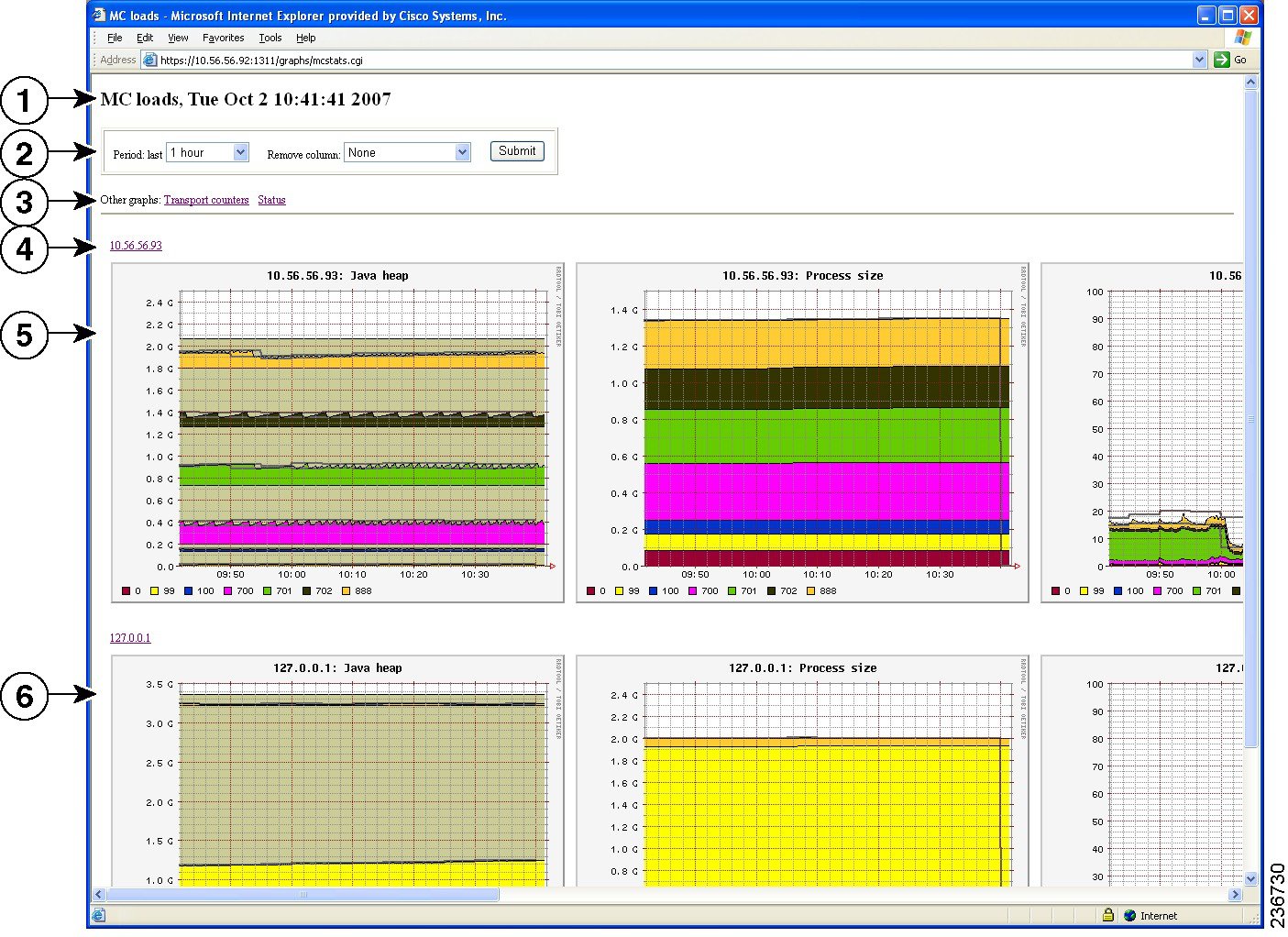
Types of Information You Can Get
The MC Loads page is generally the most useful source of information because it provides a wide variety of diagnostic information:
What Do the Colors and Indicators Mean?
When you click an IP address from the main MC Loads page (illustrated in Figure 3-12), Prime Network Monitoring displays a drill-down page for the specific server. Figure 3-13 illustrates a drill-down page for the unit server with the IP address 10.56.56.93. The first row displays a combined AVM graph, and the following rows display individual AVM information.
Figure 3-13 MC Loads Page—Drill-down to Specific Server
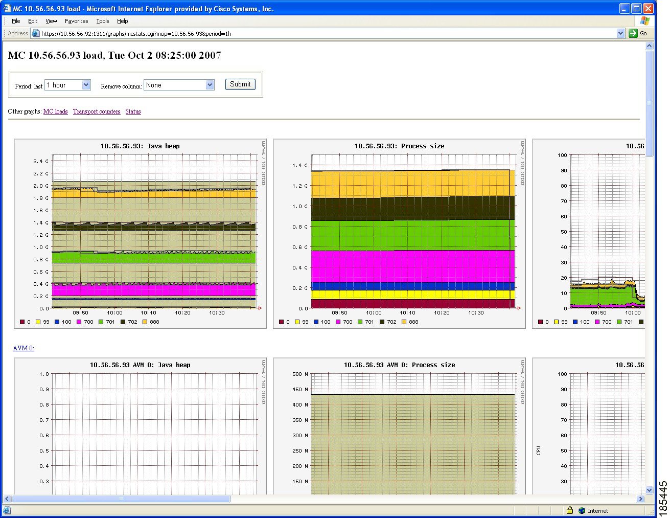
All graphs have two horizontal grey lines that mark the highest and lowest values that were collected during the sampling period. The graph itself represents the average of those values.
Figure 3-14 Grey Line Indicators in the MC Loads Graphs

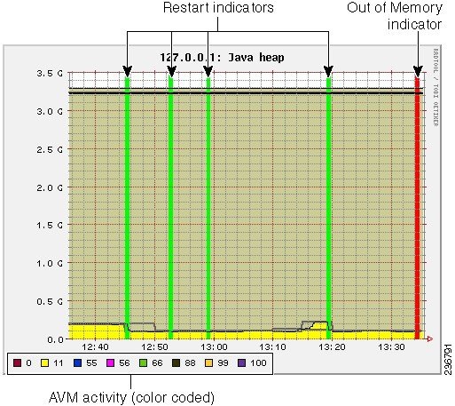
Figure 3-15 illustrates some other indicators you may see on MC Loads graphs:
- A color-coded list of AVMs on the server (gateway or unit). These appear in composite graphs, which represent behavior for AVMs on a server. The list is provided below the graph.
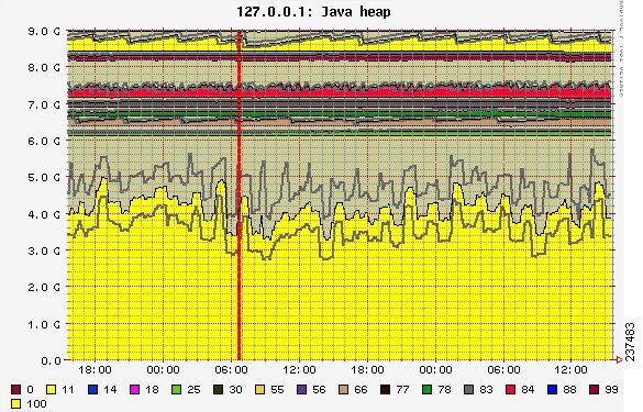
- On the Java heap graph, an out-of-memory indicator (a red vertical line) is displayed when an AVM runs out of memory. This is displayed in any graphs that provide Java heap information.
- On all graphs, a restart indicator (a green vertical line) shows when a specific AVM, or the entire server, was restarted.
Figure 3-15 Color Indicators in the MC Loads Graphs
Finally, any breaks in the data (blank vertical areas in the graph) mean that data could not be collected for that period.
Using the Monitoring (Graphs) Tool (Examples)
The web-based tool uses the username admin; the password is configured by the network-conf script during installation. You can change the username and password as described in Changing Password for Monitoring (Graphs) Tool). When you log in for the first time, download and install the security certificate. The tool uses the HTTPS protocol and authentication method.
To access the Prime Network Monitoring tool:
Step 1 Enter https:// gateway_ip :1311/graphs in your browser where gateway_ip is the gateway IP address.
A security alert is displayed regarding the site certificate.
Step 2 Click Yes , and enter the username and password.
By default, the tool displays load statistics collected during the past hour for the gateway and unit servers (the MC Loads graphs; see Figure 3-12). You can select a sampling period by choosing from the Period drop-down list and clicking Submit .
The following are some examples of how you can use the MC Loads page:
- Check the Java heap on AVM 11 on the gateway server as in indicator of gateway memory usage.
- Drill down to specific user-defined AVMs (that are hosting VNEs) to examine their health, look for errors or exceptions, and watch GC prints.
- Check the Dropped Messages graph of each unit and gateway, paying special attention to AVM 25 (the Event Persistence AVM, which would indicate drops related to event handling).
- Ensure that the GC is not taking more than 20-30 seconds (except at system startup).
The following topics provide examples of some of these uses and how to interpret the graphs on the MC Loads page.
For memory consumption, we recommend that 30% of the AVM memory remain free (in a steady state). The Java heap graph provides a visual way to check this rate. The following example shows that approximately 15% of the memory is available.
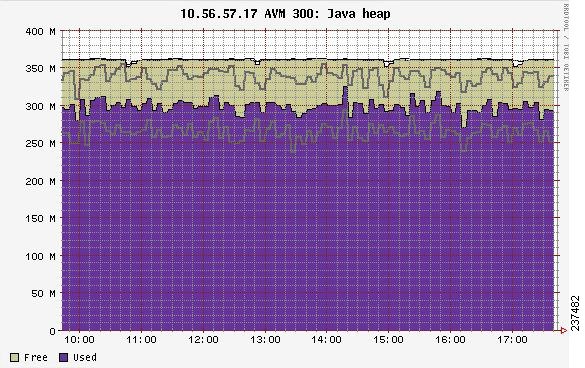
Stable memory consumption, or a constant sawteeth-shaped graph, reflects a healthy AVM. The sawtooth graph indicates the normal behavior of the Java GC, which releases unused objects on a regular basis. This behavior is expected but should not be followed by an overall growth in the memory consumption.
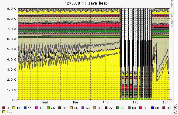
Few unique cases to consider when looking at Prime Network heap graphs:
- Very high and wide sawtooth—The AVM has extra memory available for allocation; GC runs in a low priority thread and is triggered as less memory is available. A suggested response is to add more VNEs to the AVM in a gradual manner, monitoring the AVM memory usage during the process.
- Very sharp sawtooth over a short period of time—The system is attempting to deallocate memory and is triggering GC very frequently. This may result from an AVM being too overloaded with VNEs, or specific VNEs being very large and busy. Depending on your use case, suggested responses are to allocate more memory to the AVM, reduce the number of VNEs in the AVM, or reduce the VNE polling cycles.
A gradual increase in the graph indicates that the AVM is using increasingly more memory. If there was no change to the AVM content, or to the network managed by the VNEs in the AVM, this may indicate a memory leak. In the following example, there is a memory leak in AVM 11.
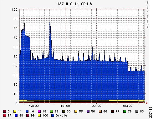
In this example, the system is configured with an embedded Oracle database and the Oracle process is causing high CPU usage.
Note In this example the Oracle process is experiencing a high CPU event. However, at system startup, it is also normal for AVMs to consume 100% of the CPU for a short period of time.
Fatal AVM Error (AVM Restart) Example
This example shows a fatal AVM error that caused an AVM restart. Common causes of this problem are out-of-memory errors and core dumps.
Changing Monitoring Tool Sampling Periods and Refresh Settings
The following table shows the different sampling rates for the data that is collected, based on their age. Data is discarded after 28 days.
You can change the graph display by entering additional parameters in the browser URL field, in an HTTP GET format. Table 3-9 describes the parameters you can use, along with examples.
Tracking System-Related Events
The following table shows from where you can get historical information on events that occurred on the gateway, units, AVMs, and VNEs.
|
Starting, stopping, adding, deleting and editing components (units, AVMs, VNEs) |
AVM and other appropriate log files (see Log Files Reference) The following reports, which you can launch from the main menu by choosing Reports > Run Report > Events Reports > Detailed Non-Network Events : |
 Feedback