- Setting Up Prime Network and Using Prime Network with Cisco Prime Central
- Managing the Prime Network Software Image, Features, and Backups
- Managing Prime Network Components: Gateways, Units, and AVMs
- Configuring Device VNEs and Troubleshooting VNE Problems
- Managing Redundancy for Units and Processes
- Controlling Device Access and Authorization Using Device Scopes
- Managing User Accounts and Authentication
- Managing the Oracle Database and System Data
- Controlling Event Monitoring
- Managing Device Configuration Operations
- Managing System Security
- Changing VNE Polling, Reachability, Discovery, and Persistency and Working with Unmanaged Segments (Cloud VNEs)
- Configuring Devices So They Can Be Properly Modeled and Managed by Prime Network
- Changing System Defaults in the Registry
- Prime Network Log Files
- VNE Properties Reference
Cisco Prime Network Administrator Guide, 4.3.1
Bias-Free Language
The documentation set for this product strives to use bias-free language. For the purposes of this documentation set, bias-free is defined as language that does not imply discrimination based on age, disability, gender, racial identity, ethnic identity, sexual orientation, socioeconomic status, and intersectionality. Exceptions may be present in the documentation due to language that is hardcoded in the user interfaces of the product software, language used based on RFP documentation, or language that is used by a referenced third-party product. Learn more about how Cisco is using Inclusive Language.
- Updated:
- January 19, 2017
Chapter: Configuring Device VNEs and Troubleshooting VNE Problems
- What is the Difference Between a VNE and a Device?
- Checking Device Discovery, VNE Status, and VNE States
- Stopping, Starting, and Moving VNEs to Maintenance Mode
- Adding Devices to Prime Network
- Adding New Device Support with Device Packages
- Changing a VNE IPAddress and Other VNE Properties
- Moving VNEs to Another AVM
- Deleting VNEs
- Assigning VNEs Automatically in Prime Network
- Troubleshooting Device Connectivity Issues (VNE Communication States)
Configuring Device VNEs and Troubleshooting VNE Problems
VNEs are the building blocks of Prime Network model because each VNE maintains a real-time model of a single device, and together, VNEs maintain a model of the entire network. These topics focus on VNEs—how devices are discovered by VNEs, how to check and troubleshoot VNE problems, and how to make changes to VNEs. Adding Devices to Prime Network, explains the various methods you can use to create VNEs and thus add devices to the model, including how to decide which method is best for your configuration.
- What is the Difference Between a VNE and a Device?
- Checking Device Discovery, VNE Status, and VNE States
- Stopping, Starting, and Moving VNEs to Maintenance Mode
- Adding Devices to Prime Network
- Adding New Device Support with Device Packages
- Changing a VNE IP Address and Other VNE Properties
- Moving VNEs to Another AVM
- Deleting VNEs
- Assigning VNEs Automatically in Prime Network
- Troubleshooting Device Connectivity Issues (VNE Communication States)
- Track VNE-Related Events
See these topics for step-by-step procedures for troubleshooting modeling and connectivity problems:
What is the Difference Between a VNE and a Device?
Actions you perform on VNEs are different from actions you perform on devices. It is important to understand the difference between VNEs and devices. VNEs are autonomous, miniature engines, and each VNE is in charge of a single device. The VNE maintains a real-time virtual model of the device (both physical and logical), and its connectivity references to its immediate neighbors. The VNE is an entity that only exists within Prime Network ; the real device is a separate entity . For example:
- A VNE has properties such as a VNE scheme, a VNE driver, and a VNE location. The scheme and driver determine the information that is modeled and monitored by Prime Network, and the location identifies where the autonomous engine is running and how it is connected to the gateway. These items are listed on the VNE Properties dialog which you can launch by right-clicking a VNE and choosing Properties . These properties are managed using the Administration GUI client.
- A device has properties such as a device series and model number, an NE software version, a chassis with slots, and a routing entities table. Device information and actions are managed using the Vision and Events GUI clients (Vision and Events users are normally unaware of VNEs and other backend processes). You can also see a subset of NE properties from the Administration GUI client by right-clicking an NE and choosing Inventory . (To see the complete physical and logical inventory and device events, you must use the Vision or Events GUI clients.)
Operators are shielded from much of the backend workings of the VNE because their concern is the real NE being managed. But the VNE process must be completely functional in order for Prime Network to properly model and monitor the device. This administrative condition of the VNE is expressed through the VNE status .
Checking Device Discovery, VNE Status, and VNE States
The Prime Network GUI clients provide some common information so that you do not have to switch between clients. For example, just as you can get a subset of VNE information from the Vision GUI client, you can also get a subset of device information from the Administration GUI client. The following table shows what type of information is displayed in the Administration GUI client when you right-click a VNE and choose either Properties or Inventory .
These topics explain how Prime Network discovers devices and how to check on the status of modeling and connectivity.
- Modeling and Monitoring Device VNEs
- Checking VNE General Status (Up, Down, Disconnected, Unreachable)
- Checking VNE Communication States (Connectivity)
- Checking VNE Investigation States (Modeling)
Modeling and Monitoring Device VNEs
When you add a device to Prime Network , Prime Network creates an autonomous VNE that models that single device. The VNE then uses the NE’s IP address and southbound management interfaces (such as SNMP or Telnet) to identify the NE by vendor, device family, device subfamily, device type and software version. When the NE type is determined, the VNE collects the basic inventory, both physical and logical, determines its status, and attempts to determine its place in the network topology. The VNE negotiates with peer VNEs (which represent peer NEs) to determine the connectivity and topology at different layers. This model of the network topology, device state, and device inventory is constantly being updated by the VNE, which tracks every change that occurs in the NE or in the network.
The information that the VNE collects is determined by the VNE scheme . You choose a scheme when you create a VNE. VNE schemes determine what data should be retrieved for each device, and which commands and protocols Prime Network should use to collect that data. When you create a VNE, Prime Network provides a drop-down of available schemes:
For example, devices poll with SNMP, but might also use CLI to poll additional information. Because the IpCore scheme assumes that the device is used as part of an MPLS VPN network containing P and PE devices, Prime Network therefore models these VNEs in a slightly different way. In most cases you can use the Product scheme with customer edge (CE) devices. You can designate a VNE as a core router by setting it to work with the IpCore scheme, or as an edge router by setting it to work with the Product scheme.
If you only want to model a certain set of technologies, create a custom scheme. The scheme is added to the gateway, and you can apply it to VNEs using the Administration client. See Creating a Custom VNE Scheme.
For guidance on choosing a scheme, refer to the Cisco Prime Network 4.3.1 Supported Technologies and Topologies .
VNE Communication and Investigation States
A VNE’s administrative condition is conveyed by its VNE status —for example, if you stop a VNE, its VNE status will be Down. VNE states , on the other hand, describe the degree to which the VNE has discovered and modeled a device, and the disposition of the communication between the VNE and the device it models. VNE state information is intentionally granular so that you can use it to troubleshoot problems.
Both the communication and investigation states are displayed in Prime Network Vision when you open a device properties window, as shown in Figure 4-1.
Figure 4-1 VNE Communication and Investigation States (in Prime Network Vision)
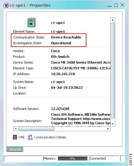

Note If a VNE was stopped, you will see a message and a refresh button at the top of the properties window. When the VNE is restarted, refresh the window to repopulate the information. If you receive an error message, it means the VNE is still down. To start the VNE, see Stopping, Starting, and Moving VNEs to Maintenance Mode.
If you want more information about the communication state, click Communication Details to get information on the status of:
- Protocols the device uses to communicate with the VNE.
- Traps and syslog forwarding from the device to the VNE.
This information is helpful for troubleshooting device reachability problems. For more information, see Checking VNE Communication States (Connectivity).
Checking VNE General Status (Up, Down, Disconnected, Unreachable)
Like AVM status, VNE status indicates the administrative condition of the VNE: Starting Up, Up, Shutting Down, Down. If the gateway server cannot communicate with the VNE, the VNE status will be Unreachable. (Remember that this is the status of the VNE, not the status of the physical device.) This information is displayed in the Administration GUI client when you select an AVM.
Starting and stopping VNEs is entirely user-directed, as explained in Stopping, Starting, and Moving VNEs to Maintenance Mode. Table 4-1 lists the possible VNE status values that you may see in a table of VNEs.
Checking VNE Communication States (Connectivity)
VNE communication states convey the status of connectivity between:
- The VNE and the device it models ( management communication)
- The VNE and the gateway ( agent communication)
When connectivity problems occur, it is normally in the management area—that is, between a VNE and a device. Devices and VNEs communicate using SNMP, Telnet, ICMP, traps, syslogs, and others—all of which determine whether a device is truly reachable. If a problem occurs, Prime Network runs tests tailored to each (enabled) protocol to determine the seriousness of the problem. Prime Network does not change the communication state to Device Unreachable unless all of the enabled device management protocols are unresponsive, and the device is not generating syslogs or traps.
Table 4-2 describes all of the possible VNE communication states. It also shows the GUI decorator for each state, where applicable. For information on troubleshooting communication state issues, see Troubleshooting VNE Communication State Issues: The Steps.
The  icon indicates a network element has been deleted (or moved). The state will show N/A for Cloud VNEs because Cloud VNEs do not represent a real network element (see Creating Connections Between Unmanaged Network Segments (Cloud VNEs and Links)).
The VNE is not responding to the gateway because it was stopped, or it was just created. This communication state is the equivalent of the Defined Not Started investigation state. |
||
The VNE is not responding to the gateway. This can happen if the unit or AVM is overutilized, the connection between the gateway and unit or AVM was lost, or the VNE is not responding in a timely fashion. (A VNE in this state does not mean the device is down; it might still be processing network traffic.) |

|
|
The VNE is starting and the initial connection has not yet been made to the device. This is a momentary state. Because the investigation state decorator (the hourglass) will already be displayed, a special GUI decorator is not required. |
||
The element is not fully reachable because at least one protocol is not operational. Note This is the default behavior. You can change the settings that determine when Cisco Prime Network moves a VNE to Device Unreachable. For more information, see Changing Reachability Settings for VNEs. |

|
|
All element protocols are enabled and connected. Note This is the default behavior. You can change the settings that determine when Cisco Prime Network moves a VNE to Device Unreachable. For more information, see Changing Reachability Settings for VNEs. |
||
The connection between the VNE and the device id down because all of the protocols are down (though the device might be sending traps or syslogs). Note This is the default behavior. You can change the settings that determine when Cisco Prime Network moves a VNE to Device Unreachable. For more information, see Changing Reachability Settings for VNEs. |

|
|
The reachability detection process is not enabled for any of the protocols used by the VNE. The VNE will not perform reachability tests nor will Cisco Prime Network generate reachability-related events. In some cases this is desirable; for example, tracking for Cloud VNEs should be disabled because Cloud VNEs represent unmanaged network segments. Because this is a user-defined mode (rather than an error or transitional mode), Cisco Prime Network does not display a decorator for this state. To troubleshoot a VNE that is in this state, check the VNE Status Details window; see Troubleshooting Device Connectivity Issues (VNE Communication States). |
Checking VNE Investigation States (Modeling)
VNE investigation states describe how successfully a VNE has modeled the device it represents. These states describe all of the possibilities in the VNE life cycle, from when the VNE is added to Prime Network, through the device modeling, until the VNE is stopped. Table 4-3 describes all of the possible VNE investigation states. It also shows the GUI decorator for each state, where applicable.
Note At any time you can restart the VNE discovery process by restarting the VNE (see Stopping, Starting, and Moving VNEs to Maintenance Mode). If you want to rediscover only a certain element within a device, go to the Prime Network Vision GUI client, open the device inventory, and right-click the element and choose Poll Now.
For troubleshooting information, see Troubleshooting Device Modeling Issues (VNE Investigation States).
The  icon indicates a network element has been deleted (or moved). The state will show N/A for Cloud VNEs because Cloud VNEs do not represent a real network element (see Creating Connections Between Unmanaged Network Segments (Cloud VNEs and Links)).
A new VNE was created and has not yet started, or an existing VNE was stopped. In this state, A VNE remains in this state until it is started (or restarted). |
||
The VNE is managed and support of its device type is being validated. |
||
The device type is either not supported by Prime Network or is misconfigured (it is using the wrong scheme, or is using reduced polling but the device does not support it). To extend Cisco Prime Network functionality so that it recognizes unsupported devices, use the VNE Customization Builder. Refer to the Cisco Prime Network 4.3.1 Customization Guide . |

|
|
The VNE is building the model of the device (the device type was found and is supported by Cisco Prime Network). A VNE remains in this state until all device commands are successfully executed at least once, or until there is a discovery timeout. |

|
|
The VNE has a stable model of the device. Modeling may not be fully complete, but there is enough information to monitor the device and make its data available to other applications, such as transactions (activation workflows). A VNE remains in this state unless it is stopped or moved to the maintenance state, or there are device errors. |
||
|
The VNE model is inconsistent with the device; however, this is often recoverable, or may indicated a small inconsistency (such as a minor inventory component not being properly modeled). Because this state can be due to a variety of reasons, check the VNE Status Details window for:
|

|
|
VNE polling was suspended because it was manually moved to this state (by right-clicking the VNE and choosing Actions > Maintenance ). The VNE remains in this state until it is manually restarted ( Actions > Start ). A VNE in the maintenance state has the following characteristics:
The VNE is moved to the Stopped state if: it is VNE is moved, the parent AVM is moved or restarted, the parent unit switches to a standby unit, or the gateway is restarted. |

|
|
The VNE model is inconsistent with the device because a required device command failed, even after repeated retries. A common cause is that the device contains an unsupported module (in which case you can extend Prime Network to recognize the module using the VNE Customization Builder; refer to the Cisco Prime Network 4.3.1 Customization Guide ). It could also be due to a more serious issue, such as an inability to reach a configured protocol on the device. |

|
|
The VNE has been stopped or deleted by the user, and the VNE is terminating its connection to the device. |

|
Stopping, Starting, and Moving VNEs to Maintenance Mode
You can start or stop a VNE, or move a VNE to maintenance mode using the Administration GUI client. When you change the status of a VNE, some information is persisted. Persisted information is data that is stored for later use. (For information on the VNE persistency mechanism, see Persistency Overview.)
Restarting a VNE reinitiates the discovery process. If you want to rediscover only a certain element within a device, go to the Prime Network Vision GUI client, open the device inventory, and right-click the element and choose Poll Now .
To change a VNE’s status, select the VNE and choose one of the following from the right-click Actions menu.
- Start —Starts the VNE process and triggers its discovery process. The VNE will move through a status of Starting Up to Up. When the VNE is Up, its process is running and it is reachable.
- Stop —Stops the VNE process. The VNE will move through a status of Shutting Down to Down. In the GUI, the Maintenance indicator in the AVMs window will display false . (If you stop a VNE that was in maintenance mode, its Maintenance indicator will change to false . This is also true if the VNE is moved, if its parent AVM is moved or stopped, if the gateway is restarted, or if it is on a unit that is switched to a standby unit.)
- Maintenance —Stops some VNE functionality so that you can perform maintenance operations without affecting the overall functionality of the active network. This is useful during planned outages such as software upgrades, hardware modifications, or cold reboots. For more details about what a VNE in the maintenance state does or does not do, see Table 4-3.
If you change the device software—for example, you install a newer version of Cisco Cat OS—you do not need to restart the VNE. The VNE will gather the new information at its next scheduled poll. However, if you change VNE software, you must restart the VNE for your changes to take effect; see Adding New Device Support with Device Packages.
The following table shows the badge used to indicate that a VNE is in maintenance mode.

To change the state of a VNE or move it to maintenance mode:
Step 1 Expand the All Servers branch, and select the required AVM in the navigation tree.
Step 2 Select the required VNE in the VNEs Properties table.
Step 3 Perform one of the following actions:
- To start the VNE, right-click Actions > Start , or click Start in the toolbar. A confirmation message is displayed. Click OK. An Up status is eventually displayed in the VNEs Properties table. You might see a Starting Up status if the gateway is overloaded or if the VNE is still being loaded. If the AVM hosting the VNE is in a Down status, the VNE status remains Starting Up until the VNE is brought up.
- To stop the VNE, right-click Actions > Stop , or click Stop in the toolbar. A confirmation message is displayed. Click OK. A Down status is eventually displayed in the VNEs Properties table. You might see a Shutting Down status while processes are shutting down.
- To place the VNE in maintenance mode, right-click Actions > Maintenance , or click Maintenance in the toolbar. A confirmation message is displayed. Click OK. A Maintenance status is displayed in the VNEs Properties table.
Adding Devices to Prime Network
These topics provide the information you need to create VNEs so that Prime Network can model and manage the devices in your network.
- Adding VNEs: The Steps
- Creating Custom VNE Schemes and VNE Defaults for SNMP and Telnet/SSH
- Choosing a Method for Adding Devices (Creating VNEs)
- Cloning an Existing Device
- Adding a New Device Type to Prime Network
- Using Network Discovery to Add VNEs
- Adding Devices Using a CSV File
Adding VNEs: The Steps
Always perform these steps before adding VNEs, regardless of which method you use. These prerequisites have a direct effect on how successfully Prime Network will model and monitor the device.
Choose a VNE scheme, or create a new one (this controls the data that is retrieved, and which protocols are used) |
Cisco Prime Network 4.3.1 Supported Technologies and Topologies . |
|
Gather all prerequisite information Tip Set up defaults for SNMP, Telnet, and SSH, and Prime Network will automatically apply those settings. See Configuring Default SNMP and Telnet/SSH Settings.
|
|
|
|
1.We recommend that you first use any SSH client application (such as UNIX SSH or OpenSSH) to determine the device SSH login sequence. Also be sure to perform the required device configuration described in Cisco StarOS Devices—Required Settings |
Creating Custom VNE Schemes and VNE Defaults for SNMP and Telnet/SSH
You can make the process of creating VNEs much easier by creating new schemes and defaults, as described in these topics:
- Creating a Custom VNE Scheme, so that VNEs will only model the information you are interested.
- Configuring Default SNMP and Telnet/SSH Settings, to specify protocol settings that will be applied by default to all VNEs.
Creating a Custom VNE Scheme
A VNE’s scheme determine what data should be retrieved from the device, and which commands and protocols Prime Network should use to collect the data. Three schemes are provided by default: Product, EMS, and IpCore; they are described in VNE Schemes. If none of these schemes meet your needs, you can create a custom VNE scheme. After it is created, the scheme is added to the Schemes drop-down menu in the Administration GUI client.
A best practice is to create a new scheme for one VNE and test it before applying the new scheme to other VNEs. This is suggested because Prime Network does not perform an validation on your chosen technologies.
You cannot delete schemes that are currently being used by any VNEs. If you edit a scheme that is being used by a VNE, the changes are only applied to the VNE if the VNE is restarted.
Step 1 Choose Global Settings > Scheme Management . All of the existing schemes are listed. You can edit all schemes except for Product, EMS, and IpCore.
Step 2 Right-click Scheme Management and choose New Customized Scheme . Prime Network displays a dialog box that lists all technologies.
Step 3 Enter a name and description, and then choose the technologies you want to model or not model by selecting them and clicking Enable or Disable . The category column can help you decide whether you should include a technology, based on the network type.
Step 4 Verify your changes, and click OK .
The new scheme is added to the list of supported schemes and is listed on the Schemes drop-down list in the VNE properties dialog.
Configuring Default SNMP and Telnet/SSH Settings
When you create default settings for the SNMP and Telnet/SSH protocols, the settings are automatically applied to all new VNEs.
Note Be sure the protocols are enabled in the VNE properties dialog box.
To configure default VNE settings, choose Global Settings > Default VNE Settings .
- Default Telnet SSH Setting are described in Telnet/SSH VNE Properties Reference.
- Default SNMP Settings are described in SNMP VNE Properties Reference.
To find out what version of SNMP or SSH a VNE is using, right-click the VNE and choose Inventory and click VNE Status .
Choosing a Method for Adding Devices (Creating VNEs)
Prime Network provides a variety of ways to add VNEs. The recommended best practice is the VNE auto-add feature. The auto-add mechanism calculates the predicted memory consumption based on a VNE’s role and type. Using that information, Prime Network assigns VNEs to units and AVMs, and balances AVM memory as the VNEs are added. You can monitor the VNEs as Prime Network adds them to the system.

Tip Start your operations from the All Servers branch (that is, right-click All Servers and choose the operation). Prime Network will use the auto-add feature.
Table 4-5 briefly describes the methods for creating VNEs and the scenarios for which they are suitable. In all of these cases, you can let Prime Network choose the best unit and AVM, or you can specify them yourself.
Note If Prime Network is installed with Cisco Prime Central, be sure to use a device’s SYSNAME as its VNE name. This allows the device to be recognized across the common inventory. Also, do not use None or All as the SYSNAME, because those names have internal meaning to Cisco Prime Central.
How VNE Auto-Add Works
When you use the VNE auto-add feature—that is, you create VNEs from the All Servers branch—Prime Network will choose the appropriate unit and AVM for the VNE. If you want the VNEs to be hosted by a specific unit, you can perform the operation from the unit (in the navigation tree), and Prime Network will only choose the appropriate AVM.
Prime Network locates the best AVM by identifying safe target AVMs . A safe target AVM has the following characteristics:
- The AVMs should be up and running.
- It should have sufficient memory to accommodate the VNEs initial memory estimation.
Auto-added VNEs are listed in the Queued VNEs tab (under All Servers ) as the VNEs are assigned to AVMs. They are removed once they are assigned to an AVM and unit.
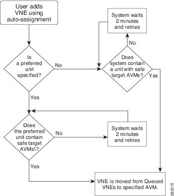
If Prime Network cannot locate an appropriate AVM, it waits two minutes and tries again. It will continue retrying until an AVM is found. Note that even when you use the auto-add feature, before the VNEs are created, you can choose a unit or AVM for a drop-down list in the VNE properties dialog.
Figure 4-2 illustrates how Prime Network identifies the best AVM and unit in the auto-add process.
Cloning an Existing Device
A clone VNE inherits all of the properties of an existing VNE (including the Device Package being used by the existing VNE). You only have to specify a different name and IP address. Prime Network will choose the best unit and AVM for the VNE, but you can override this with your own choice. Once you have created the clone VNEs, you can still edit their properties before creating them.
Make sure you have performed any required tasks that are described in Adding VNEs: The Steps. This will ensure that the VNE is properly modeled and updated.
Step 1 Choose the appropriate launch point, depending on whether you want to use the auto-add feature:
From All Servers in the navigation area, click All VNEs tab. |
|
From desired unit in the navigation area, click Unit’s VNEs tab. |
|
From desired unit in the navigation area, click the desired AVM |
Step 2 In the VNEs table, find the VNE type that you want to replicate.
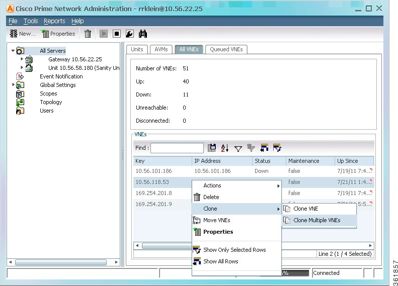
Step 3 Right-click the VNE you want to replicate and choose Clone > Clone VNE or Clone > Clone Multiple VNEs .
In Figure 4-3, the user is creating several clone VNEs based on the VNE with the key (name) 10.56.118.53. Because the action was performed while the All Servers branch is selected, Prime Network will choose the appropriate unit and AVM.
Figure 4-3 Creating a Clone VNE Using Auto-Add—Selecting the VNE
Step 4 Create the clone VNE(s).
a. In the Add VNEs from Clone dialog box, click the Add Cloned VNE icon (see Figure 4-4).
Figure 4-4 Creating a Clone VNE Using Auto-Add—Creating the Clones
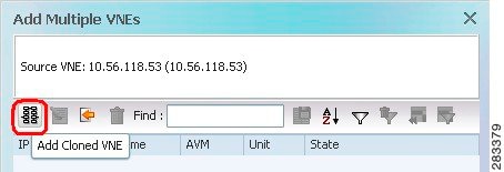
A Clone VNE dialog box is displayed. It contains all of the properties of the target VNE except for the VNE name and IP address.
b. Enter the new VNE name and IP address. When finished, click OK .
Note If Prime Network is installed with Cisco Prime Central, be sure to use a device’s SYSNAME as its VNE name. This allows the device to be recognized across the common inventory. Also, do not use None or All as the SYSNAME, because those names have internal meaning to Cisco Prime Central.
c. Repeat this step to create additional clones of the VNE. As you create more clones, they are added to the dialog box.
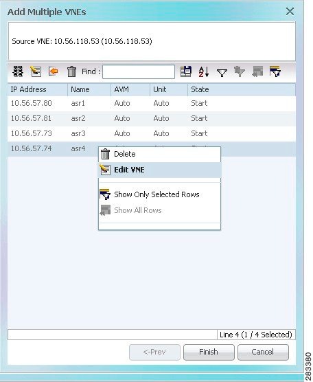
Step 5 To edit the VNE properties before creating the VNEs (for example, to specify a unit or AVM, use a different scheme, and so forth), right-click the VNE and choose Edit VNE (see Figure 4-5). If you want, you can specify the unit and AVM you want the VNE to use.
Figure 4-5 Creating a Clone VNE Using Auto-Add—Viewing and Editing the Clones
Step 6 Click Finish . To check the status of the VNEs:
a. For auto-added VNEs (the unit or AVM was selected by Prime Network), select All Servers branch and click the Queued VNEs tab. If it is empty, the VNEs have been assigned.
b. To find the VNE’s assignment, click the All VNEs tab and check the unit column.
c. Go to the unit and click the Unit’s VNEs tab to check the AVM.
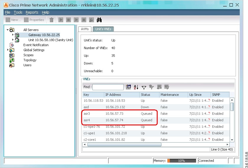
Figure 4-6 shows two new VNEs that were added to the gateway but are using AVM auto-assignment. Their assignment is pending.
Figure 4-6 Creating a Clone VNE Using Auto-Add—Checking the Assignment
Adding a New Device Type to Prime Network
If you are creating a VNE for a new device type, you should create a single VNE instance “from scratch” and test it to ensure its settings are correct. You can then clone it as described in Cloning an Existing Device.
Make sure you have performed any required tasks in Adding VNEs: The Steps. This will ensure that the VNE is properly modeled and updated.
Step 1 Choose the appropriate launch point, depending on how much control you want over the unit and AVM:
Step 2 The New VNE dialog box is displayed, opened to the General tab. The following table lists the tabs in the VNE properties window and where you can get more information on the fields in those tabs. Most VNEs only require a VNE name and IP address.
Step 3 Click Finish . Check the status of the VNEs in the VNEs table. For auto-added VNEs:
a. Select All Servers branch and click the Queued VNEs tab. If it is empty, the VNEs have been assigned.
b. To find the VNE’s assignment, click the All VNEs tab and check the unit column.
c. Go to the unit and click the Unit’s VNEs tab to check the AVM.
Using Network Discovery to Add VNEs
Note Refer to the Cisco Prime Network 4.3.1 Installation Guide for a list of supported browsers for the Network Discovery feature.
The Network Discovery feature will automatically discover your network devices by traversing the network. Use this method if you are not very familiar with the types of devices in your network. The only required information is an IP address for a seed device, and the SNMPv 2 or SNMPv 3 credentials. This information is added to a discovery profile that specifies the IP and SNMP information, along with any additional protocols or filters you want Prime Network to use. You can use multiple discovery techniques in your filter in order to locate and discover the largest number of devices.
Once your profile is complete, run the discovery job. Prime Network will use its auto-add feature to assign VNEs to AVMs. When the job is finished, a result report provides a listing of devices that were successfully located, devices that were filtered out, and devices that reported credential errors. Prime Network will not create any VNEs until it receives confirmation to proceed. After the discovery job completes, you can instruct Prime Network to create VNEs for the devices that were successfully located. For the devices with credential errors, you can correct or create a new profile, or create the VNEs manually.
Note Network discovery is supported on the following device operating systems: Cisco IOS, Cisco IOS XR, Cisco IOS XE, Cisco NX-OS, Cisco Catalyst, and Juniper operating systems. The Network Discovery feature is not supported in networks that have duplicate IP addresses.
For UCS devices, the Network Discovery feature does the following when it creates UCS VNEs:
- If Telnet is being used, it enables HTTP on the VNE and populates the HTTP credentials fields with the Telnet credentials.
- If SSH is being used, it enables HTTPS on the VNE and populates the HTTPS credentials fields with the SSH credentials.
- You have performed any necessary tasks that are described in Adding VNEs: The Steps. This will ensure that the VNE is properly modeled and updated.
- The gateway running the discovery process must be able to reach the target devices using the management protocols (SNMP and Telnet/SSH).
Step 1 Choose Tools > Network Discovery .
Step 2 Click New to create a new discovery profile. The profile determines how Prime Network can locate, identify, and communicate with devices in order to discover them. To add profile information:
Provide a unique name, and configure the discovery profile.
d. Click Sav e to save your profile. It is automatically added to the Discovery Profiles table.
Step 3 Start the network discovery by selecting the discovery profile and clicking Run .
Step 4 Choose Network Discovery > Discovery Results and choose your job. The table provides the following information; click the Refresh button at the top right of the window to update the information.
|
Discovery job name (profile name plus system-assigned number) |
||

|
||

|
Job is running or completed and encountered credential errors. Consider running the job again or creating the VNE manually. |
|

|
||
|
Number of discovered devices that are reachable and manageable using the specified credentials (before creating the VNEs, you can change the VNE scheme and reduced polling setting; Step 5) |
||
|
Number of devices that were filtered out (for a list of these devices, click the Filtered tab at the bottom of the Discovery Results window) |
||
|
Number of devices that were identified but could not be managed because of credential problems (for a list of these devices, click the Credential Errors tab at the bottom of the Discovery Results window) |
||
Step 5 To create VNEs for the reachable devices, use this procedure. Prime Network will auto-add the VNEs—that is, it will choose the unit and AVM for each VNE.
a. Click the Reachable tab at the bottom of the Discovery Results window.
b. If you want to change the VNE scheme or reduced polling setting before creating the VNEs, click the Edit button and change the settings. For information on schemes and reduced polling, refer to the Cisco Prime Network 4.3.1 Supported Technologies and Topologies .
c. Select the devices you want Prime Network to manage, and click Create VNEs . The Status column will change as the VNE goes through the creation process.
Adding Devices Using a CSV File
Using a CSV file to add VNEs is helpful when you have a large number of VNEs to create and you want to organize your information using a spreadsheet template. After you create the spreadsheet, copy it to the gateway server, and then provide it as input to the Add Multiple VNEs dialog box. Prime Network will auto-add the VNEs—that is, it will choose the unit and AVMs for the VNEs. The new VNEs will use the latest installed DP (the newest DP that is installed on the gateway or unit). If there are any errors, Prime Network will clearly display them. If any fields are left blank, Prime Network uses the defaults specified in Table 4-6 .
The CSV file supports all of the entry names listed in Table 4-6 . A general guideline is that you should supply the following entries in your file, at a minimum:
elementName,ip,SNMPEnabled,SnmpVersionEnum,adminStatusEnum ,SchemeName,avm,unitIP,ICMPPollingRate,ICMPEnabled,PollingGroup,TrapSyslogSources,TelnetSequence,telnetEnabled
The following is the text of a sample CSV file. This CSV file is also provided on the gateway server at NETWORKHOME /Main/scripts/BulkVNEImportExample.csv.
elementName,ip,SNMPEnabled,SnmpVersionEnum,adminStatusEnum,SchemeName,avm,PrimaryDomain,unitIP,ICMPPollingRate,ICMPEnabled,PollingGroup,TrapSyslogSources,TelnetSequence,telnetEnabled
m1,1.1.1.1,TRUE,1,0,ipcore,,Domain1,,50000000,TRUE,slow,,">,prompt,#,",TRUE
m2,1.1.1.2,TRUE,2,1,product,,Domain1,,856000,FALSE,default,,#,TRUE
m3,1.1.1.3 ,TRUE,2,1,,,Domain2,,,TRUE,,"129.5.6.2,55.23.6.5,9.5.2.1",">,text,#,",FALSE
m4,1.1.1.4,TRUE,1,0,,,Domain3,,,FALSE,,121.2.3.4,,TRUE
m5,1.1.1.5,TRUE ,1,0,ipcore,,Domain3,,5600000,FALSE ,slow,121.2.3.4,">,admin,#,",FALSE
|
Note If Prime Network is installed with Cisco Prime Central, be sure to use a device’s SYSNAME as its VNE name. This allows the device to be recognized across the common inventory. Also, do not use None or All as the SYSNAME, because those names have internal meaning to Cisco Prime Central. |
Mandatory field2 |
|
default (= product), product, ipcore , ems , existing custom schemes |
||
1 (start VNE)3 |
||
|
HTTP Properties4
|
||
0 =Prime Network Settings, 1 =Device Type Settings, 2 =Local Settings |
||
 Feedback