- Setting Up Prime Network and Using Prime Network with Cisco Prime Central
- Managing the Prime Network Software Image, Features, and Backups
- Managing Prime Network Components: Gateways, Units, and AVMs
- Configuring Device VNEs and Troubleshooting VNE Problems
- Managing Redundancy for Units and Processes
- Controlling Device Access and Authorization Using Device Scopes
- Managing User Accounts and Authentication
- Managing the Oracle Database and System Data
- Controlling Event Monitoring
- Managing Device Configuration Operations
- Managing System Security
- Changing VNE Polling, Reachability, Discovery, and Persistency and Working with Unmanaged Segments (Cloud VNEs)
- Configuring Devices So They Can Be Properly Modeled and Managed by Prime Network
- Changing System Defaults in the Registry
- Prime Network Log Files
- VNE Properties Reference
Cisco Prime Network Administrator Guide, 4.3.1
Bias-Free Language
The documentation set for this product strives to use bias-free language. For the purposes of this documentation set, bias-free is defined as language that does not imply discrimination based on age, disability, gender, racial identity, ethnic identity, sexual orientation, socioeconomic status, and intersectionality. Exceptions may be present in the documentation due to language that is hardcoded in the user interfaces of the product software, language used based on RFP documentation, or language that is used by a referenced third-party product. Learn more about how Cisco is using Inclusive Language.
- Updated:
- January 19, 2017
Chapter: Controlling Event Monitoring
- How Prime Network Handles Incoming Events
- Configuring the Event Collector to Listen for Incoming Events
- Configuring a Proxy Database Connection for Units Not Connected to Database
- Configuring Trap and E-Mail Notifications (Event Notification Service)
- Disabling Ticket Management in the Prime Network Vision and Events Clients
- Controlling the Vision Client Event Displays (Standard Events, History Size)
- Configuring System TCAs
- Tracking Events Related to Fault Monitoring
Controlling Event Monitoring
These topics explain how to set up and configure event monitoring in Prime Network. This includes configuring the Event Collector (which listens for incoming events), with examples for a variety of different system configurations, and how to set up trap and e-mail notifications.
- How Prime Network Handles Incoming Events
- Configuring the Event Collector to Listen for Incoming Events
- Configuring a Proxy Database Connection for Units Not Connected to Database
- Configuring Trap and E-Mail Notifications (Event Notification Service)
- Disabling Ticket Management in the Prime Network Vision and Events Clients
- Controlling the Vision Client Event Displays (Standard Events, History Size)
- Configuring System TCAs
- Tracking Events Related to Fault Monitoring
How Prime Network Handles Incoming Events
These topics provide an overview of what happens when an event is forwarded to Prime Network:
Upgraded Events and Standard Events
When a trap or syslog is sent from a device to Prime Network, it is received by the Event Collector, which runs on AVM 100. Prime Network categorizes the incoming events as follows:
- Upgraded events (also called actionable events ) are recognized by the Event Collector and have defined parsers in the Prime Network fault subsystem. In other words, these events are of interest to Prime Network. Prime Network will process these events (depending on their configuration) for deduplication, correlation, impact analysis, and so forth.
- Standard events (also called non-actionable events ) are syslogs and traps that are not recognized by the Event Collector; Prime Network has no defined parsers for standard events. However, Prime Network will perform its best effort to extract information from these syslogs and traps. Standard events are immediately saved in the Fault Database as archived events. No additional actions are taken on these events (no association, correlation, impact analysis and so on). In the past, these events were also called generic events .
Logical Flow of Events Through Prime Network
Figure 9-1 illustrates how Prime Network responds to incoming notifications from devices. The exact flow depends on how Prime Network is configured in your network.

Note Figure 9-1 illustrates the logical flow of events through Prime Network. The actual network communication is subject to the transport configuration between the gateway server and units.
Figure 9-1 How Prime Network Responds to Incoming Notifications from Devices
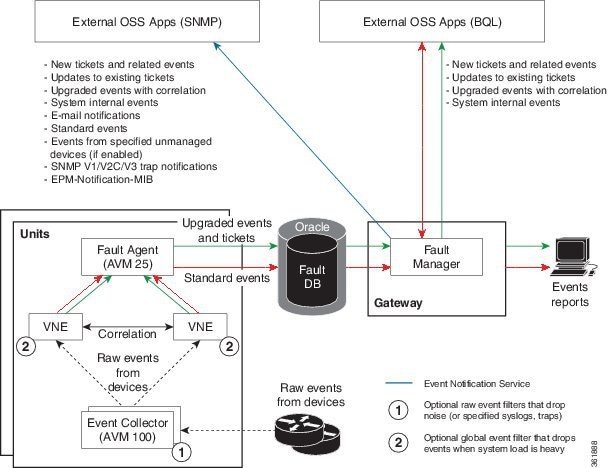
All upgraded and standard events are saved in the Oracle Fault Database, along with events from unmanaged devices (if notification from unmanaged devices is enabled; refer to the Cisco Prime Network Integration Developer Guide). The Oracle Fault Database schema name is the same as pnuser . For example, if pnuser is pn41 , the database schema is named pn41 . For more information on the database schemas in the Oracle database, see Overview of the Prime Network Oracle Database and Schemas.
Note The Event Archive (pnuser_ep schema) is no longer used in Prime Network (it is still created but is empty). Data that was saved in that schema is now saved in the Fault Database schema.
The following topics describe how the Event Collector, VNEs, and the Fault Agent (AVM 25) work together to process incoming notifications from devices. For more details about the event flow illustrated in Figure 9-1, refer to the Cisco Prime Network Integration Developer Guide.
Event Collector (AVM 100)
The Event Collector is the first receiver for incoming event notifications from devices. It is an internal service that is part of AVM 100. During installation, Event Collectors are created on the gateway and all units, but a single Event Collector AVM is started only on the gateway. By default, all new VNEs will register with the Event Collector on the gateway server. This Event Collector has the internal address 0.0.0.0 (this address is not related to the device IP address).
When an event, trap, or syslog is received by the Event Collector, the Event Collector does the following:
- Performs initial parsing to obtain basic information about each event.
- If a noise filter is enabled, drops the events. No event processing or archiving is performed, nor are the events forwarded to the Event Notification Service (ENS). You can configure a noise filter to:
– Drop ciscoConfigManEvent traps. See Filtering Out ”Pure Noise“ Traps Using the ciscoConfigManEvent Trap Filter.
– Drop traps or syslogs that you specify. For more information, contact Advanced Services.
– If saving events from unmanaged devices is enabled, forwards the events to AVM 25. (To enable saving these events, refer to the procedure in the Cisco Prime Network Integration Developer Guide.)
– If an Event Notification Service (ENS) for these events is configured and running, sends the events to the Event Notification Service. See Configuring Trap and E-Mail Notifications (Event Notification Service).
- Distributes each event to its corresponding VNEs. (The VNEs must be registered with the Event collector.).
The unit on which the Event Collector AVM is running must have a database connection. If it does not have a database connection, events from unmanaged devices and events from down VNEs (that are registered to that Event Collector) will not be saved to the Fault Database.
Event Collector and Unit Server High Availability
You can configure the Event Collector to run on a unit instead of the gateway. If the unit is also configured with unit server high availability, the Event Collector on the standby unit will drop all events until a switchover occurs.
The standby unit contains a port watchdog script that listens for events on the unit’s Syslog and SNMP ports. The script prevents unnecessary ICMP unreachable messages being sent back to the network. If a switchover occurs, the standby unit and Event Collector AVM will start, and the watchdog script releases the ports.
When the original unit comes back up, the standby Event Collector AVM goes back down, and the watchdog script recommences listening on the standby unit’s Syslog and SNMP ports.
Note If the Cisco Prime Performance Manager application is also installed (with Prime Central), the Prime Network Event Collector will receive threshold crossing alarm (TCA) events from Prime Performance Manager components and do the following:
- Save TCA events in the Oracle Fault Database.
- Forward TCA events to appropriate VNEs. The events are currently not parsed by the VNE. They will be identified as standard traps and will be dropped. If desired, you can forward them to an Event Notification Service (see Configuring Trap and E-Mail Notifications (Event Notification Service)).
No special configuration is required.
Prime Network also receives EPM-MIB traps from the network. By default Prime Network receives EPM-MIB traps from any source in the network. If desired, you can configure Prime Network to only process EPM-MIB traps arriving from a specific Prime Performance Manager server. For more information, contact Advanced Services.
VNEs
VNEs must be registered with an Event Collector’s internal address (this address is not related to the device IP address). When a VNE is first initialized, the following occurs:
- The VNE reads this Event Collector’s internal address from the registry. By default, all new VNEs will register with the Event Collector on the gateway server. This Event Collector has the internal address 0.0.0.0.
- The VNE registers its management IP address with this Event Collector.
If the Event Collector receives a trap or syslog, and the trap or syslog’s source IP address matches the VNE’s management IP address, the Event Collector will forward the syslogs or trap to that VNE.
A VNE may have more than one IP address registered with the Event Collector, (such as when a device is using other IP addresses as sources for syslogs or traps). These IP addresses can be discovered automatically from the device configuration but can also be manually configured using the VNE Event settings in Prime Network Administration (see VNE Properties: Events).
When a VNE receives an event from the Event Collector, the VNE does the following:
- If a Global Event Filter is configured and system load is high, the VNE drops any events that match the filter. By default, no filters are implemented. To configure a filter, see Configuring the AOP Global Event Filter.
- The VNE determines whether an event is an upgraded event or a standard event (see Upgraded Events and Standard Events). Standard events are sent to AVM 25 to be archived in the Oracle Fault Database; no further action is taken on those events.
- The VNE associates the event to its NE (for example, associating a port down to a device’s physical interface). If the NE is a physical interface, the VNE will check if alarms are disabled on the interface.
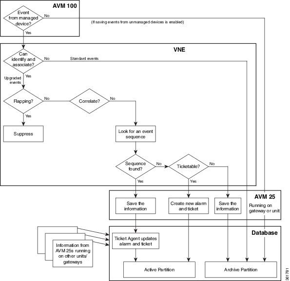
From this point, the VNE performs a variety of tasks depending on the configuration of the event. Figure 9-2 shows what the VNE does if correlation is enabled, while Figure 9-3 illustrates what the VNE does if correlation is not enabled.
Figure 9-2 Event Processing—Events With Correlation Enabled
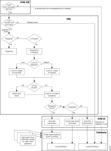
Figure 9-3 Event Processing—Events With No Correlation
AVM 25 (Fault Agent)
AVM 25 requires a database connection. If a direct connection is not available, you can configure AVM 25 without connectivity to forward its events to another AVM 25 that does have a database connection. This is called using a proxy AVM 25 . How to do so is described in Configuring a Proxy Database Connection for Units Not Connected to Database.
AVM 25 saves to the database all information it receives from a VNE. AVM 25 creates a new ticket when a VNE forwards a new alarm that is ticketable and for which a root cause was not found. The information is forwarded to the active partition in the Oracle Fault Database.
If an event is related to an existing ticket, AVM 25 forwards the information to the Ticket Agent in the Oracle Fault Database. The event is assigned the same ticket ID and alarm ID as the existing information in the database.
In some cases, the data that AVM 25 forwards is immediately archived (saved to an archive partition in the Fault Database). Events that are immediately archived are:
Configuring the Event Collector to Listen for Incoming Events
Although Event Collector AVMs are created on the gateway and all units during installation, the gateway Event Collector AVM is the only one that is started. You can configure an Event Collector to run on a unit instead, or configure multiple Event Collectors. These topics describe the supported scenarios and best practices:
- Setting Up the Event Collector: Supported Scenarios
- Enabling a Single Event Collector on a Gateway or a Unit
- Configuring and Enabling Multiple Event Collectors
- Registering VNEs with a Non-Default Event Collector
For an overview of how incoming events are handled, see How Prime Network Handles Incoming Events
Setting Up the Event Collector: Supported Scenarios
Note Deploying multiple Event Collectors does not increase the overall rate at which Prime Network parses, correlates, and saves information in the Fault Database. If Prime Network can parse and correlate 100 events per second, and you deploy two Event Collectors this number will not increase to 200.
The following guidelines can help you decide which Event Collector configuration is best for you:
- If event archiving is disabled, the Event Collector AVM does not require database connectivity.
- The Event Collector on a unit in standby mode will not forward any events to the Oracle database; it will drop all events.
- AVM 25 always requires database connectivity. If a connection is not available, you can configure AVM 25 to use a proxy AVM 25. (See Configuring a Proxy Database Connection for Units Not Connected to Database.)
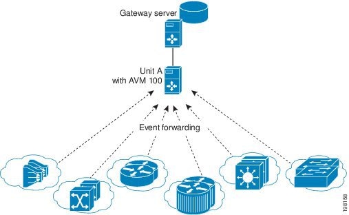
Example: Single Event Collector on Gateway Server
Figure 9-4 illustrates how events should be forwarded in a configuration where a single Event Collector is enabled on the gateway server.
Figure 9-4 Single Event Collector On Gateway Server
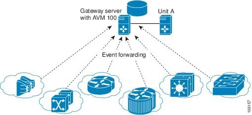
For this scenario, because the Event Collector AVM is enabled on the gateway server by default, all you must do is:
1. Configure the network elements to forward events to the gateway server.
2. Make sure all other Event Collectors are disabled. The Event Collector AVM is enabled on the gateway server by default. If you have to manually enable it, see Enabling the Event Collector on the Gateway Server.
This scenario would also apply to a gateway configured with gateway local redundancy. If the backup gateway came online, it would use the same IP address as the original gateway, so it would continue to receive events sent from network elements.
You could also use this scenario where a gateway is configured with gateway geographic redundancy. However, if the backup (remote) gateway came online, it would have a different IP address from the local gateway. Therefore, you should configure network elements to also forward events to the remote gateway as part of Step 1.
Example: Single Event Collector on Unit Server (No Unit High Availability)
Figure 9-5 illustrates how events should be forwarded in a configuration where one Event Collector is enabled on a unit server.
Figure 9-5 Single Event Collector On Unit Server
For this scenario, you must do the following:
1. If it is enabled, disable the Event Collector AVM on the gateway server (it is enabled on the gateway server by default).
2. Configure the network elements to forward events to the unit server that will host the enabled Event Collector.
3. Start the Event Collector AVM on the unit server and make sure all other Event Collectors are disabled. See Enabling a New Event Collector on a Unit.
4. If the unit with the running Event Collector does not have connectivity to the database, disable event archiving on the unit as described in Purging Configuration Archives and Software Images. (In addition, you should configure a proxy AVM 25 on this unit. See Configuring a Proxy Database Connection for Units Not Connected to Database.)
No other configuration changes are required. New VNEs will automatically register to this Event Collector.
If the unit with the enabled Event Collector fails and is not operational, you must do the following:
1. Repeat the previous steps on the new machine.
2. Move all AVMs to the new machine (see Moving and Deleting AVMs). When the moved VNEs start, they will automatically register to the new Event Collector.
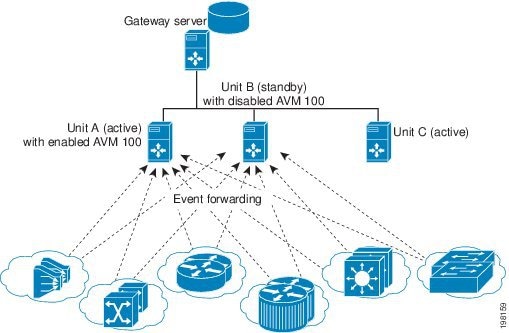
Example: Single Event Collector on Unit Server with Unit High Availability
Figure 9-6 illustrates how events should be forwarded in a configuration where one Event Collector is enabled on a unit server, and the unit server is part of a protection group that contains Unit A (an active unit with an enabled Event Collector), Unit B (standby unit with disabled Event Collector), and Unit C (active unit). See AVM 100 and Unit Server High Availability, for details about how the Event Collector operates in a unit server high availability scenario.
In Figure 9-6, devices are managed by Unit A.
Figure 9-6 Event Collector On Unit Server with Unit High Availability
For this scenario, you must do the following:
1. If it is enabled, disable the Event Collector AVM on the gateway (it is enabled on the gateway by default).
2. Configure and start the Event Collector AVM on the active unit as explained in Enabling a New Event Collector on a Unit. (The Event Collector AVM on the standby unit should not be enabled.)
3. Configure the network elements to forward events to both the active and standby units.
4. If any of the units with a running Event Collector do not have connectivity to the database, disable event archiving on them, and configure a proxy AVM 25 on this unit. See Configuring a Proxy Database Connection for Units Not Connected to Database.)
5. If the active unit has a connection to the database, the standby units should also have a connection to the database.
If the unit with the enabled Event Collector fails, the Event Collector on the standby unit is automatically started and the VNEs are automatically reregistered with the Event Collector on the standby unit. See AVM 100 and Unit Server High Availability for information on what happens if the failed unit comes back up.
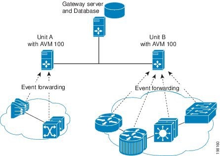
Example: Multiple Event Collectors on Unit Servers (No Unit High Availability)
Prime Network supports multiple enabled Event Collectors. The Event Collectors can be on the gateway and units, or just the units.
Figure 9-7 illustrates how events should be forwarded in a configuration with two Event Collectors enabled on different unit servers. This configuration is appropriate to a network in which devices have connectivity issues with the configured single Event Collector.
Deploying multiple Event Collectors does not increase the overall rate at which Prime Network parses, correlates, and saves information in the Oracle Fault Database. If Prime Network can parse and correlate 100 events per second, and you deploy two Event Collectors this number will not increase to 200.
Note This scenario can also increase SNMPv3 decryption capabilities. For information on this and other deployment information and recommendations, contact your Cisco representative.
Figure 9-7 Event Collector On Two Unit Servers with No Unit High Availability
For this scenario, you must do the following:
1. If it is enabled, disable the Event Collector AVM on the gateway (it is enabled on the gateway by default).
2. Configure and start the Event Collectors as explained in Enabling a New Event Collector on a Unit.
3. Configure the network elements to forward events to one of the units with an enabled Event Collectors.
4. If any units do not have connectivity to the database, disable event archiving and configure a proxy AVM 25 on those units. See Configuring a Proxy Database Connection for Units Not Connected to Database.
5. For the group of VNEs you want to use the newly defined Event Collector, you must manually register the VNEs with the new Event Collector. See Registering VNEs with a Non-Default Event Collector.
Enabling a Single Event Collector on a Gateway or a Unit
During installation, an Event Collector AVM is created on the gateway and all units, but it is started only on the gateway. By default, the enabled Event Collector has the internal address 0.0.0.0 (this address is not related to the device IP address). All new VNEs will register with the Event Collector on the gateway server.
Enabling the Event Collector on the Gateway Server
Although the Event Collector runs on the gateway by default, there may be instances where it has been stopped. If so and you need to restart it, use the following procedure.
- Configure the network elements to forward traps and syslogs to the gateway server that will contain the enabled Event Collector.
- Make sure all other Event Collectors are disabled.
If no other Event Collector was enabled after the gateway Event Collector was stopped, do the following to restart the Event Collector:
Step 1 In the All Servers branch, open the gateway branch.
Step 2 Right-click the Event Collector AVM (AVM 100) and choose Actions > Start .
If an Event Collector was enabled on another unit, do the following:
Note This procedure requires a gateway restart.
Step 1 Stop the Event Collector AVM on the unit.
Step 2 Stop the unit on which the Event Collector was enabled.
Step 3 Restart the gateway to apply your changes. See Stopping and Restarting Prime Network Components.
Step 4 Start the Event Collector AVM on the gateway.
The Event Collector will begin processing events when they are received. By default, any new VNEs will register with the Event Collector on the gateway server.
Enabling a New Event Collector on a Unit
Follow this procedure to start a single Event Collector on a unit.
Note If an Event Collector was previously enabled and is now disabled, the new Event Collector will automatically take the internal address 0.0.0.0. (This address is not related to the device IP address.)
- Configure the network elements to forward traps and syslogs to the unit that will contain the enabled Event Collector.
- If you are using unit server high availability, you must also configure the network elements to forward traps and syslogs to the standby unit.
- Make sure all other Event Collectors are disabled.
Note This procedure requires a gateway restart.
To enable the Event Collector on a unit:
Step 1 If an Event Collector was enabled at any time since the last boot, log in as pnuser and stop and restart the gateway server:
#
cd $ANAHOME/Main
#
networkctl restart
Step 2 In the Servers branch, open the unit branch.
Step 3 Right-click the Event Collector AVM and choose Actions > Start . The new Event Collector will automatically take the internal address 0.0.0.0.
By default, any new VNEs will register with the Event Collector on the unit.
Configuring and Enabling Multiple Event Collectors
Configuring a network to have two Event Collectors enabled on different unit servers is appropriate to a network in which devices have connectivity issues with the configured single Event Collector. However, deploying multiple Event Collectors does not increase the overall rate at which Prime Network parses, correlates, and saves information in the Oracle Fault Database. If Prime Network can parse and correlate 100 events per second, and you deploy two Event Collectors this number will not increase to 200.
An illustration of this configuration is provided in Example: Multiple Event Collectors on Unit Servers (No Unit High Availability).
Note This scenario can also increase SNMPv3 decryption capabilities. For information on this and other deployment information and recommendations, contact your Cisco representative.
To configure multiple Event Collectors you must edit the registry using the runRegTool.sh script.
The runRegTool.sh script is in the directory NETWORKHOME /Main and uses the following format:
runRegTool.sh -gs 127.0.0.1 set unit-IP “avm100/agents/da/ vne-key /trap/xidip” event-collector-address
The runRegTool.sh script accepts the following arguments:
Complete the following procedure for each additional Event Collector that needs to be configured. Because this is a completely new Event Collector, you do not have to stop or restart any AVMs.
Configure the network elements to forward traps and syslogs to the appropriate Event Collector. If you are using unit server high availability, traps and syslogs should be forwarded to both the active and standby units.
To configure multiple Event Collectors:
Step 1 From the gateway, issue the following runRegTool.sh script to add an additional Event Collector to Prime Network (run this command as pnuser ):
#
cd $ANAHOME/Main
#
./runRegTool.sh -gs 127.0.0.1 set
unit-IP
“
avm100/agents/trap/xidip”
unit-IP
The update is automatically propagated from the gateway to the relevant units.
Step 2 Start the Event Collector AVM on the unit with Prime Network Administration by right-clicking the AVM and choosing Actions > Start .
Step 3 If you want any existing VNEs to register with an Event Collector other than the default (at 0.0.0.0), perform the instructions in Registering VNEs with a Non-Default Event Collector.
When you add new VNEs, you must register the VNEs to the appropriate Event Collector as described in Registering VNEs with a Non-Default Event Collector.
Example Procedure for Configuring Two Event Collectors on Two Units
This example illustrates how to configure an Event Collector to run on one unit, and a second Event Collector to run on a second unit. The configuration is as follows:
– Contains AVM 100, which is an Event Collector with the address 192.168.10.2.
– Contains AVM 200, which is an AVM that contains user-created VNEs.
– Contains AVM 100, which is an Event Collector with the address 192.168.10.3.
– Contains AVM 300, which is an AVM that contains user-created VNEs.
In this example, two Event Collectors are configured, one on each unit. Each Event Collector handles the events (SNMP traps and syslogs) sent from the network elements that correspond to the VNEs it manages.
After installing the gateway and the two units, configure the Event Collectors and the VNEs:
Step 1 Log into the gateway as pnuser and change to the Main directory.
Step 2 Issue the following commands to configure the Event Collector addresses:
#
./runRegTool.sh -gs 127.0.0.1 set 192.168.10.2 “avm100/agents/trap/xidip” 192.168.10.2
#
./runRegTool.sh -gs 127.0.0.1 set 192.168.10.3 “avm100/agents/trap/xidip” 192.168.10.3
Step 3 Issue the following commands to configure the VNEs to register to their Event Collector ( vne-key is the VNE name):
a. For each VNE configured to receive traps and syslogs from the Event Collector (AVM 100) on Unit 1, use the following command (note the use of ip , not xidip ):
#
./runRegTool.sh -gs 127.0.0.1 set 192.168.10.2 “avm200/agents/da/vne-key/trap/ip” 192.168.10.2
b. For each VNE configured to receive traps and syslogs from the Event Collector (AVM 100) on Unit 2, use the following command:
#
./runRegTool.sh -gs 127.0.0.1 set 192.168.10.3 “avm300/agents/da/vne-key/trap/ip” 192.168.10.3
c. Restart the reconfigured VNEs by right-clicking each VNE and choosing Actions > Stop , and then Actions > Start .
Step 4 Start each new Event Collector with Prime Network Administration by right-clicking the Event Collector AVM and choosing Actions > Start .
Registering VNEs with a Non-Default Event Collector
If you do not want a VNE to be registered with the default Event Collector—that is, the Event Collector that uses the internal address 0.0.0.0—you must manually change the VNE registration. (This internal address is not related to the device IP address.)
Note Before performing the following procedure, verify that all VNEs are configured in the relevant units.
Complete the following procedure to register VNEs to an enabled Event Collector:
Step 1 Choose the Event Collector that is to receive the traps and syslogs for the VNE.
Step 2 Locate the AVM on which the VNE resides.
Step 3 Log into the gateway as pnuser , and change to the Main directory.
Step 4 Issue the following runRegTool.sh script ( vne-key is the VNE name):
# .
/runRegTool.sh -gs 127.0.0.1 set
unit-IP
“avm
xxx
/agents/da/
vne-key
/trap/ip”
unit-IP
The update is automatically propagated to the relevant units. For details on the command syntax, see Example Procedure for Configuring Two Event Collectors on Two Units.
Step 5 Reload the VNE with Prime Network Administration by right-clicking the VNE and choosing Actions > Start .
Configuring a Proxy Database Connection for Units Not Connected to Database
If a unit server does not have a direct connection to the database, you can configure another unit to be its proxy and persist event information to the Oracle Fault Database. But because there is no proxy support for the Event Collector (AVM 100), raw events will not be saved to the Fault Database and the log will contain error messages. Therefore, disable raw event archiving and then configure the proxy database connection by editing the avm25.xml registry file for the unit that does not have database connectivity. The proxy unit will process the events as part of its normal event flow.
Step 1 On the unit that has no database connections, make sure raw event archiving is disabled.
a. Choose Tools > Registry Controller > Database from the main menu of the Administration GUI client.
b. In the Archiving Raw Events field, choose false and click Apply .
c. Restart the Event Collector (AVM 100).
Step 2 On the unit that has no database connection, log in as pnuser and edit the registry to add the proxy instructions using the following runRegTool.sh scripts:
runRegTool.sh -gs 127.0.0.1 add unit-IP “avm25/services/management/proxy”
runRegTool.sh -gs 127.0.0.1 set unit-IP “avm25/services/management/proxy/IP” proxy-unit-IP
This runRegTool.sh scripts requires the following arguments:
The IP address of the unit server that does not have a database connection. |
|
The IP address of the unit server that has a database connection and will act as a proxy for the unit server at unit-IP . |
To configure Unit 1 to use Unit 2 as a proxy for AVM 25, enter these commands:
#
cd $ANAHOME/Main
#
./runRegTool.sh -gs 127.0.0.1 add 192.168.10.2 “avm25/services/management/proxy”
#
./runRegTool.sh -gs 127.0.0.1 set 192.168.10.2 “avm25/services/management/proxy/IP” 192.162.11.1
Configuring Trap and E-Mail Notifications (Event Notification Service)
Figure 9-1 illustrates how Prime Network processes incoming events. All events that are sent to the Fault Manager (which runs on the gateway) can be forwarded to external OSS applications using an Event Notification Service. Trap notifications can include additional information, such as an interface description or the business tag associated with an NE.
You can also use this service to configure e-mail notifications so that users are immediately informed about urgent events. A service can include network and non-network events, upgraded (actionable) and standard (non-actionable) events, and events from unmanaged devices. All events and tickets are normalized into the CISCO-EPM-NOTIFICATION-MIB trap format before they are forwarded.
Note If you want to include events from unmanaged devices, you must add the devices to the list of unmanaged devices sending notifications to the Event Collector (AVM 100); refer to the Cisco Prime Network Integration Developer Guide for instructions on how to do this.
This procedure explains how to create or edit an e-mail or trap notification service.
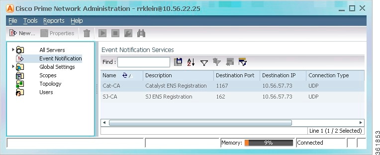
Step 1 Click Event Notification . If any services already exist, they are listed in the content area. The last column lists the total number of notifications that have been sent by each service. See Figure 9-8 for an example.
Figure 9-8 Event Notification Service Window Listing Existing Services
Step 2 Configure the service’s general characteristics and specify whether you want to forward the events as traps or by e-mail.
a. Enter the following basic information.
b. If you specified a trap notification service, provide the following trap information.
c. If you specified an e-mail notification service, provide the following e-mail information.
d. When you are done, click Next .
Step 3 Select the events and event information you want to include in (or exclude from) the trap or e-mail notification. For optimal performance, only include specific events in which you are interested (by clicking Select Types and specifying the events).
a. Specify the general categories of information you want to include in the trap or e-mail notification in the Notification Types area.
|
Updates made to the properties in which you are interested (by clicking Select Properties and choosing the properties) |
||
b. For Network and non-network events, specify the event types that you want to include in (or exclude from) the trap or e-mail notification.
|
Filters the events or tickets out of the trap or e-mail notification. When you choose an event, Prime Network will also exclude: |
||
|
(Network and Non-Network Events only) Select the events to include in the filter. You can select events at these levels:
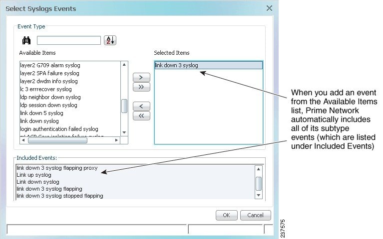
When you add events to the filter, Prime Network includes all clearing events To specify event types for the filter: 1. Choose the category: Network and/or non-network events. 2. Choose the type, such as Syslogs, Traps, Service events, System events, and so forth. 3. To choose specific events within the types, click Select Types . This opens a dialog box that lists all of the supported event types. When you choose an event type, its subtypes are displayed in the Included Events list. If you do not choose specific events, Prime Network will forward all events of that type. Figure 9-9 shows that when you select the link 3 down syslog (under Selected Items), Prime Network automatically includes all of its subtype events (which are listed under Included Events). |
||
Figure 9-9 Example: Event Type and Subtypes
c. Choose the event or ticket severities that you want to include in (or exclude from) the trap or e-mail notification and enter them in the Filter Events/Tickets by Severity area.
d. When you finish selecting the events, click Next .
Step 4 In the Source Selection dialog box, specify the source of the events to be included in (or excluded from) the service.
a. Select one of the following.
Note If you include an IP address for an unmanaged device, you must add the address to the list of unmanaged devices sending notifications to the Event Collector (AVM 100); refer to the Cisco Prime Network Integration Developer Guide for instructions on how to do this.
– For u nmanaged NEs or to choose all NEs , use Include all Sources . You can exclude devices in a later step.
– For managed NEs , choose I nclude managed network elements or Include specific IP address or managed network element. New VNEs will also be included. You can exclude devices in a later step.
Note The source for network events for topological links depends upon which devices are included in the notification service. If only one device is in the notification service, that device’s IP address is the source. If both devices are in the notification service, the A-side device IP address is the source (this is also the case for devices specified as 0.0.0.0). If neither device is included in the notification service, the link-related event is not forwarded.
For managed NEs , you can create a filter that will choose devices by device type. Check Include specific managed element types , and provide the NE information. You can use this choice alone or in conjunction with a choice from the previous step.
b. To exclude specific devices from the service, enter their IP address or choose them from a device list in the Exclude the following managed elements/IP addresses area.
c. When you finish specifying the sources, click Next .
Step 5 (Trap notifications only) Optionally, specify the additional data you want the notification to include by adding data to the Trap Display Options dialog box (shown in Figure 9-10). For example, you could include interface descriptions, business tags, ticket troubleshooting information, information included in the ticket, and so forth.
Figure 9-10 Display Options Page for Trap Notifications
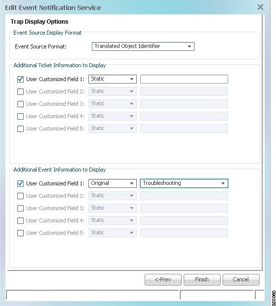
a. In the Event Source Display Format area, choose how you want to display the data retrieved from the NE.
b. In the Additional Ticket (or Event) Information to Display area, specify the data you want to add to the trap. Prime Network will populate the user customized fields in the trap with the data you specify. (For details on the exact fields that are used, refer to the Cisco Prime Network Integration Developer Guide .
For example, you could display the troubleshooting information for a ticket in the trap notification as shown in Figure 9-10:
– Choose Static in one of the user customized fields, and enter a link or location of an Events Troubleshooting Report that you previously generated.
– Choose Original > Element Type and the element type will be included in the notification.
– (For Cisco ASR 5000 traps, and Cisco ASR 5000 traps tickets whose root cause is a trap) Choose Original > Troubleshooting and the troubleshooting information will be included in the notification.
– Choose Translated > Initiating Trap and the initiating trap ID information with the translated value is included in the notification (in a standalone mode environment). This is applicable only for ticketable traps.
– Choose Translated > Initiating Trap , Details , Troubleshooting , and the translated value of troubleshooting information of the trap along with trap details of the Network Event Properties window and the initiating trap ID are included in the notification (in a suite mode environment). These three details are concatenated by a string (0Iti1D2T). The concatenation information can be viewed in any trap receiver configured to receive notification from Prime Network (in the suite mode environment). This is applicable only for ticketable traps.
Step 6 Click Finish to create the notification service. A status message is displayed and, if successful, the new service will appear in Prime Network Administration.
Disabling Ticket Management in the Prime Network Vision and Events Clients
To prevent synchronization problems for fault-related events and tickets, you can configure Prime Network to disallow ticket actions in the Vision and Events clients. When these operations are disallowed, users can only manage the ticket lifecycle through BQL or the external OSS. To disable ticket actions:
Step 1 Select Global Settings > Event Management Settings .
Step 2 In the Tickets area, check Disable ticket actions and click Apply .
Step 3 Restart the Vision and Events clients. You can terminate user sessions using the procedure in Managing Client and User Sessions.
Controlling the Vision Client Event Displays (Standard Events, History Size)
These topics describe some settings you can adjust from the Administration client to control what users see in the Vision client.
Adding Standard Events to the Latest Events Tab (Map Display)
Standard events are syslogs and traps that are not recognized by the Event Collector. They are immediately saved in the database as archived events, and no additional actions are taken on these events. Users can identify standard events by their archive setting, which will be set to true. By default, the only places where users can see standard events are:
- From the Events client under the Standard tab.
- From the Vision client under the Network Events tab (in a device inventory view).
The Vision client also has a Latest Events tab (in the map view) that displays incoming ticketable events (traps, syslogs, and Service events generated by Prime Network). By default, standard events are not displayed in the Latest Events tab. This is done to protect performance; normally there are 3 times as many standard events than upgraded events. If you do want standard events to be displayed in that tab, adjust the global settings as follows.
Step 1 Select Global Settings > Event Management Settings .
Step 2 In the Standard Events area, check Display standard events in Latest Events tab in Vision and click Apply .
Step 3 Restart the Vision client. You can terminate user sessions using the procedure in Managing Client and User Sessions.
Controlling When Events Are Removed From the Device Inventory Event Display
The inventory event display is launched when a user views a device’s inventory in Prime Network Vision, allowing users to see some of the events and tickets on devices within their scope. By default, network and provisioning events are removed from the display after 6 hours, and no more than 15,000 events are displayed. You can control the default settings for all Vision clients from the Administration global settings.
Users can also adjust this setting from their Vision client by choosing Tools > Options . Client-specific changes will override what you set here.
Step 1 Select Global Settings > Event Management Settings .
Step 2 In the Inventory Event Viewer area, adjust the Maximum history size (in hours) and click Apply .
Step 3 Restart the Vision client. You can terminate user sessions using the procedure in Managing Client and User Sessions.
Configuring System TCAs
To configure new threshold crossing alarms, use the Soft Properties feature. Soft Properties allows you to extend the supported properties for an NE, including monitoring selected properties and generating an alarm when these properties cross a user-defined threshold or violate a condition. Prime Network filters out irrelevant data, and sends only meaningful notifications.
For information on how to configure TCAs using Soft Properties, refer to the Cisco Prime Network 4.3.1 Customization Guide .
Tracking Events Related to Fault Monitoring
The following table provides ways you can get historical information on issues related to fault monitoring.
AVM and other appropriate log files (see Log Files Reference) Detailed System Events report ( Reports > Run Report > Events Reports > Detailed Non-Network Events > Detailed System Events ) |
 Feedback