Use Plug and Play to Deploy New Devices

About Plug and Play

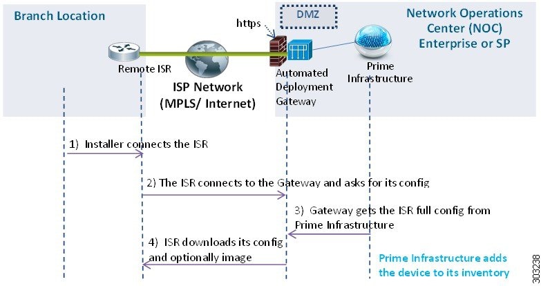
Cisco Prime Infrastructure helps automate the deployment of new devices on the network by obtaining and applying the necessary software image and configuration on a new network device. The Prime Infrastructure uses APIC-EM (Application Policy Infrastructure Controller) call-home and Cisco IOS auto-install (which uses DHCP and TFTP) features thus reducing the time a new device takes to join the network and become functional.

The Plug and Play feature of Prime Infrastructure uses the templates defined in Configuration > Templates > Features and Technologies that you can reuse and apply to new devices. You can streamline new device deployment by creating bootstrap templates, which define the necessary initial configurations to enable the device to communicate with Prime Infrastructure. You can specify (and predeploy ) software images and configurations that will be added to the devices in the future.

Prerequisites for Using Plug and Play

You must complete the following prerequisites.

  • Configure DHCP with the appropriate settings in the network as described in Sample DHCP Server Settings.
  • You must have an existing network connection (distribution/core) available in the branch or campus to where the new device is connecting.
  • The branch must have direct connectivity to the Cisco Prime Infrastructure server, or you must use the Plug and Play external server to connect to Cisco Prime Infrastructure.

Plug and Play Workflow

Cisco Prime Infrastructure allows you to perform an initial provisioning of a software image and configuration on a new device. To automate the deployment of a new device on your network, follow this workflow:

  1. Specify that Cisco Prime Infrastructure uses APIC-EM server for Plug and Play. See Integrate Map View With the Plug and Play Dashboard for information about setting up APIC-EM.
  2. Create a Plug and Play profile for your devices.The profiles are categorized as Routers, Switches, Wireless AP and Nexus Profiles. See Create Plug and Play Profiles That Define Device Deployments.
  3. Power on the device.
  4. Apply a bootstrap configuration to the device. The bootstrap configuration is a minimal configuration that is required for devices to establish a connection to the Cisco Prime Infrastructure gateway (APIC-EM). See Create a Bootstrap Configuration for Plug and Play.

In the case of Wireless AP profiles, the Primary, Secondary and Tertiary WLC details are required. See Create Wireless AP Plug and Play Profiles.


Note

In the case of Nexus devices, the Plug and Play workflow differs as these devices do not support bootstrap configuration. See Create Nexus Device Plug and Play Profiles for more details.


After you apply the initial configuration:

  1. The device communicates with the Cisco Prime Infrastructure server.
  2. Based on the Device Plug and Play ID / serial number, Cisco Prime Infrastructure verifies if this matches with the device ID in any of the Plug and Play preprovisioning definitions.
  3. If there is a match, Cisco Prime Infrastructure applies the upgraded software image and the configuration specified in the matched Plug and Play profile on the device.

    If there is no match for the device ID, Cisco Prime Infrastructure matches the device type with any of the existing type-based Plug and Play preprovisioning definitions.

  4. The device is added to its inventory and is managed by Cisco Prime Infrastructure.
  5. Plug and Play does not affect the inventory workflow. Cisco Prime Infrastructure applies the post Plug and Play configurations, if specified in the Plug and Play profile, on the device, only after the inventory is collected. See the chapter Add and Organize Devices.

After the bootstrap configuration is applied to the device, the installer connects the device to a WAN at the remote site. The device connects to the Plug and Play gateway using its serial number, and downloads the full configuration and (optional) Cisco IOS image (see the following image).

Figure 1. Plug and Play Branch Deployment


Note

The Automated Deployment Gateway is APIC-EM controller.


Use the Plug and Play Dashboard to Monitor New Device Deployments

Choose Configuration > Plug and Play > Dashboard and select the Home tab to view the dashboard of the Plug and Play application.


1

Click About to know about Plug and Play feature. See About Plug and Play.

2

Click Monitoring to view the details of devices in a map view. See Integrate Map View With the Plug and Play Dashboard.

3

Click Errors / Progress / Success to navigate to Device Status page. The details will be filtered and displayed accordingly.

4

Click to navigate to Device Status page to monitor the devices and its status.

5

Click to navigate to Bootstrap page to create bootstrap templates for profiles.

6

Click to navigate to Administration > Servers > APIC-EM Controller page.

7

Click to navigate to Plug and Play Profiles page to create profile for a device type.

8

Click to navigate to Profile Activation page to activate by providing values specific to device/type.

9

Click to navigate to Device Status page.

10

Click to navigate to Map View page to view the devices and their site locations.

11

Click to navigate to Plug and Play Profiles page.

12

Click to navigate to Administration > Dashboard > Jobs Dashboard page to view the job status.

Prerequisites for Using Plug and Play with APIC-EM

Cisco Prime Infrastructure supports APIC-EM GA Release 1.0, APIC-EM GA Release 1.1, APIC-EM GA Release 1.2, APIC-EM GA Release 1.3, APIC-EM GA Release 1.4 amd APIC-EM GA Release 2.0.


Note

Any APIC-EM configuration or settings must be done only in the Prime Infrastructure GUI and not in the APIC-EM.


You must preconfigure a profile which determines what is deployed on the devices (configurations, images, etc.). When the device calls home, based on the device’s serial number, the profile is matched and the device is provisioned with the same pre-configured image and configuration from Cisco Prime Infrastructure using APIC-EM's Plug and Play.

With APIC-EM Plug and Play integration, devices can be provisioned with http/https. If applicable, when the profile is created, you can also choose to install PKI (Public Key Infrastructure) and SUDI (Secure Unique Device Identifier) certificates on the device to use PKI and SUDI based authentication.

Prerequisites for Using Plug and Play with Nexus Devices

The following prerequisites should be met before connecting the Nexus device to the network:

  • A DHCP server to bootstrap the interface IP address, gateway address, script server (Cisco Prime Infrastructure 3.2) and script file (Plug and Play). See Configure DHCP Server.
  • A TFTP or HTTP server containing the configuration script used to automate the software image installation and configuration process. See Configure HTTP Server.
  • Cisco Prime Infrastructure 3. 2 server with created Plug and Play Nexus profile containing the software images and configuration files. See Create Nexus Device Plug and Play Profiles.
  • The Nexus device version must be higher than 6.2(12) or later to manage all the Nexus features in Cisco Prime Infrastructure.

Configure DHCP Server

The Nexus device sends out DHCP discover messages on all of the active interfaces (including the management interface) soliciting DHCP offers from the DHCP server or servers. The DHCP client on the Nexus device uses the device serial number or its MAC address in the client-identifier option to identify itself to the DHCP server. The DHCP server uses this identifier to send information, such as the IP address and script file name, back to the DHCP client.

The DHCP discover message also mandates the following options:

  • Option 66 (TFTP server name) or Option 150 (TFTP server address)—The DHCP server relays the TFTP server name or TFTP server address to the DHCP client. The DHCP client uses this information to contact the TFTP server to obtain the script file.
  • IP address
  • Default Gateway
  • Option 67 (Bootfile name)—The DHCP server relays the bootfile name to the DHCP client. The bootfile name includes the complete path to the bootfile on the TFTP server which is used by the DHCP client to download the script file.

Configure HTTP Server

Choose Administration > Settings > System Settings > General and select Server from the left navigation menu.

In the HTTP Forward section, select Enable to enable the device to contact the Plug and Play Gateway for downloading initial configuration and image. The default port is 80 but you can still change the port configuration on the device.


Note

Restart Cisco Prime Infrastructure for the changes to reflect.

Integrate APIC-EM Policy Information into Plug and Play

Prime Infrastructure communicates with APIC-EM via HTTPs and REST API’s exposed by APIC-EM.


Note

Prime Infrastructure requires a dedicated APIC-EM server. Hence you must not integrate the APIC-EM server with more than one Prime Infrastructure server to prevent data corruption and out of sync condition.


To integrate APIC-EM controller to Prime Infrastructure, follow these steps:

Procedure


Step 1

Choose Configuration > Plug and Play > Dashboard.

Step 2

In the Home tab, click on Server to view the Administration > Servers > APIC-EM Controller page.

Step 3

Click Add.

Step 4

Enter the APIC-EM controller IPv4 address.

Step 5

Enter the HTTPS port number to connect with APIC-EM.

Step 6

Enter your user name.

Step 7

Enter your password and confirm it.

The polling interval is not editable. The APIC-EM controller is polled periodically (every 5 minutes) to check the status of its connection / integration with Prime Infrastructure. The device status is also updated form the APIC-EM for every 5 minutes.

After the APIC-EM controller is added to Prime Infrastructure, you can view the reachability status of the APIC controller in same page. You can select a specific APIC-EM controller to view the history of the connection polling status. Make sure the APIC-EM connection is successful before using the service.

To navigate to Configuration > Plug and Play > Dashboard, click the link Please Click here to create Plug and Play Profiles.

The global option in Administration > Servers > APIC-EM Controller Global PnP/ZTD Settings is automatically set to APIC-EM when you add a valid APIC-EM controller into Prime Infrastructure.

The APIC-EM integration is not bi-directional, hence you should not make any changes in the APIC-EM for integration.


APIC-EM Site Sync

Prime Infrastructure can integrate and synchronize its inventory with APIC-EM. You need to have a dedicated instance of Prime Infrastructure that integrates with APIC-EM. The dedicated Prime Infrastructure instance can be used for monitoring the network only, not for provisioning.

From the dedicated instance of Prime Infrastructure, specify the APIC-EM instance from the Administration > Servers > APIC-EM Controller page. This Prime Infrastructure instance periodically syncs the sites, devices, device and location groups, WAN interface port groups, and endpoint associations with the APIC-EM instance. Prime Infrastructure collects inventory and other monitoring information for the synced devices and creates a new folder under All Devices > Location and adds the devices to the corresponding sites. Prime Infrastructure monitors the devices by collecting assurance and syslog information.

By default, Prime Infrastructure runs an APIC-EM integration sync job every six hours. If you remove sites and devices from APIC-EM, they are also deleted from Prime Infrastructure. If devices are added or updated in APIC-EM, Prime Infrastructure will also add and update them.

Create Plug and Play Profiles That Define Device Deployments

Choose Configuration > Plug and Play > Dashboardand in the Home tab, click PnP Profiles. The detailed summary of the list of plug and play profiles are displayed.

Cisco Prime Infrastructurehelps you create a Plug and Play Profile that allows any newly connected device to “call home” to the Cisco Prime Infrastructure server so that the device can be discovered, added to the inventory, and configured. This profile, also known as a Bootstrap Profile, places credentials on the device, eliminating the need to “console” into every device to setup before the device can be managed by Cisco Prime Infrastructure.

You can create any of the following Plug and Play profiles under the specific folders:

Depending on the type, you can create Plug and Play profiles that contain:

  • Software images only.

  • Configurations only.

  • Both software images and configurations.

  • PKI certificates and SUDI certificates.

  • Primary and Secondary Controllers, AP and Flexconnect groups (For Wireless AP only).

The profile can include additional post Plug and Play configurations (optional), that can be applied on the device only after the device is managed by Cisco Prime Infrastructure.


Note

You cannot create a profile under the root Plug and Play folder. Depending on the profile-type, you can create profiles only under the specific folders - Nexus Profiles, Switch Profiles, Router Profiles and Wireless AP Profiles.

Note

  • PnP scale supports any number of devices distributed across profiles, but a profile can support maximum of 500 devices per profile instance. If you want to increase this scale, create additional profile and add devices to the new profile.

  • A maximum of 50 devices will be provisioned simultaneously irrespective of the profile. The PnP agent will pick next set of devices after provisioning of the current 50 devices.

  • Cisco Prime Infrastructure stores details of the virtual domains under which profiles and profile instances are created and updated. The provisioned devices will be added to the inventory under the respective virtual domains and ROOT-DOMAIN.

  • Ensure that the management IP address is unique for each profile instance.

  • Adding location groups to profile instances while bulk importing or exporting of device profiles, is not supported. You can create rules under corresponding location groups to dynamically add the managed devices.


Create Router and Switch Plug and Play Profiles

A Plug and Play profile must have at least one of the following:

Procedure


Step 1

Choose Configuration > Plug and Play > Dashboardand in the Home tab, click PnP Profiles.

Step 2

Select the required profile (Router Profiles or Switch Profiles) from the left navigation pane, then click Add to view the details in Profile Summary tab.

Step 3

Provide the required information in the Profile Basic section.

You can select the required credential profile from theCredential Profile drop-down list to associate the credentials common to the device.

Step 4

(Optional) In the Profile Detail section, check the Enable Terminal Server check box to provision devices with terminal server IP and port.

Step 5

(Optional) In the Profile Detail section, check the Enable PKI check box to provision devices with PKI certificates. PKI certificates are installed on the device after the Image provision and configuration are complete. See Cisco Open Plug-n-Play Agent Configuration Guide, Cisco IOS XE Release 3E for more information.

If the Enable PKII check box is unchecked, the device is not provisioned with PKI certificates.

Note 
Enable PKI check box will be disabled for Switch Profiles.
Step 6

(Optional) In the Profile Detail section, check the Enable SUDI check box to provision devices with SUDI certificates. By enabling this option, you can specify that the APIC-EM controller must validate the SUDI certificate to authenticate the device.

Note 
If you select Enable SUDI, ensure that the device supports SUDI and add the device using the SUDI serial number.una
Step 7

From the Bootstrap Template drop-down list, select the bootstrap templates. You can also create a customized bootstrap template which will be saved in PnP Bootstrap Templates (User Defined). See Create a Bootstrap Configuration for Plug and Play.

Step 8

(Optional) From the Software Image drop-down list, select the required software images. This step is required only if you want to provision the device with images. See Import Software Images for Plug and Play Profiles.

Step 9

(Optional) From the Configuration Template drop-down list, select a previously created configuration template.

Step 10

(Optional) From the Post PnP Configuration Template drop-down list, select the required configuration template. This configuration is applied on the device once it is managed by Prime Infrastructure.

Step 11

Click Save as New Plug and Play Profile.

Step 12

The profile is created and the details in Profile Summary tab is displayed. You can edit the details and click Save to save the details in the same profile and click Save as New to create a new profile.

Step 13

Click Profile Instances tab.

Step 14

Click Add to add details for the devices for which you want to pre-provision the Plug and Play Profile. See Add Device Profiles into Router and Switches Plug and Play Profiles.


Import Software Images for Plug and Play Profiles

You can import a software image to include it as part of a Plug and Play profile.

Procedure

Step 1

Choose Inventory > Device Management Software > Software Images.

Step 2

Click Import, then specify the source from which the software image is to be imported.

Step 3

Specify the collection options and when to import the image file. You can run the job immediately or schedule it to run at a later time.

The image import job will run only once.

Step 4

Click Submit.

Step 5

To view the details of image management job, choose Administration > Dashboard > Jobs Dashboard.


Create Wireless AP Plug and Play Profiles

You can create a plug and play profile for a wireless AP to provision thousands of devices at a time.

Procedure


Step 1

Choose Configuration > Plug and Play > Dashboard, and in the Home tab, click PnP Profiles.

Step 2

Select Wireless AP Profiles from the left navigation pane and click Add to view the details in the Profile Summary tab.

Step 3

Provide the required information in the Profile Basic section.

In the Device Type field, Autonomous AP is auto-populated and is non-editable. It is mandatory to provide the PID value for Wireless AP profiles.

Step 4

Provide the required information in the Profile Detail section.

Step 5

Click Save as New Plug and Play Profile.

Step 6

The profile is created and the details in Profile Summary tab is displayed. You can edit the details and click Save to save the details in the same profile and click Save as New to create a new profile.

Step 7

Click Profile Instances tab.

Step 8

Click Add to add details for the devices for which you want to pre-provision the Plug and Play Profile. See Add Device Profiles into Wireless AP Plug and Play Profiles.


Create Nexus Device Plug and Play Profiles

To create a Plug and Play profile for Nexus devices, follow these steps:

Procedure


Step 1

Choose Configuration > Plug and Play > Dashboard and in the Home tab, click PnP Profiles.

Step 2

Select Nexus Profiles from the left navigation pane and click Add to view the details in the Profile Summary tab.

Step 3

Provide the required information in the Profile Basic section.

Select the required credential profile from the Credential Profile drop-down list to associate the credentials common to the device. See Apply Device Credentials Consistently Using Credential Profiles.

Step 4

From the System Image and Kick Start Image drop-down lists, select the required software images. See Import Software Images for Plug and Play Profiles.

Note 
While downloading from Cisco.com, ensure that both system and kick start images have the same image version.
Step 5

From the Configuration Template drop-down list, select either the system-defined Nexus POAP Configuration Template or a previously created configuration template and make additional changes.

Step 6

Click Save as New Plug and Play Profile.

Step 7

The profile is created and the details in Profile Summary tab is displayed. You can edit the details and click Save to save the details in the same profile and click Save as New to create a new profile.

Step 8

Click Profile Instances tab.

Step 9

Click Add to add details for the devices for which you want to pre-provision the Plug and Play Profile. See Add Device Profiles into Nexus Plug and Play Profiles.


Create Mobility Express WLC Plug and Play Profiles

To create a Plug and Play profile for Mobility Express WLC devices, follow these steps:

Before you begin

Ensure that the APIC-EM is synchronized with Prime Infrastructure.

Procedure


Step 1

Choose Configuration > Plug and Play > Dashboard and in the Home tab, click PnP Profiles.

Step 2

Select Mobility Express WLC Profiles from the left navigation pane and click Add to view the details in the Profile Summary tab.

Step 3

Provide the required information in the Profile Basic section.

(Optional) Select the required credential profile from the Credential Profile drop-down list to associate the credentials common to the device.

Step 4

From the Configuration Template drop-down list, select either the Mobility Express Day Zero Configuration Template.

If you want to import a raw configuration, do not select any configuration template. See Step 3 of Add Device Profiles into Mobility Express WLC Plug and Play Profile Instances.

Step 5

(Optional) In the Post Plug and Play Wireless Configuration Groups area, select the additional configuration to be pushed to the device after the device is managed by Prime Infrastructure, from the Wireless Configuration group drop-down list.

Step 6

(Optional) From the Software Image drop-down list, choose the required software images.

Note 

If you want to deploy the upgraded version of the software image, import the upgraded software image in the Inventory > Device Management > Software Images page. See Add (Import) Software Images to the Repository for more information.

Step 7

Click Save as New Plug and Play Profile.

Step 8

The profile is created and the details in Profile Summary tab is displayed. You can edit the details and click Save to save the details in the same profile and click Save as New to create a new profile.

Step 9

Click Profile Instances tab.

Step 10

Click Add to add details for the devices for which you want to pre-provision the Plug and Play Profile. See Add Device Profiles into Mobility Express WLC Plug and Play Profile Instances for more information.


Associate Devices with Plug and Play Profiles

You can pre-provision a device on any defined profile, and activate by providing values specific to device/type. To add devices in bulk, see Export, Edit and Import Device Profiles into Plug and Play Profiles.

You can perform either one of the following:

Alternatively, you can choose Configuration > Plun and Play > Dashboard, in the Home tab, click PnP Profiles to create a new Plug and Play profile. After creating the required Plug and Play profile, click Add in the Profile Instances tab to add device profiles.

Create New Plug and Play Profiles and Add Device Profiles

Procedure


Step 1

Choose Configuration > Plug and Play > Dashboard and in the Home tab, click Profile Activation.

Step 2

In the Select PnP Profile page, select Add device by creating new Profile.

Step 3

Select the type of profile you want to create from the Profile Type drop-down list.

Step 4

Enter the required information in the Profile Basic and Profile Detail sections. See Create Plug and Play Profiles That Define Device Deployments for information on profile creation.

Step 5

(Optional) Enter the Terminal Server IP and Port if the Enable Terminal Server check box has been selected while creating a Plug and Play profile.

Step 6

Click the arrow icon in the right to navigate to the Plug and Play Profile page to add device profiles to the created plug and play profile.

Step 7

(Optional) If the Enable Terminal Server check box is checked, import the raw configuration on the device by:

  1. Import the zip files or tar files which contains multiple text files. Each text file will contain raw configuration that needs to be applied to the device. You can also import a single text file if required.

    The name of the text file should be DeviceSerialID.txt or DeviceName.txt. For example if the device ID is FGLABCD443f, the text file containing the configuration details must be FGLABCD443f.txt or if the device name is XaaaXX, the text file containing the configuration details must be XaaaXX.txt.

  2. A job will be triggered for processing these files and uploading to APIC when the files are uploaded successfully.
  3. Verify the configuration has been successfully applied to the corresponding devices in that profiles by going to that particular profile in APIC.

Add Device Profiles to an Existing Plug and Play Profile

Procedure


Step 1

Choose Configuration > Plug and Play > Dashboard and in the Home tab, click Profile Activation.

Step 2

In the Select PnP Profile page, select Add device to an existing profile.

Step 3

Select the required profile from the Select Profile drop-down list, for which you need to add device profiles. See Create Plug and Play Profiles That Define Device Deploymentsfor information on profile creation.

Step 4

The details of the profile you selected gets auto-populated and are non-editable.

Step 5

Click the arrow icon in the right to navigate to the Plug and Play Profile page to add device profiles to the created plug and play profile.


Add Device Profiles into Router and Switches Plug and Play Profiles

To add a device profile to the required Plug and Play profile, follow these steps:

Procedure


Step 1

In the Plug and Play Device Provisioning Profile page, provide the required information.

  • Select the site location to which the device will be mapped from the Location drop-down list. This detail will be displayed in the Map View.
Note 
Before you add a device to a specific location, create a location group in Inventory > Device Management > Network Devices or Inventory > Group Management > Network Device Groups. See Create Location Groups.
Step 2

Click the arrow icon in the right to navigate to the Bootstrap Selection page.

Step 3

In the Bootstrap Selection page, the bootstrap template you selected in the profile creation phase will get auto-populated. You can edit the values as required.

  • Plug and Play Gateway Location—By default, the Prime Infrastructure server acts as the Plug and Play gateway server. You can modify the server by providing the external Plug and Play gateway IP address.

Click CLI to view the CLI summary of the bootstrap configured.

Step 4

Click the arrow icon in the right to navigate to the next pages.

Note 
If you had selected Software Image and Configuration Template in the profile creation phase, the Software Image, Configurationu and Post PnP Configuration tabs will be displayed in the Profile Activation page.
Step 5

(Optional) In the Software Image page, provide the required information.

Step 6

(Optional) In the Configurationu page, the configuration template you selected in the profile creation phase will be auto-populated. Provide the required information and navigate to the next page.

Click CLIto view the CLI summary.

Step 7

(Optional) In the Post PnP Configuration page, the configuration template you selected in the profile creation phase will be auto-populated. Provide the required information and navigate to the next page.

Click CLI to view the CLI summary.

Step 8

In the Management Credentials page, provide the required information. These device parameters ill be applied on the devices on provisioning.

Note 
If the device type is a router or switch, then in the Management Credentials page, the credential profile you selected in the profile creation phase will be auto-populated and the values cannot be edited.
Step 9

In the Profile Activation Summary page, the device details with their configurations is displayed.

Step 10

Click Finish to provision the device profile.

On successful provisioning, the device profile will be displayed in the Profile Instances page of the specific profile. Alternatively, the provisioning status of the device can be viewed at the Device Status page.

After the device is provisioned successfully, the device is added to the Prime Infrastructure inventory so that the device can be managed. The device is added to the Prime Infrastructure inventory based on the management parameters provided in the Plug and Play Profile. After the device is added successfully to the inventory, additional post Plug and Play configurations (if applicable) are applied on the device.

If there is a mismatch in credentials, the device is added to the inventory, but it will not have “Managed” status.


Export, Edit and Import Device Profiles into Plug and Play Profiles

You can perform import and export operations on device profiles in bulk. Instead of adding devices and specifying their attributes one at a time, you can import a CSV file that includes all the devices and their attributes. By performing bulk import, you can update the existing profiles and add new profiles. To update more than one device profile at a time, you can perform bulk export.

Procedure


Step 1

Choose Configuration > Plug and Play > Dashboard and in the Home tab, click PnP Profiles.

Step 2

Select the required Plug and Play profile from the left navigation menu. The details in Profile Summary tab is displayed.

Step 3

Click Profile Instances tab.

Step 4

Select the device profiles check-boxes you need to edit and click Export.

The CSV file with the device properties will be exported.The exported CSV file will not have the configuration information.. You can add devices or edit the properties of the existing devices in the spreadsheet. Do not change the attribute names while editing the spreadsheet.

For Mobility Express WLC profiles, you can enter either the serial number or MAC adress of the device.

Note 
If you want to export a blank CSV file, click Export without selecting any device profiles. A blank csv file will be exported even if there are no device profiles in the Profile Instances page.
Step 5

Click Import and choose the CSV file in which you entered the device details. Click Upload.

The CSV file is uploaded and a link to Administration > Dashboard > Jobs Dashboard is displayed.

Step 6

In the Jobs Dashboard page, click PnP Bulk Import from the left navigation menu to view the job status of the bulk imported file.


Deployment Based on Device Type

To deploy a Plug and Play profile based on the device type, you do not have to associate the device ID with the deployment profile. Device type-based deployment is useful primarily for switches that use the same set of images and configurations. Matching profiles are identified by the device type (PID) of the incoming device that is specified in the profile during the design phase.

During device type-based deployment:

  1. The device type is matched hierarchically; Cisco Prime Infrastructure searches for a profile with the same device type as that of the incoming device. If the profile does not match the device type, Cisco Prime Infrastructure searches for a profile that is defined for a higher level of the device type in the hierarchy. For example:
    • If the ‘switch_profile’ in Cisco Prime Infrastructure is defined for ‘Switches and Hubs’ and the incoming device is of type Switches and Hubs > Catalyst 2928 Series Switches > Catalyst 2928-24TC-C switch, and
    • If there is no profile defined specifically for this switch (Catalyst 2928-24TC-C or Catalyst 2928 Series Switches), then the ‘switch_profile’ is considered for deployment
  2. If Cisco Prime Infrastructure has multiple matching deployment profiles for a given device type, then Cisco Prime Infrastructure chooses the deployment profile that is created or has been recently updated.

Add Device Profiles into Wireless AP Plug and Play Profiles

Cisco Prime Infrastructure supports only APIC-EM for Wireless AP profiles. You must preconfigure a plug and play profile which determines the primary, secondary and tertiary WLC details that is required to be provisioned on the devices. See Create Wireless AP Plug and Play Profiles.

When the AP (Access Point) is connected to a network, the AP contacts the DHCP of the network to know the APIC-EM details. The AP then contacts the APIC-EM and based on the device’s serial number and PID, the profile is matched. AP contacts WLC which then pushes the image and configurations to the device.

To add a device profile to the required Plug and Play profile, follow these steps:

Procedure


Step 1

In the Plug and Play Device Provisioning Profile page, provide the required information.

Select the site location to which the device will be mapped from the Location drop-down list. This detail will be displayed in the Map View.

Note 
Before you add a device to a specific location, create a location group in Inventory > Device Management > Network Devices or Inventory > Group Management > Network Device Groups. See Create Location Groups.
Step 2

In the Profile Activation Summary page, the device details with their configurations is displayed.

Step 3

Click Finish to provision the device profile.

On successful provisioning, the device profile will be displayed in the Profile Instances page of the specific profile. Alternatively, the provisioning status of the device can be viewed at the Device Status page.


Add Device Profiles into Nexus Plug and Play Profiles

Before you begin, there is a set of prerequisites to be met. See Prerequisites for Using Plug and Play with Nexus Devices.

When a Nexus device is connected to the network, it follows the below workflow:

  1. Locates the configured DHCP server and establishes communication to get the IP Address, gateway, script server (Prime Infrastructure 3.2) and the script file (Nexus Plug and Play profile).
  2. The device then communicates with the Prime Infrastructure and downloads the created Plug and Play profile for Nexus device. See Create Nexus Device Plug and Play Profiles.
  3. The device then obtains the IP address of a TFTP server or URL of an HTTP server from which it downloads the image and the necessary configuration files.

To add a device profile to the required Plug and Play profile, follow these steps:

Procedure


Step 1

In the Plug and Play Device Provisioning Profile page, provide the required information.

Select the site location to which the device will be mapped from the Location drop-down list. This detail will be displayed in the Map View.

Note 
Before you add a device to a specific location, create a location group in Inventory > Device Management > Network Devices or Inventory > Group Management > Network Device Groups. See Create Location Groups.
Step 2

Click the arrow icon in the right to navigate to the Image Selection page.

The selected system and kick start images are auto-populated and cannot be edited.

Step 3

Click the arrow icon in the right to navigate to the Configuration page.

The configuration template you selected in the profile creation phase will be auto-populated. You should provide the Management Interface IP Address, Management Route IP Address and the other required information. This management IP address is configured to enable d to reach the Nexus device.

Click CLI to view the CLI summary.

Step 4

Click the arrow icon in the right to navigate to the Management Credentials page.

For Nexus devices, it is mandatory to specify the Management IP Address so that the device can be managed. Provide the other required information and navigate to the next page. These device parameters will be applied on the devices on provisioning.

Step 5

In the Profile Activation Summary page, the device details with their configurations is displayed.

Step 6

Click Finish to provision the device profile.


On successful provisioning, the device profile will be displayed in the Profile Instances page of the specific profile. Alternatively, the provisioning status of the device can be viewed at the Device Status page. The device is added to the Prime Infrastructure inventory so that the device can be managed.

Add Device Profiles into Mobility Express WLC Plug and Play Profile Instances

You can go to the Profile Activation page, by clicking the Add icon in the Profile Instances tab in the Mobility Express (ME) WLC Plug and Play Profiles page.

ME AP device should get the IP address from the DHCP server. Management IP should be different from the configured IP address on the ME AP. Both DHCP IP and Management IP should be in the same subnet.

Procedure


Step 1

In the Profile Activation page, provide the required information in the Plug and Play Device Provisioning Profile tab.

Step 2

Click the Configuration tab.

The configuration template you selected in the profile creation phase will be auto-populated. You should provide the Interface IP Address and the other required information.

If you had selected the Mobility Express Day Zero Configuration Template while creating the profile, it helps to convert the ME AP into ME WLC.

Click CLI to view the CLI summary.

Note 

This Configuration tab will not appear if you have not selected any Configuration Template while creating the profile. If you want to import raw configuration on the device, click Import Raw Config under the Profile Instances tab and import the configuration file from your local system. You can import the raw configuration after creating one profile instance. Ensure that name of raw configuration file is the same as the Serial Number or the Base Ethernet MAC address of the device. If you are providing the MAC address as the name of the file, make sure to provide the symbol "-" instead of ":".

Step 3

Click the Management Credentials tab.

The Management IP Address gets auto populated from Configuration tab if you have selected preloaded configuration file and you will not be able to edit it, else you must provide the Management IP Address so that the device will get added to the Prime Infrastructure inventory. Provide the SNMP and CLI parameters. These parameters will be added as additional commands to be pushed on the devices.

Step 4

In the Profile Activation Summary page, the device details with their configurations is displayed.

Step 5

Click Finish to provision the device profile.


On successful provisioning, the device profile will be displayed in the Profile Instances page of the specific profile. Alternatively, the provisioning status of the device can be viewed at the Device Status page. You can click the info icon next to the Post PNP Status to know the image upgradation status. The device is added to the Prime Infrastructure inventory so that the device can be managed. Once the Mobility Express WLC goes to the managed state, all the APs connected to the WLC will be added to the inventory. The image upgradation will start after the device goes to managed state.

The System job "Post PnP Image Upgrade" under "Infrastructure" runs on demand from Post PnP configuration for Mobility Express Controllers to perform Software Image Distribution and Activation. Once Mobility Express controller inventory collection is completed, this job will get triggered only if applicable. You can check image upgrade status for each devices under the job details.

Supported Devices and Software Images for Plug and Play

If you are using APIC-EM, the Prime Infrastructure Plug and Play will support only the devices supported by APIC-EM.

Refer Release Notes for Cisco Network Plug and Play to know the devices and the corresponding software images supported for APIC-EM.

For more Details on all the supported devices and the corresponding sysObjectIDs, see Cisco Prime Infrastructure Supported Devices.

Prerequisites for Deploying Bootstrap Configuration into a Device

To deploy bootstrap configuration into a device in a Cisco Prime Infrastructure Server:

  • Enable Cipher in Admin mode of the server by entering the following command.

ncs run pnp-ciphers enable

  • Click Enable in the HTTP Forward section of the Administration > Settings > System Settings page.
  • If you are going to use email to deliver either the bootstrap configuration or the PIN, you must have previously configured the mail server settings under Administration > Settings > System Settings > Mail Server Configuration.
  • Ensure TFTP is enabled on the Cisco Prime Infrastructure server by choosing Administration > Settings > System Settings > Server, then clicking Enable under TFTP. TFTP is enabled by default.

Create a Bootstrap Configuration for Plug and Play

A bootstrap configuration is a minimal configuration that is required for devices to establish a connection to the Prime Infrastructure gateway (APIC-EM). Prime Infrastructure provides a standard bootstrap configuration that you can use.

If you are using the DHCP option, you do not need to create a bootstrap configuration. See Export Bootstrap Configurations Using DHCP.

To create a user-defined bootstrap template, follow these steps:

Procedure


Step 1

Choose Configuration > Plug and Play > Dashboard and in the Home tab, click Bootstrap.

By default, an APIC Bootstrap and Plug and Play Bootstrap template will be displayed. These templates cannot be deleted.

Step 2

Select the specific Bootstrap check-box and click Clone to clone a similar template. This new template will be displayed as APIC Bootstrap_1, APIC Bootstrap_1_1, and so on or Plug and Play Bootstrap_1, Plug and Play Bootstrap_1_1 and so on, depending on the bootstrap you cloned.

Note 
  • You can rename the cloned template. Once renamed, you cannot change the template name again.
  • Make sure that you do not use the Configuration > Templates > Features & Technologies > CLI Templates > System Templates-CLI > Plug And Play Bootstrap to create a customized bootstrap template.

Step 3

Click Save.

Step 4

Click the pointer beside the Bootstrap template to view or edit the details.

Step 5

Click Update to save the changes. Click CLI to view the CLI summary.

Step 6

To delete any bootstrap template, select the specific bootstrap template check-box and click Delete.

These templates that you create will be saved in PnP Bootstrap Templates (User Defined).

You can choose this newly created bootstrap template when adding a profile instance by selecting the specific bootstrap template from PnP Bootstrap Templates (User Defined). The details will automatically be displayed and will be editable.

The bootstrap configurations that Prime Infrastructure provides the following content:

  • APIC-EM HTTP Bootstrap

    
    pnp profile network-pnp
    transport http ipv4 <APIC-EM server IP>
    
  • APIC-EM HTTPS Bootstrap

    
    crypto ca trustpoint <APIC-EM Server IP>.cisco.com
    enrollment mode ra
    enrollment terminal
    usage ssl-client
    exit
    crypto ca authenticate <APIC-EM Server IP>.cisco.com
    -----BEGIN CERTIFICATE-----
    Certificate detail
    -----END CERTIFICATE-----
    pnp profile network-pnp
    transport https ipv4 <APIC-EM Server IP> port 443
    !
    

How to Install Bootstrap Configurations?

A bootstrap configuration is a minimal configuration that is required for devices to establish a connection to the Cisco Prime Infrastructure gateway (APIC-EM). The bootstrap configuration can be installed on the devices using any of the bootstrap delivery methods that Cisco Prime Infrastructure supports:

  • Export and download the bootstrap—If you have access to the device console, you can export the bootstrap, and then copy and paste the bootstrap configuration to the device. See Export .
  • Deploying bootstrap configuration through terminal server. See Deploy the Bootstrap Configurations Using Terrminal Server in related topics.
  • Export and save the bootstrap to a USB flash drive—You can save the bootstrap configuration to a USB drive with the file name ciscortr.cfg. Connect the USB drive to the device, and then boot the device. The device will retrieve the bootstrap configuration from the USB drive. See Export Boostrap Configurations Using TFTP in related topics.
  • Email the bootstrap. See Email Bootstrap Configuration in related topics..
  • DHCP options based on the server you specified. See Export Bootstrap Configurations Using DHCP in related topics..
    • You can configure DHCP option 43 on the APIC-EM server IP under DHCP Configuration. When a device gets its IP address from DHCP, it will get the bootstrap configuration also.
  • Mobile application—You can use the Cisco Network Plug and Play mobile application.

Export the Bootstrap Configuration

You can export a bootstrap configuration and then manually apply the bootstrap on the device. After the bootstrap configuration is applied, the Plug and Play deployment is initiated and the administrator can view the configuration status on Prime Infrastructure.

Procedure


Step 1

Choose Configuration > Plug and Play > Dashboard, and in the Home tab, click PnP Profiles.

Step 2

From the Plug and Play Profiles page, select a profile from the list.

Step 3

Click Profile Instances.

Step 4

Click Export Bootstrap > Download Bootstrap, then click OKs.

Step 5

After the bootstrap configuration is downloaded and applied, the Plug and Play deployment is initiated.


Deploy the Bootstrap Configuration Using Terminal Server

If you have enabled the check box Enable Terminal Server while creating a Plug and Play profile you can deploy bootstrap config:

Procedure


Step 1

Select the devices from the Plug and Play profile.

Step 2

Click Deploy button.

Step 3

Click OK in the pop up dialogue box to trigger a job to execute the bootstrap on to the device directly by using Terminal Server.

You can check the status of the PnP Terminal Server job on the Job Dashboard.

The APIC will provision the device when the job is executed successfully. The device will be added to the Prime Infrastructure inventory once the device is provisioned.


Export the Bootstrap Configuration Using TFTP

You can use the TFTP protocol to deliver the bootstrap configuration to the Prime Infrastructure TFTP server. You can specify the file name that should be created on the TFTP server; this file is used by the auto-install enabled devices to get the IP address and otherPrime Infrastructure details through the DHCP. In the DHCP server, the TFTP server must be configured as the Prime Infrastructure TFTP server. For more information, see Cisco Open Plug-n-Play Agent Configuration Guide, Cisco IOS XE Release 3E.

Procedure


Step 1

Choose Configuration > Plug and Play > Dashboard and in the Home tab, click PnP Profiles.

Step 2

From the Plug and Play Profiles page, select a profile from the list.

Step 3

Click Profile Instances.

Step 4

Click Export Bootstrap > TFTP.

Step 5

After the bootstrap configuration is downloaded and applied, the Plug and Play deployment is initiated.


Email Bootstrap Configuration

You can email the bootstrap configuration and then manually apply the bootstrap on the device. After the bootstrap configuration is applied, the automated deployment is initiated. The administrator can view the configuration status on Prime Infrastructure.


Note

Before you can email the bootstrap configuration, you must set the email settings under Administration > Settings > System Settings > Mail and Notification > Mail Server Configuration.

To email the bootstrap configuration to the operator:

Procedure


Step 1

Choose Configuration > Plug and Play > Dashboard and in the Home tab, click PnP Profiles.

Step 2

From the Plug and Play Profiles page, select a profile from the list.

Step 3

Click Profile Instances.

Step 4

Click Export Bootstrap > Download Bootstrap.

Step 5

Enter the email address to which the bootstrap configuration is be sent, then click OK.

Step 6

After the bootstrap configuration is downloaded and applied, the Plug and Play deployment is initiated.


Email PIN for the Bootstrap Configuration

Prime Infrastructure generates a random Personal Identification Number (PIN) per device. This PIN can be used to identify the device and the Plug and Play profile (bootstrap configuration) associated with it. After the pre-provisioning tasks are complete, the administrator must use the Email PIN option (available in the pre-provisioning task of the Prime Infrastructure) to email the unique PIN to the deployment engineer. During installation, the deployment engineer uses this PIN to download the bootstrap configuration from the server.

To deliver the PIN for the bootstrap configuration:

Procedure


Step 1

Choose Configuration > Plug and Play > Dashboardand in the Home tab, click PnP Profiles.

Step 2

From the Plug and Play Profiles page, select a profile from the list.

Step 3

Click Profile Instances tab.

Step 4

Click the Email PIN.

Step 5

Enter the email address to which the PIN should be sent and click OK.

Step 6

Use one of the following methods to apply the bootstrap configuration:

  • If you are applying the bootstrap configuration using the deployment application , the Prime Infrastructure Plug and Play deployment application communicates to the Prime Infrastructure and applies the bootstrap configuration on the device.

  • If you are manually applying the bootstrap configuration using the PIN:

    • Use the PIN to download the bootstrap configuration from the Prime Infrastructure Plug and Play gateway. You can also register the ISR’s serial number during this process.

    • Apply the bootstrap configuration on the device manually, using a console or USB flash.

For detailed information about Plug and Play deployment, see the Cisco Plug and Play Application User Guide.

Step 7

After the bootstrap configuration is applied, the Plug and Play deployment is initiated.


Export Bootstrap Configurations Using DHCP

To use the DHCP option to export a bootstrap configuration, you must have the following configuration on your devices:

  • For APIC-EM—DHCP option 43

ip dhcp pool <DHCP pool name>
network <subnet> <subnet mask>
default-router <default gateway>
option 43 ascii "5A1D;B2;K4;I<APIC-EM_server_IP>;J80"

Sample DHCP Server Settings

If you select the DHCP-based method to deliver the Plug and Play Profile, you must configure the DHCP server to redirect the switch to the TFTP server by entering the commands described in the following table.

The DHCP-based method follows these steps:

  1. The new switch contacts the DHCP server. You must configure the DHCP server to redirect the switch to the TFTP server. See the following table for more information.
  2. The DCHP server points the switch to the new TFTP server where the Plug and Play bootstrap profile resides.
  3. The switch loads the bootstrap configuration file, boots up, and then contacts the Plug and Play Gateway.
Table 1. DHCP Server Settings

Command to Enter

Description

ip dhcp pool PNP

Creates a DHCP pool named PNP.

network 10.106.190.0 255.255.255.224

Defines the network 10.106.190.0 and subnet mask 255.255.255.224. DHCP uses this pool of IP addresses to assign an IP address to the new device.

default-router 10.106.190.17

Configures the default route 10.106.190.17 on the new device.

option 150 ip 10.77.240.224

Specifies that the TFTP server IP address 10.77.240.224 is the Cisco Prime Infrastructure server IP address.

Verify Devices After They Have Been Deployed Using Plug and Play

Choose Configuration > Plug and Play > Dashboard and in the Home tab, click Status Information.

The device details (Serial ID, hostname, IP address, type, profile name, location), current and post Plug and Play statuses, and the graphical representation of the provisioning status are displayed in a List view.

Click Map in the upper right corner to view the device details and their statuses in map view. See Related topics.

You can choose Administration > Dashboard > Jobs Dashboard > User Jobs > Post PnP Status to view the status of post Plug and Play configuration job on a device.

You can provision the device profiles again by selecting a device from the list and clicking the Reset button. Choose Configuration > Plug and Play > Dashboard > Device Status. The Reset button is enabled only for devices that have been successfully provisioned or when the provisioning has failed. It is not enabled for devices that show the provisioning status as pending.

You can also reset the device profiles in the profile instance page by choosing Configuration > Plug and Play > Dashboard > Profiles > Router Policies.

On resetting a device, provisioning status will be reset to pending.

If Cisco Prime Infrastructure is integrated with APIC-EM GA Release 1.2.0.x or higher versions of APIC-EM, on resetting the device, it will first be reloaded if the provisioning had failed earlier.

Integrate Map View With the Plug and Play Dashboard

You can view the details in a map view in any of the following ways:

  • Choose Configuration > Plug and Play > Dashboard and click Monitoring tab.
  • Choose Configuration > Plug and Play > Dashboard and clickHome tab. Click Status Information and click Map from the upper right corner of the Device Status page.
  • Choose Configuration > Plug and Play > Dashboard and click Home tab. ClickLocations.


1

Click to view the map in full screen.

2

You can perform zooming operations using mouse or keyboard. With keyboard, click the + or - signs to zoom in or zoom out. With mouse, use the mouse scroll wheel to zoom in or zoom out or double-click to zoom in.

3

Click to view the provisioning status of the device in detail.

4

Click to view the sites that do not have geographical coordinates specified.

5

Click to view the devices that are not mapped to any location. Drag and drop the devices to a location in the map. The device automatically gets mapped to that location group.

6

Toggle the button to enable edit mode. Once enabled, you can drag and drop the unmapped devices to a location in the map. Before you map a device to a location, create location groups. See Create Location Groups.

7

Select a location from the list.

8

Click to view the cluster details. A cluster represents two or more locations in a geographical area. Hover the mouse over the site to view the number of devices mapped to it. Click the number hyperlink to view the device details.

9

Click List to view the Device Status page.

Delete Plug and Play Profiles

If you are using APIC-EM for Plug and Play, you might need to delete a plug and play profile that is incorrect or outdated.


Note

  • If you delete a device from Prime Infrastructure Plug and Play, it gets deleted from APIC-EM, whereas if you delete a device from APIC-EM, it will remain in Prime Infrastructure.

  • You must not create a profile in APIC-EM, when APIC-EM is integrated with Prime Infrastructure.

  • If you delete a device from Plug and Play, you can immediately add the device back to Plug and Play.


Procedure


Step 1

Execute the following command from the router CLI to remove the Plug and Play profile from the router:

no pnp profileplug_and_play_profile_name.
Step 2

Delete the provisioning profile by choosing Configuration > Plug and Play > Dashboardand clickPnP Profiles. Select a Plug and Play profile, click Profile Instances, then delete the required provisioning profile.

Step 3

Choose Configuration > Plug and Play > Dashboardand click PnP Profiles. Select the Plug and Play profile you want to delete, then click Delete.

Note 

When you delete a PnP profile with integrated APIC-EM, from the Plug and Play Dashboard, Prime Infrastructure sends a wipe command to APIC-EM to reset the device associated with the PnP profile and deletes it from the list of provisioned devices.


How to Retrieve Devices and Profiles Deleted in APIC-EM Server

Prime Infrastructure allows you to retrieve the devices and profiles that were accidentally deleted or erased from the system when the APIC-EM server goes down.

To retrieve the deleted devices and profiles in Prime Infrastructure, follow these steps:

Procedure


Step 1

Choose Configuration > Plug and Play > Dashboard and in the Home tab, click Plug and Play Profiles.

The list of detailed summary of all plug and play profiles are displayed.
Step 2

Click the PNP APIC EM Sync button in the Plug and Play Profiles tab.

You will be prompted for a confirmation, click OK to start the sync.
Step 3

Click the Job Dashboard link in the PNP APIC-EM Sync pop-up window to view the status of the newly scheduled APIC-EM sync job.

Your job will be triggered and available in PNP APIC-EM SYNC JOB page.
Step 4

Click the i icon next to the Profile Name to view more details about the job.

Incase of the sync being successful, the status next to the Profile Instance Name will show as SUCCESS in the Synced Devices for new_apic_profile window.

If the sync is unsuccessful, the status will show as failure and the error details will be displayed in the job summary. If the device is not deleted already the status will be shown as Already Synced.

Note 
Only devices in PENDING status under Profiles Instances tab will be created/synced with APIC EM. The device in success or failure state, we will not be created/synchronized in APIC EM as they are already provisioned to success and PnP will not be required again.

How to Convert CNS Profile to APIC-EM Profile

CNS support for plug and play is deprecated from Prime Infrastructure 3.2. You can convert all the existing CNS profiles to APIC-EM profiles.


Note

You must be a Root-Domain user to perform the following operations otherwise these operations will fail:

  • Convert CNS to APIC-EM

  • PnP CNS to APIC-EM sync


To convert a CNS profile to an APIC-EM profile, follow these steps:

Procedure


Step 1

Choose Configuration > Plug and Play > Dashboard and in the Home tab, click Plug and Play Profiles.

The list of detailed summary of all plug and play profiles are displayed.
Step 2

Click Convert CNS to APIC-EM button in the Plug and Play Profiles page.

You will be prompted for a confirmation, click OK to start the conversion.
Step 3

Click the Job Dashboard link in the Convert CNS to APIC-EM pop-up window to view the status of the newly scheduled APIC-EM conversion job.

Your job will be triggered and available in the PNP CNS TO APIC-EM SYNC JOB page.
Step 4

Click the i icon next to the Profile Name to view more details about the job.

If the conversion is unsuccessful, the status will show as failure and the error details will be displayed in the job summary.

Note 

Only devices in PENDING status under Profiles Instances tab will be converted to APIC EM and created in APIC-EM. The device in success or failure state will not be created/synchronized in APIC EM as they are already provisioned to success state.

The CNS profiles created based on the device type will not be converted to APIC-EM profiles as APIC-EM does not support the profiles created based on the device type.