Cisco Nexus 7000 Series Network Analysis Module (NAM-NX1) Quick Start Guide
Available Languages
Table of Contents
Cisco Nexus 7000 Series Network Analysis Module (NAM-NX1) Quick Start Guide
Cisco Nexus 7000 Series Network Analysis Module (NAM-NX1) Quick Start Guide

Revised: May 12, 2014 OL-27548-01
This document describes how to install the Cisco Nexus 7000 Series Network Analysis Module (NAM). It also covers the basic configuration steps to start using Prime NAM software to analyze your network traffic.
Contents
- Introducing Cisco NAM-NX1
- Quick Start Summary
- Requirements and Restrictions
- Supported Devices
- Installing Prime NAM Software on the Module
- Configuring the NAM Software
- Upgrading and Recovering Your Software
- Troubleshooting and Reference
- Using the CLI Helper Utility for System Administrative Tasks
- Related Documentation
Introducing Cisco NAM-NX1
The Cisco Nexus 7000 Series Network Analysis Module (NAM) provides Prime NAM functionality for Cisco Nexus 7000 series switches. The NAM enables the switch to view your network and application performance in order to meet your service delivery goals.
NAM is installed into any one of the network module I/O slots on the Cisco 7000 series switch.
For information on the entire documentation set, see the Cisco Prime Network Analysis Module Documentation Overview on Cisco.com.
For a list of supported switches and software details, see the NAM Compatibility Matrix on Cisco.com.
Quick Start Summary
This section summarizes the tasks involved in the installation and configuration of the Cisco NAM-NX1. For detailed steps, click the hyperlinked section to be taken to that reference.
1.
Review the requirements and preparations for NAM module installation. See Requirements and Restrictions.
2.
3.
a.
b.
4.
Requirements and Restrictions
The following sections contain information about the Cisco NAM-NX1 requirements and restrictions:
NAM Requirements
- Prime NAM application software release 6.0 or later
- (Optional) Ethernet cable for 1588
- (Optional) Mini-SAS cable external storage links
Specific hardware platform and version information can be found in the NAM Compatibility Matrix on Cisco.com. This matrix document contains updated support information that does not appear in this document. For hardware details, see the NAM datasheet on Cisco.com.
Switch Requirements
- Nexus 7000 series switch software version 6.2 or later
- One or more supervisor modules (SUP-1, SUP-2, or SUP-2E)
- Sufficient memory installed in the supervisor module to run NX-OS image version 6.2 or later
- An open slot in the chassis for the NAM service module
- Prior to NAM installation, the management VLAN must be configured on the Cisco Nexus 7000 series switch. See your switch product documentation for instructions.
Client Requirements
Each client accessing the Cisco NAM-NX1 must meet the following minimum requirements:
The client must run one of the following operating systems:
- Windows 7
- Windows Vista with Service Pack 1
- Windows XP Professional with Service Pack 2
- Red Hat Enterprise Linux 6.1 (base server)
- Macintosh OSX 10.6+
The client requires one of the following browsers:
- Microsoft Internet Explorer 9.0 on Windows XP Professional with Service Pack 2, Windows Vista with Service Pack 1, or Windows 7
- Mozilla Firefox 17.0.5 (ESR) or later on Windows XP Professional with Service Pack 2, Windows Vista with Service Pack 1, Windows 7, FireFox on OSX, or Red Hat Enterprise Linux
For a list of the latest supported browsers, see the Cisco Prime NAM Release Notes .
All browsers require that you enable cookies, JavaScript/scripting 1.7 or later, and popup windows. If you reinstall or upgrade to a newer release, delete the cookies and clear the browser cache of each client.
Required Tools

Warning Only trained and qualified personnel should be allowed to install, replace, or service this equipment. This equipment contains an energy hazard. Disconnect the system before servicing. Statement 186
These tools are required to install the module in the switch:
- Phillips-head screwdriver with torque capability
- Wrist strap or other personal grounding device
- Antistatic mat or antistatic foam
Whenever you handle the module, always use a wrist strap or other grounding device to prevent electrostatic discharge (ESD) which can damage the module. See the Cisco Nexus 7000 Series Hardware Installation and Reference Guide.
Supported Devices
For a list of supported devices and compatibility information on platform hardware and software, managed devices, and other support details, see the NAM Compatibility Matrix .
Installing NAM Hardware in a Cisco Nexus 7000 Device
If you purchased the Cisco Nexus 7000 switch with a Cisco NAM-NX1 service module, the Prime NAM software comes preinstalled and ready to use.
If you purchased the NAM separately, see the Cisco Nexus 7000 Series Hardware Installation and Reference Guide for instructions on how to install the hardware service module.
This section includes these topics:
NAM Module
The NAM service module plugs into a host Cisco switch running Cisco Nexus operating system (Nexus OS) software.
Cisco NAM-NX1 is a standalone module with its own startup and run-time configurations that is independent of the Cisco NX-OS configuration on the switch. The module does not have an external console port. Instead, you can launch and configure the module through the NAM management interface/port on the backplane or through the switch, with a configuration session on the module.
The NAM requires minimal configuration from the supervisor card in the switch. For detailed steps, see Configuring the NAM Software.
For instructions on how to install the service module hardware, see your Cisco Nexus 7000 Series Hardware Installation and Reference Guide . For details on configuring the NAM, see Configuring the NAM Software.
Hardware Interfaces
The host switch and Cisco NAM-NX1 service module use several interfaces for internal and external communication (see your Cisco Nexus 7000 Series Hardware Installation and Reference Guide ). These interfaces are configurable from the switch using the Cisco NX-OS or the NAM CLI.
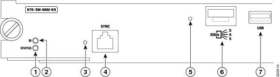
Figure 1 depicts the Cisco NAM-NX1 front panel. For a description of the front panel and LED operation, see Reading the NAM LEDs.
To connect your hardware module and configure the interface using the switch, see your Cisco Nexus 7000 Series Hardware Installation and Reference Guide .
Installing Prime NAM Software on the Module
This section covers installation scenarios of Prime NAM software on a Cisco Nexus 7000 Series Network Analysis Module.
NAM ships with Prime NAM software preinstalled. Review the two scenarios that cover installation options and determine which option best fits your needs:
1.
2.
After your initial installation, if you may want to upgrade to a later version of software if available. See Upgrading the Software for instructions.
Configuring the NAM Software
You must configure the switch to communicate with the NAM and then set the configuration settings on the NAM. Perform the following tasks in the order given:
1.
2.
Switch Configuration Examples for Placing the NAM in Service
This section includes the following example configurations required on the Cisco switch:
VLAN Management Port Configuration
This section describes the steps to follow in order to assign the NAM to a virtual device context (VDC) from the switch. The steps include:
1.
2.
3.
Once you complete these steps, continue to the next section to continue setting up a SPAN session to direct traffic to NAM. See SPAN Session from Nexus 7000 Series Switch.
This example shows how to configure a VLAN for NAM management traffic and how to assign that VLAN to the NAM management port. All commands must be executed in the VDC to which NAM belongs.
To assign the NAM to a virtual device context (VDC) from the switch:
Step 1
Step 2
a.

Note As long as the f2e keyword is present in the output, you can install the module in an empty slot and power it up. The interfaces will be allocated automatically. If the f2e keyword is missing (due to prior configuration), you need to add it as shown in step b. The f2e keyword must be present in the configuration before the module is powered up.
b.
Step 3
Step 4
Note
Step 5
SPAN Session from Nexus 7000 Series Switch
To share traffic between your switch and the NAM, you must create a SPAN session that sets the NAM as the destination for the Cisco Nexus 7000 switch traffic. This section provides two example SPAN sessions commands that set the NAM as the destination for the Cisco Nexus 7000 switch traffic.
destination analysis-module <module #> data-port <port #>
The following example shows the creation of a SPAN session from the Cisco NX-OS CLI. This is the preferred method to create the SPAN session.
In this example, a simple SPAN session is used to direct traffic received on interface 4/1 to data-port 1 on the NAM module. Use this example to create a similar SPAN session for your NAM.
Note
destination interface port-channel <port-channel #>
In this example, a SPAN session sets up the module as the destination using the port channel interface. Use your Nexus 7000 Series supervisor CLI setting to create a similar SPAN session for your NAM.
Note
For additional details on how to set up various traffic sources, see the Cisco Prime Network Analysis Module Software User Guide .
Getting the NAM Up and Running
After assigning the NAM to a VDC and setting up your SPAN network traffic, go to your VDC to set up the NAM IP configuration and enable the web server.
This section describes how to set the NAM IP configuration and enable the NAM web server and browser-based access to the NAM graphical user interface (GUI). After you perform these tasks, the NAM is in service. Each task includes a basic example. Your configuration setup may require different input.
Note
To configure the module’s network configuration parameters:
Step 1
Note Ensure that you are in the correct VDC. You can use the switchto vdc command to change VDCs.
If you have not changed the root password, enter a new password to ensure security.

Tip The default username and password for the NAM is root/root. As part of the installation, change the password first, although the NAM accepts anything including the default.
Step 2
Step 3
a.
b.
Step 4
Note
Step 5
Step 6
The NAM is now on the network and is accessible using the management IP address.
Step 7
Note
The only access to the NAM web server is the administrative user you configured when you enabled the web server. There is no secondary user option. To configure more users, see the Prime NAM Command Reference Guide or the Prime NAM User Guide on Cisco.com .
Installing and Configuring External Storage
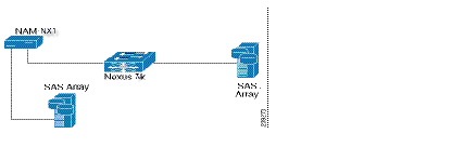
The Cisco Nexus 7000 Series Network Analysis Module offers external storage connectivity for extended capture durations and higher capture bandwidths.
This connectivity is provided through the Mini Serial Attached SCSI (SAS, SFF-8088). The external SAS storage array is directly attached.
See Figure 2 for an overview of external data storage setup.
Figure 2 External Storage Setup
Configure the Storage Array
Reference your vendor user guide for proper configuration of the array. The NAM is independent of most array settings, but some are important for accessibility and performance.
When configuring the Logical Unit Numbers (LUNs) on the array, there is often a Segment Size setting. Larger segment sizes can improve write speeds. Use a segment size as large as possible, up to 512 KB. Multiple LUNs can be configured on a single array. This module supports up to 32 LUNs.
It is important to map the module SAS address to the LUNs. Most storage arrays require this mapping for security reasons, ensuring that only certain hosts (for example, a NAM) can access the LUNs. Each NAM has a unique SAS address, so this step must be performed for each NAM and for each LUN.
The NAM SAS address can be found using the CLI command remote-storage sas local-address . Many storage arrays automatically detect the SAS address once connected to the NAM.
Some SAS storage arrays do not properly negotiate the SAS base address of the front panel port. The port is a wide port because it consists of four SAS lanes. Each lane has its own SAS address, and any one of the four addresses can be considered the base address for the wide port. Ensure you map all four SAS addresses in the storage array configuration.
The previous remote storage CLI command returned a SAS address of 5003223000000000 for the first lane. The other three lanes have consecutive addresses: 5003223000000001, 5003223000000002, and 5003223000000003. All four of those addresses need to be mapped in the storage array configuration.
Connect the Storage Array
After the storage array is configured, connect it to the NAM using the SFF-8088 cable. The module supports SFF-8088 cables up to 6 M. Be sure to use the correct host-connect port on the array as indicated by the vendor user guide. The array can be connected while the NAM is running.
Some arrays come with multiple storage controller modules, and the module ownership must often be mapped to each LUN. This mapping is a common security feature.
The LUN number can help you identify one LUN from others of the same external storage array. This number is unique to each particular array, meaning two LUNs from different arrays can have the same number. If the new LUNs do not show up in the list, then the NAM cannot access them. This problem is likely due to a configuration error on the array.
You can now use the SAS external storage from within the NAM. For more information, see the Cisco Prime Network Analysis Module Software User Guide .
Upgrading and Recovering Your Software
Cisco occasionally provides upgrades to Prime NAM software that you can download and install on your module. You may also need to restore your module software in the case of a catastrophic failure.
Before upgrading your NAM software, we recommend that you backup your configuration as explained in Backing Up Your Configuration.
After upgrading or restoring your module software, you can restore that configuration and resume network monitoring if you previously backed up your configuration.
To perform a new software installation or upgrade, download a version of the current Prime NAM software and use a single CLI command.
To upload your saved configuration to an archive server, use the command-line interface.
To perform a recovery installation when your can no longer boot the NAM application, use the helper utility.
To restore your previous NAM configuration, use the command-line interface. (Optional)
Backing Up Your Configuration
Before you begin the upgrade process, we recommend that you perform a complete backup of your current NAM configuration. This includes the unique changes you have made to the NAM using the GUI or CLI. Any local data is not saved.
Note
To back up your current configuration, use the NAM CLI config upload command like the following:
config upload ftp:// user:password@server//path/filename
config upload ftp:// admin:secret@10.10.10.10//archive/nam_config
The config upload command sends a copy of the NAM running configuration to the destination you specify. The copy of your configuration is stored in a back-up configuration file with an ending suffix of .config as in NAM _host-nam-nx1-6.0.config . The destination address must be a valid server name and directory path where you have read and write permissions. If a filename is not identified, NAM creates a default file name.
Upgrading the Software
To install the software if the module is not booting properly or to upgrade to a newer software version:
Step 1
http://software.cisco.com/download/navigator.html
Step 2
Step 3
Step 4
For example, use the NAM CLI command upgrade to perform the software upgrade:
Performing a Recovery Installation
If your module suffers a catastrophic event, such as hard disk corruption, and you can no longer boot the NAM application, use the helper utility to reinstall Cisco Prime NAM application software.
To access the helper utility to install the NAM recovery and NAM software images, perform the following procedure on the switch CLI console:
Note
Step 1
The recovery helper file contains the term helper (for example, nam-app-x86_64.6-0-1-lfbff-helper.SSA ).
Step 2
where X is the slot where the NAM module is placed and YY is the routable VLAN to use for NAM connectivity.
Step 3
where X is the slot where the NAM module is located.
Step 4
where X is the slot number where the NAM module is located.
You see a boot up sequence on the session terminal, or a rommon prompt. You must get to the rommon prompt to start the recovery process.
Look for this output during bootup:
Step 5
Step 6
The following list describes the parameters that must be set:
–
–
–
–
–
–
where 10.1.2.3 is a running TTP server reachable from the supervisor and IMG_FILE is set to your path and NAM filename.
Step 7
Step 8
At some point, the menu displays:
Step 9
Step 10
Step 11
Step 12
Download NAM application image via ftp/http and reformat & write to HDD URL of application image []:Step 13
Step 14
Once the installation is complete, the main menu displays.
Step 15
If you are still on the console, you see the rommon bootup sequence as well as the NAM bootup sequence. Wait for the NAM login prompt. No user interaction is needed until that point is reached.
Step 16
The NAM CLI displays. The recovery is complete.
To configure the NAM, proceed to the Getting the NAM Up and Running. Then, if available, restore any saved data once the configuration is complete.
Restoring Your Configuration
To restore your NAM configuration file after a system recovery, access the NAM configuration back-up file using FTP or HTTP.
config network ftp:// user:password@server//path/filename
config network ftp:// admin:secret@172.10.10.11//archive/nam_config/NAM_host-nam-nx1.6.x.x.config
Performing Advanced Tasks
This section describes some advanced tasks that you may need to perform.
- Resetting the NAM Root Password to the Default Value
- Accessing NAM Using a Telnet or SSH Session
- Moving Your NAM to a New VDC
Resetting the NAM Root Password to the Default Value
If you have forgotten the root password and need to reset it to the default value, enter the following from the switch: clear service module slot x password .
For information about how to reset the NAM root password to the default value from the NAM, see the Cisco Prime Network Analysis Module Software User Guide .
Accessing NAM Using a Telnet or SSH Session
This procedure explains how to open and close a Telnet or SSH session to the NAM. This procedure is not commonly performed, because you would typically use the NAM GUI to monitor and maintain the NAM. If, however, you cannot access the GUI, you may want to use Telnet or SSH to troubleshoot from the NAM CLI.
- Configure the NAM system IP address. Optionally, set the NAM system hostname.
- Verify NAM network connectivity by performing one of the following ping tests:
–
–
Step 1
or
ssh { ip-address | hostname }Step 2
Step 3
or
If you have not changed the password from the factory-set default, enter root as the root password.Step 4
For more details on NAM CLI, see the Prime NAM Command Reference Guide .
Examples
Opening and Closing a Telnet Session to the NAM Using the NAM System IP Address
Opening and Closing an SSH Session to the NAM Using the NAM System Hostname
Moving Your NAM to a New VDC
This section describes how to move your NAM to another virtual device context (VDC).
Before you begin, ensure the VDC has been created and is set to accept F2e type modules.
Add the f2e keyword if it is not present in the configuration.
For more details on how to check if the NAM can be moved to your VDC, see your Cisco Nexus 7000 product documentation.
Ensure that you are in the correct VDC by using the switchto vdc command.
The following example shows the commands to perform for the move.
Troubleshooting and Reference
The service modules undergo extensive testing before they leave the factory. If you encounter problems, use the information in this section to help isolate problems or to eliminate the module as the source of the problem.
Note
This section covers some trouble events that may occur on a module. It focuses on those events that may frequently occur.
- Troubleshooting Guidelines
- Shutting Down and Starting Up the Cisco NAM-NX1
- Reading the NAM LEDs
- Replacing the NAM Memory or Hard Disk
More troubleshooting and frequently asked questions can be found in the Cisco Prime Network Analysis Module Software User Guide .
Shutting Down and Starting Up the Cisco NAM-NX1

Caution Do not remove the NAM from the switch until the module has shut down completely and the STATUS LED is OFF. You risk disk corruption if you remove the module from the switch before the NAM completely shuts down.
To avoid corrupting the NAM hard disk, you must correctly shut down the NAM before you remove it from the chassis or disconnect the power. You can initiate this shutdown procedure by entering commands at the supervisor module CLI prompt or the NAM CLI prompt. To ensure a graceful shutdown, use the CLI command out-of-service module <module_number> .
Step 1
Note Ensure that you are in the correct VDC. You can use the switchto vdc command to change VDCs.
Note
The shutdown process can take several minutes. The STATUS LED turns off when the NAM shuts down and then blinks red. For more details on the shutdown and start up commands, see the Cisco Prime NAM Command Reference Guide .
Reading the NAM LEDs
This section describes the location and meaning of the LEDs for the module.
Figure 1 shows the front-panel LEDs for the NAM module. Table 1 defines the LED states.
Table 2 Front Panel LED Descriptions
Replacing the NAM Memory or Hard Disk
The NAM memory or hard disk can be replaced using the following instructions:
Note
Warning Use an ESD or antistatic wrist strap, a conductive foam pad or mat (recommended), and follow all necessary antistatic standards when handling hard disk drives.
Step 1
Step 2
Step 3
Step 4
Step 5
Step 6
Step 7
Using the CLI Helper Utility for System Administrative Tasks
You can use the CLI helper utility to perform the following administrative tasks:
- Configuring Network Parameters
- Downloading an Application Image and Writing to HDD
- Downloading an Application Image and Reformatting the HDD
- Displaying Software Versions
- Resetting Application Image CLI Passwords to Default
- Changing the System File Transfer Method
- Confirming Network Connectivity Using Ping
- Formatting Boot Flash
- Accessing Upgrade History
- Fixing Local Disk Errors
- Rebooting a New Application Image
- Shutting Down the Service Module
For information about accessing the helper utility, see Performing a Recovery Installation.
Note
The following sections describe the Helper Utility Menu, what each option does, and any requirements for using a particular option.
Helper Utility Menu Summary
Configuring Network Parameters
Use Option n to configure the network parameters for the software.
Step 1
Step 2
Downloading an Application Image and Writing to HDD
Use Option 1 to download a version of the current application image from an FTP server location and write the image to the hard disk.
Note
This option downloads a version of the current application from an FTP server location or from a location you can access using HTTP. You can also download the latest the NAM software version from Cisco.com.
This URL requires you to have a Cisco service agreement and access to the Internet to download the zipped software.
Downloading an Application Image and Reformatting the HDD
Use Option 2 to download the current application image and write the image to the hard disk.
Caution Using this option reformats the hard disk before writing the application image and destroys all data such as reports, packet captures, and configuration. Network connectivity configuration, however, is retained.
Note
This option downloads a version of the current application image from an FTP server location or from a location you can access using HTTP. You can also download the latest the NAM software version from Cisco.com.
This URL requires you to have a Cisco service agreement and access to the Internet to download the zipped software.
Displaying Software Versions
Use Option 3 to display the current software application image version stored on your hard disk.
Resetting Application Image CLI Passwords to Default
Use Option 4 to reset the password for users root and admin to their default values.
Changing the System File Transfer Method
Use Option 5 to change the file transfer method. This option is only necessary if you change the file transfer method by mistake. Only FTP and HTTP are supported.
Confirming Network Connectivity Using Ping
Use Option 6 to send a ping to determine if network connectivity exists. When prompted, enter the IP address or full domain name of the location to send the ping.
Formatting Boot Flash
This option is mainly used by the manufacture.
Use Option 7 to format the bootflash.
If you choose to format the boot flash, you must reinstall NAM image. We recommend you use this option only if instructed to do so.
Rebooting a New Application Image
Use Option r to exit the helper utility and power cycle (reboot) into the newly installed application image.
Switch CLI Quick Reference
This section includes several switch commands you can use to verify the NAM:
To view the current users and to which line they are associated, use the show users command.
From the switch CLI execution mode, issue this command:
show module # version / show analysis module x version
To identify the version of the NAM software on the switch, use the show module or show analysis module commands:
To verify the state of the NAM (active or inactive), use the show service nam summary command:
Related Documentation
The following sections provide references related to the Cisco Nexus 7000 Series Network Analysis Module features.
Cisco Network Analysis Module (NAM) Software at http://www.cisco.com/en/US/products/sw/cscowork/ps5401/
tsd_products_support_series_home.htmlCisco Network Modules and Interface Cards Regulatory Compliance and Safety Information at http://www.cisco.com/en/US/products/ps9402/prod_installation_guides_list.html
Cisco Nexus 7000 Series NX-OS Interfaces Command Reference at http://www.cisco.com/en/US/products/ps9402/prod_command_reference_list.html
Obtaining Documentation and Submitting a Service Request
For information on obtaining documentation, using the Cisco Bug Search Tool (BST), submitting a service request, and gathering additional information, see What’s New in Cisco Product Documentation at: http://www.cisco.com/c/en/us/td/docs/general/whatsnew/whatsnew.html .
Subscribe to What’s New in Cisco Product Documentation , which lists all new and revised Cisco technical documentation, as an RSS feed and deliver content directly to your desktop using a reader application. The RSS feeds are a free service.
Cisco and the Cisco logo are trademarks or registered trademarks of Cisco and/or its affiliates in the U.S. and other countries. To view a list of Cisco trademarks, go to this URL: www.cisco.com/go/trademarks . Third-party trademarks mentioned are the property of their respective owners. The use of the word partner does not imply a partnership relationship between Cisco and any other company. (1110R)
 Feedback
Contact Cisco
- Open a Support Case

- (Requires a Cisco Service Contract)