Configuring Modular QoS Service Packet Classification

This chapter covers these topics:

Packet Classification Overview

Packet classification involves categorizing a packet within a specific group (or class) and assigning it a traffic descriptor to make it accessible for QoS handling on the network. The traffic descriptor contains information about the forwarding treatment (quality of service) that the packet should receive. Using packet classification, you can partition network traffic into multiple priority levels or classes of service. The source agrees to adhere to the contracted terms and the network promises a quality of service. Traffic policers and traffic shapers use the traffic descriptor of a packet to ensure adherence to the contract.

Traffic policers and traffic shapers rely on packet classification features, such as IP precedence, to select packets (or traffic flows) traversing a router or interface for different types of QoS service. After you classify packets, you can use other QoS features to assign the appropriate traffic handling policies including congestion management, bandwidth allocation, and delay bounds for each traffic class.

The Modular Quality of Service (QoS) CLI (MQC) defines the traffic flows that must be classified, where each traffic flow is called a class of service, or class. Later, a traffic policy is created and applied to a class. All traffic not identified by defined classes fall into the category of a default class.

Guidelines and Limitations

  • Ingress CoS marking is not supported on Cisco NCS 5500 Series routers; however, it is supported on Cisco NCS 5700 Series routers.


    Note


    Ingress CoS marking is not supported on L3 interfaces because it can overwrite the Port Control Protocol (PCP) for traffic passing through the core network. To implement CoS marking, always configure it on egress L2 interfaces.


Traffic Class Elements

Default Traffic Class

Unclassified traffic (traffic that does not meet the match criteria specified in the traffic classes) is treated as belonging to the default traffic class.

If the user does not configure a default class, packets are still treated as members of the default class. However, by default, the default class has no enabled features. Therefore, packets belonging to a default class with no configured features have no QoS functionality. These packets are then placed into a first in, first out (FIFO) queue and forwarded at a rate determined by the available underlying link bandwidth.

For egress classification, match on traffic-class (1-7) is supported. Match traffic-class 0 cannot be configured. The class-default in the egress policy maps to traffic-class 0 .

This example shows how to configure a traffic policy for the default class:


configure
 policy-map ingress_policy1
 class class-default
  police rate percent 30
 !

Create a Traffic Class

To create a traffic class containing match criteria, use the class-map command to specify the traffic class name, and then use the match commands in class-map configuration mode, as needed.

Guidelines

  • Match criteria evaluation order: You can provide multiple values for a match type in a single line of configuration; that is, if the first value does not meet the match criteria, then the next value indicated in the match statement is considered for classification.

  • Excluding values with not keyword: Use the not keyword with the match command to perform a match based on the values of a field that are not specified.

  • Match commands are optional, but one required: All match commands specified in this configuration task are optional, but you must configure at least one match criterion for a class.

  • match-any versus match-all behavior: If you specify match-any , one of the match criteria must be met for traffic entering the traffic class to be classified as part of the traffic class. This is the default. If you specify match-all , the traffic must match all the match criteria.

  • Packet length match support: From Release 7.11.1 onwards, for the match access-group command, QoS classification based on the packet length field in the IPv4 and IPv6 headers is supported. Prior to this, support was not available for packet length and TTL (time to live) fields.

  • Deny or empty ACLs not supported in class maps: For the match access-group command, when an ACL list is used within a class-map, the deny action of the ACL is ignored and the traffic is classified based on the specified ACL match parameters.

    An empty ACL (contains no rules, only remarks), when used within a class-map permits all traffic by default, and the implicit deny condition doesn’t work with an empty ACL. The corresponding class-map matches all traffic not yet matched by the preceding traffic classes.

  • Egress matching restrictions: The traffic-class and discard-class are supported only in egress direction, and these are the only match criteria supported in egress direction.

  • Default class matching behavior: The egress default class implicitly matches qos-group 0 for marking policy and traffic-class 0 for queuing policy.

  • No egress mapping for ingress classes: If you set a traffic class at the ingress policy and do not have a matching class at egress for the corresponding traffic class value, then the traffic at ingress with this class will not be accounted for in the default class at the egress policy map.

  • Only Class 0 maps to default class: Only traffic class 0 falls in the default class. A non-zero traffic class assigned on ingress but with no assigned egress queue, falls neither in the default class nor any other class.

  • EDM timeout during line card reload: EDM timeouts for show policy-map CLI commands are expected during line card reload with scale configuration.

  • Egress rate calculation variation on routers with Cisco NC57 line cards:

    • On Cisco NCS 5700 modular routers (in both compatibility and native modes), the show policy-map interface  command may display noticeable variations for the egress rates. The ingress rates are displayed accurately.

    • This behavior is specific to routers with external TCAM and more than one NPU. 

    • This behavior might not be noticeable when viewing the statistics for the first time but can become evident in subsequent checks. No action is required.

Configuration Example

You have to accomplish the following to complete the traffic class configuration:

  1. Creating a class map

  2. Specifying the match criteria for classifying the packet as a member of that particular class

    (For a list of supported match types, see Traffic Class Elements.)


Router# configure
Router(config)# class-map match-any qos-1
Router(config-cmap)# match qos-group 1
Router(config-cmap)# end-class-map
Router(config-cmap)# commit

Also see, Running Configuration.

Also see, Verification.

Related Topics

Associated Commands

Traffic Policy Elements

A traffic policy contains three elements:

  • Name

  • Traffic class

  • QoS policies

After choosing the traffic class that is used to classify traffic to the traffic policy, the user can enter the QoS features to be applied to the classified traffic.

The MQC does not necessarily require that the users associate only one traffic class to one traffic policy.

The order in which classes are configured in a policy map is important. The match rules of the classes are programmed into the TCAM in the order in which the classes are specified in a policy map. Therefore, if a packet can possibly match multiple classes, only the first matching class is returned and the corresponding policy is applied.

The router supports 32 classes per policy-map in the ingress direction and 8 classes per policy-map in the egress direction.

This table shows the supported class-actions on the router.

Supported Action Types

Direction supported on Interfaces

bandwidth-remaining*

egress

mark

(See Packet Marking)

police

ingress

priority

egress (level 1)

shape

egress

Create a Traffic Policy

The purpose of a traffic policy is to configure the QoS features that should be associated with the traffic that has been classified in a user-specified traffic class or classes.

To configure a traffic class, see Create a Traffic Class.

After you define a traffic policy with the policy-map command, you can attach it to one, or more interfaces to specify the traffic policy for those interfaces by using the service-policy command in interface configuration mode. With dual policy support, you can have two traffic policies, one marking and one queuing attached at the output. See, Attach a Traffic Policy to an Interface.

Configuration Example

You have to accomplish the following to complete the traffic policy configuration:

  1. Creating a policy map that can be attached to one or more interfaces to specify a service policy

  2. Associating the traffic class with the traffic policy

  3. Specifying the class-action(s) (see Traffic Policy Elements)

See, Running Configuration.

See, Verification.

Related Topics

Associated Commands

Attach a Traffic Policy to an Interface

After the traffic class and the traffic policy are created, you must attach the traffic policy to interface, and specify the direction in which the policy should be applied.

Configuration Example

You have to accomplish the following to attach a traffic policy to an interface:

  1. Creating a traffic class and the associated rules that match packets to the class (see )

  2. Creating a traffic policy that can be attached to one or more interfaces to specify a service policy (see Create a Traffic Policy )

  3. Associating the traffic class with the traffic policy

  4. Attaching the traffic policy to an interface, in the ingress or egress direction


Router# configure
Router(config)# 
Router(config-int)# service-policy output 
Router(config-int)# commit

Running Configuration

Verification

Related Topics

Associated Commands

    Packet Marking

    The packet marking feature provides users with a means to differentiate packets based on the designated markings.

    Egress packet marking

    L2 ingress marking

    VLAN tag details

    • Single tag operations: When symmetrical pop 1 action is performed, the outer tag (CoS, DEI) is retained as the original frame.

    Egress EXP Marking

    Table 1. Feature History Table

    Feature Name

    Release Information

    Feature Description

    Egress EXP bits Marking Support on Single-Label

    Release 7.11.1

    With this feature support, you can now mark MPLS EXP bits on single-label scenario.

    You can now design the QoS for your network based on either single-label or global label. If the directly connected peer router doesn’t advertise the explicit-null label, then the router encapsulates the packets with only the global label.

    Previously, the router was limited to mark MPLS EXP bits with a minimum of two labels. But even with a single EXP marking, you can prioritize certain types of traffic over others based on their importance.

    Supported Packet Marking Operations

    This table shows the supported packet marking operations.

    Table 2. Supported Ingress Marking Types

    Supported Mark Types

    Range

    Layer

    Supports Unconditional Marking

    Supports Conditional Marking

    Description

    DSCP

    0-63

    L3

    Ingress

    No

    Supported flows: IP to IP, IP to MPLS, MPLS to IP.

    precedence

    0-7

    L3

    Ingress

    No

    Supported flows: IP to IP, IP to MPLS, MPLS to IP.

    mpls experimental topmost

    0-7

    L3

    Ingress

    No

    Supported flows: MPLS to MPLS.

    mpls experimental imposition

    0-7

    L2

    L3

    Ingress

    No

    Supported flows: L2 to MPLS, IP to MPLS.

    DEI

    0-1

    L2

    Ingress

    No

    Supported flows: L2 to L2, L2 to MPLS.

    CoS

    0-7

    L2

    Ingress

    No

    Supported flows: L2 to L2, L2 to MPLS.

    discard-class

    0-2

    L2

    L3

    Ingress

    No

    Used in conjunction with random-detect for discard behavior identification.

    qos-group

    0-7

    L2

    L3

    Ingress

    No

    Marks traffic for QoS management.

    traffic-class

    0-7

    L2

    L3

    Ingress

    No

    Used for queuing purposes.

    Class-based Unconditional Packet Marking

    The packet marking feature allows you to partition your network into multiple priority levels or classes of service, as follows:

    • Use QoS unconditional packet marking to set the IP precedence or IP DSCP values for packets entering the network. Routers within your network can then use the newly marked IP precedence values to determine how the traffic should be treated.

      On ingress direction, after matching the traffic based on either the IP Precedence or DSCP value, you can set it to a particular discard-class. Weighted random early detection (WRED), a congestion avoidance technique, thereby uses discard-class values to determine the probability that a packet is dropped.

    • Use QoS unconditional packet marking to assign MPLS packets to a QoS group. The router uses the QoS group to determine how to prioritize packets for transmission. To set the traffic class identifier on MPLS packets, use the set traffic-class command in policy map class configuration mode.


      Note


      Setting the traffic class identifier does not automatically prioritize the packets for transmission. You must first configure an egress policy that uses the traffic class.

    Note


    • Unless otherwise indicated, the class-based unconditional packet marking for Layer 3 physical interfaces applies to bundle interfaces.


    Handling QoS for Locally Originated Packets

    What are Locally Originated Packets?

    Locally Originated Packets (LOPs) are packets generated and transmitted by the router itself. These differ from transit packets that pass through the router. LOPs include routing protocols, management protocols, and other locally initiated control messages.

    Default QoS markings for protocols

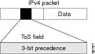
    The router assigns default precedence or Differentiated Services Code Point (DSCP) values to various locally originated protocols

    Protocol or application

    Precedence and DSCP value

    L2 PCP value

    BGP, OSPF, CCM (CSM), BFD, RSVP

    • Precedence: 6

    • DSCP: 48

    • BGP: 6 (with or without MPLS encap)

    • BFD: 7 (with or without MPLS encap)

    Telnet, SSH

    • Precedence: 2

    • DSCP: 16

    Not applicable

    SNMP

    Precedence: 0

    6 (with or without MPLS encap)

    SSH, SFTP

    Not applicable

    7 (with or without MPLS encap)

    Some protocols such as BGP, RSVP, CFM, and LDP and the management protocols allow setting explicit precedence or DSCP values.

    Traffic class assignment by Cisco IOS XR release

    Cisco IOS XR release

    Traffic class value

    Before Release 7.6.1

    • Locally generated control plane packets, such as IS-IS and BGP, are generated using traffic-class 6.

    • Locally generated BFD over Bundle (IETF) packets, which are generated on the Network Processing Unit (NPU), are generated using traffic-class 6.

    From Release 7.6.1 onwards

    • Locally generated control plane packets, such as IS-IS and BGP, are generated using traffic-class 7.

    • Locally generated BFD over Bundle (IETF) packets, which are generated on the Network Processing Unit (NPU), are generated using traffic-class 7.


    Note


    Bidirectional Forwarding Detection (BFD) uses a DSCP value of 63 (IP-ToS 255) for single-hop sessions and IP-ToS 0 for multi-hop sessions on the NCS540 router. Due to an SDK limitation, a DSCP value of 48 is not supported.


    Note


    Bidirectional Forwarding Detection (BFD) uses a DSCP value of 63 (IP-ToS 255) for single-hop sessions and IP-ToS 0 for multi-hop sessions on the NCS560 router. Due to an SDK limitation, a DSCP value of 48 is not supported.


    Managing datapath and locally originated packets

    On the router, datapath packets and injected packets aren’t differentiated if both their traffic classes share the same Virtual Output Queues (VOQs). Therefore, in the case of a congested VOQ, the LOCP packets are dropped. To avoid the LOCP packets drop, Cisco recommends that you have a different traffic class for data path traffic. Alternatively, you can also specify a higher bandwidth for traffic-class 7 (if ingress traffic rate is predictable).

    Optimizing traffic handling by early classification and marking

    Classifying traffic helps the router to recognize traffic as a certain type and mark that traffic. By marking traffic early on its travel, you can prevent excessive reclassification later. You can mark traffic at the protocol level as shown in the following examples:

    Ethernet

    The following configuration shows that the outbound Control Hub packets are marked with a precedence value of 2 and EXP of 2, instead of a precedence and EXP value of 6. The SSH packets have a precedence value of 3 instead of 2.

    ethernet cfm
      mep domain FOO service FOOBAR mep-id 1
       cos 2
    ssh server dscp 24

    BGP

    neighbor x.x.x.x dscp

    MPLS LDP

    mpls ldp signalling dscp

    Telnet

    telnet ipv4 dscp
    

    SNMP

    snmp-server ipv4 precedence/dscp

    Syslog

    logging ipv4 precedence/dscp
    netflow
    flow exporter-map TEST dscp

    NTP

    ntp ipv4 precedence/dscp
    ssh client dscp 56
    ssh server dscp 56

    Note


    By default, the router marks the Precision Time Protocol (PTP) traffic as high priority. Therefore, the need to prioritize PTP traffic in the QoS configuration is not required.


    LOCPs and QoS policies

    LOCPs are packets generated by the router itself, such as IS-IS, ARP, and other non-IP-based control packets. These packets are critical for network operations and are treated with high priority to ensure they are not dropped under normal circumstances.


    Note


    By default, all LOCPs are assigned to traffic-class 7. Considering that LOCPs and LOMPs are generated by the RP, an Ingress QoS policy cannot be applied. Therefore, you must ensure that the egress QoS policy includes a class-map which matches traffic-class 7. By definition, the egress QoS policy matches all implicitly marked packets.


    Key features of LOCPs

    Discard priority

    • LOCPs originating from the RP or LC CPU have a discard priority set in the appended Buffer Header (BHDR).

    • This ensures LOCPs are not dropped internally under normal conditions.

    • LOMPs do not have this discard priority and are treated as normal traffic.

    Queue management

    • LOCPs with discard priority are placed in an implicitly allocated high-priority queue for each physical egress interface.

    • During congestion, LOCPs are not subject to Weighted Random Early Detection (WRED) or Tail-drop queue-limit operations.

    • The tail-drop queue-limit must be hit before LOCP packets are dropped.

    QoS policy configuration

    • QoS policies can be attached to physical interfaces or sub-interfaces.

    • If attached to sub-interfaces, the operator cannot attach a QoS policy to the physical interface.

    • LOCPs are always sent out on the default high-priority queue of the physical interface.

    Bandwidth reservation

    • A minimum bandwidth of MIN (1% of interface bandwidth, 10 Mbps) is reserved for the default high-priority queue on physical interfaces without a QoS policy.

    • If a QoS policy is applied, the minimum bandwidth for the high-priority queue is controlled by the configured policy.

    Classification and re-marking

    • LOCPs are not subject to traffic policing or re-marking.

    • Non-IP LOCPs, such as IS-IS and ARP, are always sent to the high-priority queue, irrespective of the QoS policy.

    Session termination prevention

    • During over-subscription, LOCP drops may occur, leading to session termination.

    • Proper bandwidth allocation and QoS configuration are essential to prevent such scenarios.

    QoS packet marking across network layers

    QoS packet marking is a networking management technique used to classify and prioritize data packets. Using this, you can enable the application of traffic handling policies such as bandwidth allocation and congestion management.

    This table describes the key QoS fields in packet headers.

    Table 3.

    Field

    Layer

    Purpose

    L3 DSCP

    Layer 3

    Classify and prioritize packets in the IP header.

    MPLS EXP

    Layer 2.5 (MPLS)

    Carry QoS information in MPLS networks.

    QoS Group

    Cisco

    Internal classification for flexible QoS policy application.

    Traffic Class

    Layer 3 (IPv6)

    Define QoS policies in IPv6 headers.

    L2 PCP

    Layer 2

    Prioritize traffic in Ethernet networks using the 802.1Q VLAN tag.

    QoS packet marking across network layers is explained with and without MPLS encapsulation.

    QoS packet marking across network layers with MPLS encapsulation

    In MPLS networks, the QoS marking is done using the 3-bit MPLS EXP field in the MPLS label. This field is used to classify and prioritize traffic as it traverses the MPLS network. The EXP field is often derived from the IP precedence or DSCP value of the original packet at the ingress of the MPLS network.

    This table illustrates how QoS packet marking is applied to network protocols when using MPLS encapsulation across various large density routers.

    Table 4.

    Router

    Routing Protocol

    L3 DSCP

    MPLS EXP

    QoS group

    Traffic class

    L2 PCP

    Large

    • N540-24Q8L2DD-SYS

    • N540-24Q2C2DD-SYS

    BFD

    Cs6

    6

    QG6

    7

    6

    BFD (HW Offload)

    Cs6

    6

    QG6

    7

    6

    SRPM

    Cs6

    6

    QG6

    7

    6

    SRPM (NPU Offload)

    Cs6

    6

    QG6

    7

    6

    ISIS

    NA

    6

    QG6

    7

    6

    BGP

    Cs6

    6

    QG6

    7

    6

    SSH/SFTP

    Cs6

    6

    QG6

    7

    6

    NTP

    Cs6

    6

    QG6

    7

    6

    TACACS

    Cs6

    6

    QG6

    7

    6

    SNMP

    Cs6

    6

    QG6

    7

    6

    SYSLOG

    Cs6

    6

    QG6

    7

    6

    This table illustrates how QoS packet marking is applied to network protocols when using MPLS encapsulation across various medium density routers.

    Router

    Routing Protocol

    L3 DSCP

    MPLS EXP

    QoS group

    Traffic class

    L2 PCP

    Medium

    • N540-ACC-SYS

    • N540X-ACC-SYS

    • N540-24Z8Q2C-SYS

    • N540X-16Z4G8Q2C-D/A

    • N540X-16Z8Q2C-D

    • N540-28Z4C-SYS-D/A

    • N540X-12Z16G-SYS-D/A

    • N540-12Z20G-SYS-D/A

    BFD

    Cs6

    6

    QG7

    7

    7

    BFD (HW Offload)

    Cs6

    6

    QG7

    7

    7

    SRPM

    Cs7

    6

    QG7

    7

    7

    SRPM (NPU Offload)

    Cs7

    6

    QG7

    7

    7

    ISIS

    NA

    6

    QG7

    7

    7

    BGP

    Cs6

    6

    QG6

    7

    6

    SSH/SFTP

    Cs6

    6

    QG6

    7

    6

    NTP

    Cs6

    6

    QG6

    7

    6

    TACACS

    Cs6

    6

    QG6

    7

    6

    SNMP

    Cs6

    6

    QG6

    7

    6

    SYSLOG

    Cs6

    6

    QG6

    7

    6

    ICMP

    Cs7

    6

    QG7

    7

    6

    This table illustrates how QoS packet marking is applied to network protocols when using MPLS encapsulation across various small density routers.

    Router

    Routing Protocol

    L3 DSCP

    MPLS EXP

    QoS group

    Traffic class

    L2 PCP

    Small

    • N540X-4Z14G2Q-D/A

    • N540X-8Z16G-SYS-D/A

    • N540X-6Z18G-SYS-D/A

    • N540-6Z18G-SYS-D/A

    • N540-6Z14S-SYS-D

    BFD

    Cs6

    6

    QG7

    7

    7

    BFD (HW Offload)

    Cs6

    6

    QG7

    7

    7

    SRPM

    Cs7

    6

    QG7

    7

    7

    SRPM (NPU Offload)

    Cs7

    6

    QG7

    7

    7

    ISIS

    NA

    6

    QG7

    7

    7

    BGP

    Cs6

    6

    QG6

    7

    6

    SSH/SFTP

    Cs6

    6

    QG6

    7

    7

    NTP

    Cs6

    6

    QG6

    7

    6

    TACACS

    Cs6

    6

    QG6

    7

    6

    SNMP

    Cs6

    6

    QG6

    7

    6

    SYSLOG

    Cs6

    6

    QG6

    7

    6

    ICMP

    Cs6

    6

    QG6

    7

    6

    QoS packet marking across network layers without MPLS encapsulation

    The layerwise QoS packet marking refers to the classification and marking of packets at different layers to prioritize traffic based on QoS policies.

    This table shows how QoS packet marking is applied without MPLS encapsulation across various large density routers.

    Table 5.

    Router

    Routing Protocol

    L3 DSCP

    QoS group

    Traffic class

    L2 PCP

    Large

    • N540-24Q8L2DD-SYS

    • N540-24Q2C2DD-SYS

    BFD

    Cs6

    QG6

    7

    6

    BFD (HW Offload)

    Cs6

    QG6

    7

    6

    SRPM

    Cs6

    QG6

    7

    6

    SRPM (NPU Offload)

    Cs6

    QG6

    7

    6

    ISIS

    NA

    QG6

    7

    6

    BGP

    Cs6

    QG6

    7

    6

    SSH/SFTP

    Cs6

    QG6

    7

    6

    NTP

    Cs6

    QG6

    7

    6

    TACACS

    Cs6

    QG6

    7

    6

    SNMP

    Cs6

    QG6

    7

    6

    SYSLOG

    Cs6

    QG6

    7

    6

    This table shows how QoS packet marking is applied without MPLS encapsulation across various medium density routers.

    Router

    Routing Protocol

    L3 DSCP

    QoS group

    Traffic class

    L2 PCP

    Medium

    • N540-ACC-SYS

    • N540X-ACC-SYS

    • N540-24Z8Q2C-SYS

    • N540X-16Z4G8Q2C-D/A

    • N540X-16Z8Q2C-D

    • N540-28Z4C-SYS-D/A

    • N540X-12Z16G-SYS-D/A

    • N540-12Z20G-SYS-D/A

    BFD

    Cs6

    QG7

    7

    7

    BFD (HW Offload)

    Cs6

    QG7

    7

    7

    SRPM

    Cs7

    QG7

    7

    7

    SRPM (NPU Offload)

    Cs7

    QG7

    7

    7

    ISIS

    NA

    QG7

    7

    7

    BGP

    Cs6

    QG6

    7

    6

    SSH/SFTP

    Cs6

    QG6

    7

    6

    NTP

    Cs6

    QG6

    7

    6

    TACACS

    Cs6

    QG6

    7

    6

    SNMP

    Cs6

    QG6

    7

    6

    SYSLOG

    Cs6

    QG6

    7

    6

    ICMP

    Cs6

    QG6

    7

    6

    This table shows how QoS packet marking is applied without MPLS encapsulation across various small density routers.

    Router

    Routing Protocol

    L3 DSCP

    QoS group

    Traffic class

    L2 PCP

    Small

    • N540X-4Z14G2Q-D/A

    • N540X-8Z16G-SYS-D/A

    • N540X-6Z18G-SYS-D/A

    • N540-6Z18G-SYS-D/A

    • N540-6Z14S-SYS-D

    BFD

    Cs6

    QG7

    7

    7

    BFD (HW Offload)

    Cs6

    QG7

    7

    7

    SRPM

    Cs7

    QG7

    7

    7

    SRPM (NPU Offload)

    Cs7

    QG7

    7

    7

    ISIS

    NA

    QG7

    7

    7

    BGP

    Cs6

    QG6

    7

    6

    SSH/SFTP

    Cs6

    QG6

    7

    7

    NTP

    Cs6

    QG6

    7

    6

    TACACS

    Cs6

    QG6

    7

    6

    SNMP

    Cs6

    QG6

    7

    6

    SYSLOG

    Cs6

    QG6

    7

    6

    ICMP

    Cs6

    QG6

    7

    6

    Protecting Locally Originated BFD Packets

    For releases before Release 7.6.1, BFD packets are injected into traffic-class 6, with drop priority 0 (equivalent of discard-class 0). If transit traffic is also classified into traffic-class 7 and the associated egress queue is congested, BFD packets may be dropped.

    From Release 7.6.1, BFD packets are injected into traffic-class 7, with drop priority 0 (equivalent of discard-class 0). If transit traffic is also classified into traffic-class 7 and the associated egress queue is congested, BFD packets may be dropped.

    The recommendation is to configure transit traffic-class 7 in the ingress QoS policy with discard-class 1 or 2. You must then configure WRED in the egress QoS policy that drops these packets before dropping discard-class 0.


    Note


    The default queue length is 16 ms.


    Example

    class-map match-any NC
     match traffic-class 6 (for releases before Release 7.6.1)
     match traffic-class 7 (from Release 7.6.1)
    !
    policy-map CORE-OUT
     class NC
      random-detect discard-class 1 7 ms 8 ms
    

    Hardware Programming

    RP/0/RP0/CPU0:R26-Spine2-5508#sh qos interface hu0/0/0/35 output
    NOTE:- Configured values are displayed within parentheses
    Interface HundredGigE0/0/0/35 ifh 0x1408  -- output policy
    NPU Id:                        5
    Total number of classes:       2
    Interface Bandwidth:           100000000 kbps
    Policy Name:                 7  wred-out
    SPI Id:                        0x0
    VOQ Base:                      1592
    Accounting Type:               Layer1 (Include Layer 1 encapsulation and above)
    ------------------------------------------------------------------------------
    Level1 Class                             =   NC
    Egressq Queue ID                         =   1598 (LP queue)
    Queue Max. BW.                           =   20480000 kbps (20 %)
    Queue Min. BW.                           =   0 kbps (default)
    Inverse Weight / Weight                  =   1 / (BWR not configured)
    Guaranteed service rate                  =   20000000 kbps
    Peak burst                               =   33600 bytes (default)
    TailDrop Threshold                       =   40108032 bytes / 16 ms (default)
    
    WRED profile for Discard_Class 1
    WRED Min. Threshold                      =   17563648 bytes (7 ms)
    WRED Max. Threshold                      =   20054016 bytes (8 ms)
    
    Default RED profile
    WRED Min. Threshold                      =   0 bytes (0 ms)
    WRED Max. Threshold                      =   0 bytes (0 ms)
    
    WRED ECN                                 =   Disabled

    Bundle Traffic Policies

    A policy can be bound to bundles. When a policy is bound to a bundle, the same policy is programmed on every bundle member (port). For example, if there is a policer or shaper rate, the same rate is configured on every port. Traffic is scheduled to bundle members based on the load balancing algorithm.

    Both ingress and egress traffic is supported. Percentage-based policies are supported.

    For details, see Configure QoS on Link Bundles.

    In-Place Policy Modification

    The In-Place policy modification feature allows you to modify a QoS policy even when the QoS policy is attached to one or more interfaces. A modified policy is subjected to the same checks that a new policy is subject to when it is bound to an interface. If the policy-modification is successful, the modified policy takes effect on all the interfaces to which the policy is attached. However, if the policy modification fails on any one of the interfaces, an automatic rollback is initiated to ensure that the pre-modification policy is in effect on all the interfaces.

    You can also modify any class map used in the policy map. The changes made to the class map take effect on all the interfaces to which the policy is attached.


    Note


    • The QoS statistics for the policy that is attached to an interface are lost (reset to 0) when the policy is modified.

    • When a QoS policy attached to an interface is modified, there might not be any policy in effect on the interfaces in which the modified policy is used for a short period of time.

    • The system does not support the show policy-map statistics for marking policies.

    • An in-place modification of an ACL does not reset the policy-map statistics counter.


    Note


    • For QOS EXP-Egress marking applied on a Layer 3 interface on Cisco routers, there is a limit of two unique policy-maps per NPU. When the maximum limit for policy-maps is reached and you try to modify a policy-map which is shared between different interfaces, you may get an error.

    • For QOS egress marking (CoS, DEI) applied on a Layer 2 interface, there is a limit of 13 unique policy-maps per NPU. When the maximum limit for policy-maps is reached and you try to modify a policy-map which is shared between different interfaces, you may get an error.


    Verification

    If unrecoverable errors occur during in-place policy modification, the policy is put into an inconsistent state on target interfaces. No new configuration is possible until the configuration session is unblocked. It is recommended to remove the policy from the interface, check the modified policy and then re-apply accordingly.

    References for Modular QoS Service Packet Classification

    Specification of the CoS for a Packet with IP Precedence

    Use of IP precedence allows you to specify the CoS for a packet. You can create differentiated service by setting precedence levels on incoming traffic and using them in combination with the QoS queuing features. So that, each subsequent network element can provide service based on the determined policy. IP precedence is usually deployed as close to the edge of the network or administrative domain as possible. This allows the rest of the core or backbone to implement QoS based on precedence.

    Figure 1. IPv4 Packet Type of Service Field

    You can use the three precedence bits in the type-of-service (ToS) field of the IPv4 header for this purpose. Using the ToS bits, you can define up to eight classes of service. Other features configured throughout the network can then use these bits to determine how to treat the packet in regard to the ToS to grant it. These other QoS features can assign appropriate traffic-handling policies, including congestion management strategy and bandwidth allocation. For example, queuing features such as LLQ can use the IP precedence setting of the packet to prioritize traffic.

    IP Precedence Bits Used to Classify Packets

    Use the three IP precedence bits in the ToS field of the IP header to specify the CoS assignment for each packet. You can partition traffic into a maximum of eight classes and then use policy maps to define network policies in terms of congestion handling and bandwidth allocation for each class.

    Each precedence corresponds to a name. IP precedence bit settings 6 and 7 are reserved for network control information, such as routing updates. These names are defined in RFC 791.

    IP Precedence Value Settings

    By default, the routers leave the IP precedence value untouched. This preserves the precedence value set in the header and allows all internal network devices to provide service based on the IP precedence setting. This policy follows the standard approach stipulating that network traffic should be sorted into various types of service at the edge of the network and that those types of service should be implemented in the core of the network. Routers in the core of the network can then use the precedence bits to determine the order of transmission, the likelihood of packet drop, and so on.

    Because traffic coming into your network can have the precedence set by outside devices, we recommend that you reset the precedence for all traffic entering your network. By controlling IP precedence settings, you prohibit users that have already set the IP precedence from acquiring better service for their traffic simply by setting a high precedence for all of their packets.

    The class-based unconditional packet marking and LLQ features can use the IP precedence bits.

    IP Precedence Compared to IP DSCP Marking

    If you need to mark packets in your network and all your devices support IP DSCP marking, use the IP DSCP marking to mark your packets because the IP DSCP markings provide more unconditional packet marking options. If marking by IP DSCP is undesirable, however, or if you are unsure if the devices in your network support IP DSCP values, use the IP precedence value to mark your packets. The IP precedence value is likely to be supported by all devices in the network.

    You can set up to 8 different IP precedence markings and 64 different IP DSCP markings.