Multicast Configuration Guide for Cisco NCS 5000 Series Routers, IOS XR Release 6.3.x
Bias-Free Language
The documentation set for this product strives to use bias-free language. For the purposes of this documentation set, bias-free is defined as language that does not imply discrimination based on age, disability, gender, racial identity, ethnic identity, sexual orientation, socioeconomic status, and intersectionality. Exceptions may be present in the documentation due to language that is hardcoded in the user interfaces of the product software, language used based on RFP documentation, or language that is used by a referenced third-party product. Learn more about how Cisco is using Inclusive Language.
- Updated:
- March 29, 2018
Chapter: Implementing Multicast
- Implementing Layer-3 Multicast Routing
- Protocol Independent Multicast
- Reverse Path Forwarding
- PIM-Sparse Mode
- Designated Routers
- Rendezvous Points
- Static RP
- Auto RP
- PIM Bootstrap Router
- PIM-Source Specific Multicast
- Internet Group Management Protocol
- DNS-based SSM Mapping
- Static Group to Source Mapping (IGMP V2 to IGMP V3)
- Multicast Nonstop Forwarding
- Use Case: Video Streaming
Implementing
Multicast
Implementing Layer-3 Multicast Routing
Multicast routing allows a host to send packets to a subset of all hosts as a group transmission rather than to a single host, as in unicast transmission, or to all hosts, as in broadcast transmission. The subset of hosts is known as group members and are identified by a single multicast group address that falls under the IP Class D address range from 224.0.0.0 through 239.255.255.255.
The multicast environment consists of senders and receivers. Any host, regardless of whether it is a member of a group, can send to a group. However, only the members of a group receive the message.
-
PIM SM—Protocol Independent Multicast in sparse mode (PIM-SM) is used between routers to track which multicast packets to forward to each other and to their directly connected LANs.
-
PIM SSM— Protocol Independent Multicast in Source-Specific Multicast (PIM-SSM) has the ability to report interest in receiving packets from specific source addresses (or from all but the specific source addresses), to an IP multicast address.
-
Auto RP— Automates the distribution of RP information in a multicast network
-
Static RP— Ability to statically configure an RP for a multicast group range.
-
PIM BSR—PIM boots trap router (BSR) provides a fault-tolerant, automated RP discovery and distribution mechanism that simplifies the Auto-RP process.
Prerequisites for Implementing Multicast Routing on NCS 5000 Series Router
Enabling Multicast
Configuration Example
Enables multicast routing and forwarding on all new and existing interfaces.
Router#config
Router(config)#multicast-routing
Router(config-mcast)#address-family ipv4
Router(config-mcast-default-ipv4)#interface all enable
*/In the above command, you can also indicate a specific interface (For example, interface TenGigE0/0/0/3)
for enabling multicast only on that interface/*
Router(config-mcast-default-ipv4)#commit
Running Configuration
Router#show running multicast routing
multicast-routing
 address-family ipv4
  interface all enable
  !
Verification
Verify that the Interfaces are enabled for multicast.
Router#show mfib interface
Interface : FINT0/RP0/CPU0 (Enabled)
SW Mcast pkts in : 0, SW Mcast pkts out : 0
TTL Threshold : 0
Ref Count : 2
Interface : TenGigE0/0/0/1 (Enabled)
SW Mcast pkts in : 0, SW Mcast pkts out : 0
TTL Threshold : 0
Ref Count : 7
Interface : TenGigE0/0/0/3 (Enabled)
SW Mcast pkts in : 0, SW Mcast pkts out : 2
TTL Threshold : 0
Ref Count : 8
Protocol Independent Multicast
Protocol Independent Multicast (PIM) is a multicast routing protocol used to create multicast distribution trees, which are used to forward multicast data packets.
Proper operation of multicast depends on knowing the unicast paths towards a source or an RP. PIM relies on unicast routing protocols to derive this reverse-path forwarding (RPF) information. As the name PIM implies, it functions independently of the unicast protocols being used. PIM relies on the Routing Information Base (RIB) for RPF information. Protocol Independent Multicast (PIM) is designed to send and receive multicast routing updates.
The Cisco IOS XR implementation of PIM is based on RFC 4601 Protocol Independent Multicast - Sparse Mode (PIM-SM): Protocol Specification. For more information, see RFC 4601 and the Protocol Independent Multicast (PIM): Motivation and Architecture Internet Engineering Task Force (IETF) Internet draft.
NCS 5000 series router supports Protocol Independent Multicast in sparse mode (PIM-SM) and Protocol Independent Multicast in Source-Specific Multicast (PIM-SSM), permitting these modes to operate on your router at the same time.
Reverse Path Forwarding
-
If a router receives a datagram on an interface it uses to send unicast packets to the source, the packet has arrived on the RPF interface.
-
If the packet arrives on the RPF interface, a router forwards the packet out the interfaces present in the outgoing interface list of a multicast routing table entry.
-
If the packet does not arrive on the RPF interface, the packet is silently discarded to prevent loops.
- If a PIM router has an (S,G) entry present in the multicast routing table (a source-tree state), the router performs the RPF check against the IP address of the source for the multicast packet.
- If a PIM router has no explicit source-tree state, this is considered a shared-tree state. The router performs the RPF check on the address of the RP, which is known when members join the group.
Sparse-mode PIM uses the RPF lookup function to determine where it needs to send joins and prunes. (S,G) joins (which are source-tree states) are sent toward the source. (*,G) joins (which are shared-tree states) are sent toward the RP.
Setting the Reverse Path Forwarding Statically
Configuration Example
The following example configures the static RPF rule for IP address 10.0.0.1:
Router#configure
Router(config)#multicast-routing
Router(config-if)#static-rpf 10.0.0.1 32 TenGigE 0/0/0/1 192.168.0.2
Router(config-ipv4-acl)#commit
Running Configuration
multicast-routing
   address-family ipv4
      static-rpf 10.10.10.2 32 TenGigE0/0/0/1 192.168.0.2
Verification
Verify that RPF is chosen according to the static RPF configuration for 10.10.10.2
Router#show pim rpf
Table: IPv4-Unicast-default
* 10.10.10.2/32 [0/0]
    via GigabitEthernet0/0/0/1 with rpf neighbor 192.168.0.2
PIM-Sparse Mode
Typically, PIM in sparse mode (PIM-SM) operation is used in a multicast network when relatively few routers are involved in each multicast. Routers do not forward multicast packets for a group, unless there is an explicit request for traffic. Requests are accomplished using PIM join messages, which are sent hop by hop toward the root node of the tree. The root node of a tree in PIM-SM is the rendezvous point (RP) in the case of a shared tree or the first-hop router that is directly connected to the multicast source in the case of a shortest path tree (SPT). The RP keeps track of multicast groups, and the sources that send multicast packets are registered with the RP by the first-hop router of the source.
As a PIM join travels up the tree, routers along the path set up the multicast forwarding state so that the requested multicast traffic is forwarded back down the tree. When multicast traffic is no longer needed, a router sends a PIM prune message up the tree toward the root node to prune (or remove) the unnecessary traffic. As this PIM prune travels hop by hop up the tree, each router updates its forwarding state appropriately. Ultimately, the forwarding state associated with a multicast group or source is removed. Additionally, if prunes are not explicitly sent, the PIM state will timeout and be removed in the absence of any further join messages.
This image shows IGMP and PIM-SM operating in a multicast environment.
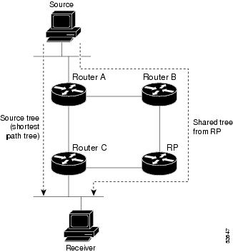
In PIM-SM, the rendezvous point (RP) is used to bridge sources sending data to a particular group with receivers sending joins for that group. In the initial set up of state, interested receivers receive data from senders to the group across a single data distribution tree rooted at the RP. This type of distribution tree is called a shared tree or rendezvous point tree (RPT) as illustrated in Figure 4: Shared Tree and Source Tree (Shortest Path Tree), above. Data from senders is delivered to the RP for distribution to group members joined to the shared tree.
Unless the command is configured, this initial state gives way as soon as traffic is received on the leaf routers (designated router closest to the host receivers). When the leaf router receives traffic from the RP on the RPT, the router initiates a switch to a data distribution tree rooted at the source sending traffic. This type of distribution tree is called a shortest path tree or source tree. By default, the Cisco IOS XR Software switches to a source tree when it receives the first data packet from a source.
-
Receiver joins a group; leaf Router C sends a join message toward RP.
-
RP puts link to Router C in its outgoing interface list.
-
Source sends data; Router A encapsulates data in Register and sends it to RP.
-
RP forwards data down the shared tree to Router C and sends a join message toward Source. At this point, data may arrive twice at the RP, once encapsulated and once natively.
-
When data arrives natively (unencapsulated) at RP, RP sends a register-stop message to Router A.
-
By default, receipt of the first data packet prompts Router C to send a join message toward Source.
-
When Router C receives data on (S,G), it sends a prune message for Source up the shared tree.
-
RP deletes the link to Router C from outgoing interface of (S,G). RP triggers a prune message toward Source.
-
Join and prune messages are sent for sources and RPs. They are sent hop by hop and are processed by each PIM router along the path to the source or RP. Register and register-stop messages are not sent hop by hop. They are exchanged using direct unicast communication between the designated router that is directly connected to a source and the RP for the group.

Note
The spt-threshold infinity command lets you configure the router so that it never switches to the shortest path tree (SPT).
Configuring PIM Parameters
To configure PIM-specific parameters, the router pim configuration mode is used. The default configuration prompt is for IPv4 and will be seen as config-pim-default-ipv4. To ensure the election of a router as PIM DR on a LAN segment, use the dr-priority command. The router with the highest DR priority will win the election. By default, at a preconfigured threshold, the last hop router can join the shortest path tree to receive multicast traffic. To change this behavior, use the command spt-threshold infinity under the router pim configuration mode. This will result in the last hop router permanently joining the shared tree. The frequency at which a router sends PIM hello messages to its neighbors can be configured by the hello-interval command. By default, PIM hello messages are sent once every 30 seconds. If the hello-interval is configured under router pim configuration mode, all the interfaces with PIM enabled will inherit this value. To change the hello interval on the interface, use the hello-interval command under interface configuration mode, as follows:
Configuration Example
Router#configure
Router(config)#router pim
Router(config-pim-default-ipv4)#dr-priority 2
Router(config-pim-default-ipv4)#spt-threshold infinity
Router(config-pim-default-ipv4)#interface TenGigE 0/0/0/1
Router(config-pim-ipv4-if)#dr-priority 4
Router(config-pim-ipv4-if)#hello-interval 45
Router(config-pim-ipv4-if)#commit
Running Configuration
Router#show run router pim
router pim
 address-family ipv4
  dr-priority 2
  spt-threshold infinity
  interface TenGigE0/0/0/1
   dr-priority 4
   hello-interval 45
Verification
Verify if the parameters are set according to the configured values:
Router#show pim interface te0/0/0/1
PIM interfaces in VRF default
Address               Interface                     PIM  Nbr   Hello  DR    DR Count Intvl  Prior
100.1.1.1             TenGigE0/0/0/1                on   1     45     4     this system
Designated Routers
Cisco routers use PIM-SM to forward multicast traffic and follow an election process to select a designated router (DR) when there is more than one router on a LAN segment.
The designated router is responsible for sending PIM register and PIM join and prune messages toward the RP to inform it about host group membership.
If there are multiple PIM-SM routers on a LAN, a designated router must be elected to avoid duplicating multicast traffic for connected hosts. The PIM router with the highest IP address becomes the DR for the LAN unless you choose to force the DR election by use of the dr-priority command. The DR priority option allows you to specify the DR priority of each router on the LAN segment (default priority = 1) so that the router with the highest priority is elected as the DR. If all routers on the LAN segment have the same priority, the highest IP address is again used as the tiebreaker.
Note | DR election process is required only on multi access LANs. The last-hop router directly connected to the host is the DR. |
The figure "Designated Router Election on a Multiaccess Segment", below illustrates what happens on a multi access segment. Router A (10.0.0.253) and Router B (10.0.0.251) are connected to a common multi access Ethernet segment with Host A (10.0.0.1) as an active receiver for Group A. As the Explicit Join model is used, only Router A, operating as the DR, sends joins to the RP to construct the shared tree for Group A. If Router B were also permitted to send (*,G) joins to the RP, parallel paths would be created and Host A would receive duplicate multicast traffic. When Host A begins to source multicast traffic to the group, the DR's responsibility is to send register messages to the RP. Again, if both routers were assigned the responsibility, the RP would receive duplicate multicast packets.
If the DR fails, the PIM-SM provides a way to detect the failure of Router A and to elect a failover DR. If the DR (Router A) were to become inoperable, Router B would detect this situation when its neighbor adjacency with Router A timed out. Because Router B has been hearing IGMP membership reports from Host A, it already has IGMP state for Group A on this interface and immediately sends a join to the RP when it becomes the new DR. This step reestablishes traffic flow down a new branch of the shared tree using Router B. Additionally, if Host A were sourcing traffic, Router B would initiate a new register process immediately after receiving the next multicast packet from Host A. This action would trigger the RP to join the SPT to Host A, using a new branch through Router B.
Note | Two PIM routers are neighbors if there is a direct connection between them. To display your PIM neighbors, use the show pim neighbor command in EXEC mode. |
-
They are not used for unicast routing but are used only by PIM to look up an IPv4 next hop to a PIM source.
-
They are not published to the Forwarding Information Base (FIB).
-
When multicast-intact is enabled on an IGP, all IPv4 destinations that were learned through link-state advertisements are published with a set equal-cost mcast-intact next-hops to the RIB. This attribute applies even when the native next-hops have no IGP shortcuts.
-
In IS-IS, the max-paths limit is applied by counting both the native and mcast-intact next-hops together. (In OSPFv2, the behavior is slightly different.)
Configuration Example
Configures the router to use DR priority 4 for TenGigE interface 0/0/0/1, but other interfaces will inherit DR priority 2:
Router#configure
Router(config)#router pim
Router(config-pim-default-ipv4)#dr-priority 2
Router(config-pim-default-ipv4)#interface TenGigE 0/0/0/1
Router(config-pim-ipv4-if)#dr-priority 4
Router(config-ipv4-acl)#commit
Running Configuration
Router#show run router pim
router pim
 address-family ipv4
  dr-priority 2
  spt-threshold infinity
  interface TenGigE0/0/0/1
   dr-priority 4
   hello-interval 45
Verification
Verify if the parameters are set according to the configured values:
Router#show pim interface
PIM interfaces in VRF default
Address           Interface           PIM  Nbr   Hello  DR    DR Count Intvl  Prior
100.1.1.1        TenGigE0/0/0/1        on   1     45     4     this system
26.1.1.1         TenGigE0/0/0/26       on   1     30     2     this system
Rendezvous Points
When PIM is configured in sparse mode, you must choose one or more routers to operate as a rendezvous point (RP). A rendezvous point is a single common root placed at a chosen point of a shared distribution tree, as illustrated in Figure 4: Shared Tree and Source Tree (Shortest Path Tree). A rendezvous point can be either configured statically in each box or learned through a dynamic mechanism. PIM DRs forward data from directly connected multicast sources to the rendezvous point for distribution down the shared tree. Data is forwarded to the rendezvous point in one of two ways:
-
Encapsulated in register packets and unicast directly to the rendezvous point by the first-hop router operating as the DR.
-
Multicast forwarded by the RPF forwarding algorithm, described in the Reverse-Path Forwarding, if the rendezvous point has itself joined the source tree.
The rendezvous point address is used by first-hop routers to send PIM register messages on behalf of a host sending a packet to the group. The rendezvous point address is also used by last-hop routers to send PIM join and prune messages to the rendezvous point to inform it about group membership. You must configure the rendezvous point address on all routers (including the rendezvous point router).
A PIM router can be a rendezvous point for more than one group. Only one rendezvous point address can be used at a time within a PIM domain. The conditions specified by the access list determine for which groups the router is a rendezvous point.
You can either manually configure a PIM router to function as a rendezvous point or allow the rendezvous point to learn group-to-RP mappings automatically by configuring Auto-RP or BSR.
Static RP
It is possible to statically configure an RP for a multicast group range. The address of the RP must be configured on every router in the domain. Configuring static RPs is relatively easy and can be done with one or two lines of configuration on each router. If the network does not have many different RPs defined and/or they do not change very often, then this could be the simplest method to define RPs. This can also be an attractive option if the network is small.
However this can be a laborious task in a large and complex network. Every router must have the same RP address. This means changing the RP address requires reconfiguring every router. If several RPs are active for different groups, then information regarding which RP is handling which group must be known by all routers. To ensure this information is complete, several configuration commands may be required. If the manually configured RP fails, there is no failover procedure for another router to take over the function performed by the failed RP. This method does not provide any kind of load-balancing. Static RP can be combined with Anycast RP to provide RP load sharing and redundancy.
Static RP can co-exist with dynamic RP mechanisms (ie: Auto-RP). Dynamically learned RP takes precedence over manually configured RPs. If a router receives Auto-RP information for a multicast group that has manually configured RP information, then the Auto-RP information will be used.
Configuring Static RP
Configuration Example
Statically configures the address of a PIM rendezvous point (RP) for a particular group to 2.2.2.2.
Router#configure
Router(config)#router pim
Router(config-pim-default-ipv4)#address-family ipv4
Router(config-pim-default-ipv4)#rp-address 2.2.2.2
*/Use the group-access-list keyword to configure RP for a specific multicast group or a range of multicast groups. If the optional group-access-list-number argument is not specified, the rendezvous point for the group is applied to the entire IP multicast group range (224.0.0.0/4)*/
Router(config-mcast)#commit
Running Configuration
router pim
 address-family ipv4
  rp-address 2.2.2.2
 !
Verification
Verify if the Static RP is 2.2.2.2:
Router#show pim rp mapping
PIM Group-to-RP Mappings
Group(s) 224.0.0.0/4
  RP 2.2.2.2 (?), v2
    Info source: 0.0.0.0 (?), elected via config
      Uptime: 17:46:30, expires: never
Auto RP
-
It is easy to use multiple RPs within a network to serve different group ranges.
-
It allows load splitting among different RPs.
-
It facilitates the arrangement of RPs according to the location of group participants.
-
It avoids inconsistent, manual RP configurations that might cause connectivity problems.
Multiple RPs can be used to serve different group ranges or to serve as hot backups for each other. To ensure that Auto-RP functions, configure routers as candidate RPs so that they can announce their interest in operating as an RP for certain group ranges. Additionally, a router must be designated as an RP-mapping agent that receives the RP-announcement messages from the candidate RPs, and arbitrates conflicts. The RP-mapping agent sends the consistent group-to-RP mappings to all remaining routers. Thus, all routers automatically determine which RP to use for the groups they support. All routers automatically learn the RP information making it easier to administer and update RP information. There is no configuration needed on every router separately (except on candidate RPs and mapping agents). Auto-RP permits back-up RPs to be configured enabling an RP failover mechanism.
If you configure PIM in sparse mode and do not configure Auto-RP, you must statically configure an RP as described in the Configuring a Static RP. When router interfaces are configured in sparse mode, Auto-RP can still be used if all routers are configured with a static RP address for the Auto-RP groups.
Configuring Auto-RP (Candidate RP)
Configuration Example
Sends rendezvous point announcements from all PIM-enabled interfaces for a maximum of 32 hops. The IP address by which the router wants to be identified as a rendezvous point is the IP address associated with the Loopback interface 0. Access list 5 designates the groups that this router serves as the rendezvous point.
Router#configure
Router(config)#router pim
Router(config-pim-default-ipv4)#auto-rp candidate-rp Loopback0 scope 32
*/A router can also advertise itself to be the candidate RP for a specific multicast group or a range of multicast groups.
This is configured by using the group-list access-list-name keyword./*
Router(config-pim-default-ipv4)#commit
Running Configuration
Router#show run router pim
router pim
 address-family ipv4
  auto-rp candidate-rp Loopback0 scope 32 group-list 224-4 interval 60
Verification
Router #show run int loopback 0
interface Loopback0
 ipv4 address 1.1.1.1 255.255.255.255

*/Verify if the candidate RP is configured for the loopback 0 interface with IP address-1.1.1.1/*:
Router#show auto-rp candidate-rp
ACL Name        Group Range        Mode   Candidate RP    TTL   Interval
               	 224.0.0.0/4        SM     	1.1.1.1         	32    	60

*/Displays the elected RP through auto-RP/*:
Router#show pim rp mapping
PIM Group-to-RP Mappings
Group(s) 224.0.0.0/4
  RP 1.1.1.1 (?), v2
    Info source: 1.1.1.1 (?), elected via autorp
      Uptime: 20:49:32, expires: 00:02:30
Configuring Auto-RP (Mapping-Agent)
Configuration Example
Configures the router to function as the mapping-agent. The interface from which the mapping agent messages are sourced is Loopback0.
Router#configure
Router(config)#router pim
Router(config-pim-default-ipv4)#auto-rp mapping-agent Loopback0 scope 32
Router(config-pim-default-ipv4)#commit
Running Configuration
Router#show run router pim
router pim
 address-family ipv4
  auto-rp mapping-agent Loopback0 scope 32 interval 60
Verification
Router#show run int loopback 0
interface Loopback0
 ipv4 address 1.1.1.1 255.255.255.255

*/Verify if the loopback0 interface is configured as the mapping agent/*:
Router#show auto-rp mapping-agent
Mapping Agent Table
  Maximum number of mapping cache entries 500
  Current number of mapping cache entries 1
1.1.1.1 (expire : 140 secs)
  224.0.0.0/4  SM

*/Displays the mapping agent elected through auto-RP/*:
Router#show pim rp mapping
PIM Group-to-RP Mappings
Group(s) 224.0.0.0/4
  RP 1.1.1.1 (?), v2
    Info source: 1.1.1.1 (?), elected via autorp
      Uptime: 20:49:32, expires: 00:02:30
PIM Bootstrap Router
The PIM bootstrap router (BSR) provides a fault-tolerant, automated RP discovery and distribution mechanism that simplifies the Auto-RP process. This feature is enabled by default allowing routers to dynamically learn the group-to-RP mappings.
PIM uses the BSR to discover and announce RP-set information for each group prefix to all the routers in a PIM domain. This is the same function accomplished by Auto-RP, but the BSR is part of the PIM specification. The BSR mechanism interoperates with Auto-RP on Cisco routers.
To avoid a single point of failure, you can configure several candidate BSRs in a PIM domain. A BSR is elected among the candidate BSRs automatically.
Candidates use bootstrap messages to discover which BSR has the highest priority. The candidate with the highest priority sends an announcement to all PIM routers in the PIM domain that it is the BSR.
Routers that are configured as candidate RPs unicast to the BSR the group range for which they are responsible. The BSR includes this information in its bootstrap messages and disseminates it to all PIM routers in the domain. Based on this information, all routers are able to map multicast groups to specific RPs. As long as a router is receiving the bootstrap message, it has a current RP map.
Configuring PIM Bootstrap Router
Configuration Example
Configures the router as a candidate BSR with a hash mask length of 30:
Router#config
Router(config)#router pim
Router(config-pim-default-ipv4)#bsr candidate-bsr 1.1.1.1 hash-mask-len 30
Router(config-pim-default-ipv4-if)#commit
Configures the router to advertise itself as a candidate rendezvous point to the BSR in its PIM domain. Access list number 4 specifies the prefix associated with the candidate rendezvous point address 1.1.1.1 . This rendezvous point is responsible for the groups with the prefix 239.
Router#config
Router(config)#router pim
Router(config-pim-default-ipv4)#bsr candidate-rp 1.1.1.1 group-list 4
Router(config-pim-default-ipv4)#exit
Router(config)#ipv4 access-list 4
Router(config-ipv4-acl)#permit ipv4 any 239.0.0.0 0.255.255.255
Router(config-ipv4-acl)#commit
Running Configuration
Router#show run router pim
router pim
 address-family ipv4
  bsr candidate-bsr 1.1.1.1 hash-mask-len 30 priority 1
  bsr candidate-rp 1.1.1.1 group-list 4 priority 192 interval 60
Verification
Router#show pim rp mapping
PIM Group-to-RP Mappings
Group(s) 239.0.0.0/8
  RP 1.1.1.1 (?), v2
    Info source: 1.1.1.1 (?), elected via bsr, priority 192, holdtime 150
      Uptime: 00:02:50, expires: 00:01:54

Router#show pim bsr candidate-rp
PIM BSR Candidate RP Info
Cand-RP          mode  scope priority uptime    group-list
1.1.1.1         	 BD    16      192       00:04:06    4

Router#show pim bsr election
PIM BSR Election State
Cand/Elect-State           Uptime   BS-Timer     BSR                                   C-BSR
Elected/Accept-Pref     00:03:49 00:00:25 1.1.1.1 [1, 30]          1.1.1.1 [1, 30]
PIM-Source Specific Multicast
When PIM-SM is used with SSM, multi-cast routing is easier to manage. This is because RPs (rendezvous points) are not required and therefore, no shared trees (*,G) are built.
There is no specific IETF document defining PIM-SSM. However, RFC4607 defines the overall SSM behavior.
In the rest of this document, we use the term PIM-SSM to describe PIM behavior and configuration when SSM is used.
- By default, PIM-SSM operates in the 232.0.0.0/8 multicast group range for IPv4. To configure these values, use the ssm range command.
-
If SSM is deployed in a network already configured for PIM-SM, only the last-hop routers must be upgraded with Cisco IOS XR Software that supports the SSM feature.
-
No MSDP SA messages within the SSM range are accepted, generated, or forwarded.
-
SSM can be disabled using the ssm disable command.
-
The ssm allow-override command allows SSM ranges to be overridden by more specific ranges.
In many multicast deployments where the source is known, protocol-independent multicast-source-specific multicast (PIM-SSM) mapping is the obvious multicast routing protocol choice to use because of its simplicity. Typical multicast deployments that benefit from PIM-SSM consist of entertainment-type solutions like the ETTH space, or financial deployments that completely rely on static forwarding.
In SSM, delivery of data grams is based on (S,G) channels. Traffic for one (S,G) channel consists of datagrams with an IP unicast source address S and the multicast group address G as the IP destination address. Systems receive traffic by becoming members of the (S,G) channel. Signaling is not required, but receivers must subscribe or unsubscribe to (S,G) channels to receive or not receive traffic from specific sources. Channel subscription signaling uses IGMP to include mode membership reports, which are supported only in Version 3 of IGMP (IGMPv3).
To run SSM with IGMPv3, SSM must be supported on the multicast router, the host where the application is running, and the application itself. Cisco IOS XR Software allows SSM configuration for an arbitrary subset of the IP multicast address range 224.0.0.0 through 239.255.255.255.
When an SSM range is defined, existing IP multicast receiver applications do not receive any traffic when they try to use addresses in the SSM range, unless the application is modified to use explicit (S,G) channel subscription.
Benefits of PIM-SSM over PIM-SM
PIM-SSM is derived from PIM-SM. However, whereas PIM-SM allows for the data transmission of all sources sending to a particular group in response to PIM join messages, the SSM feature forwards traffic to receivers only from those sources that the receivers have explicitly joined. Because PIM joins and prunes are sent directly towards the source sending traffic, an RP and shared trees are unnecessary and are disallowed. SSM is used to optimize bandwidth utilization and deny unwanted Internet broad cast traffic. The source is provided by interested receivers through IGMPv3 membership reports.
Configuring PIM-SSM
Configuration Example
Configures SSM service for the IP address range defined by access list 4.
Router#config
Router (config)#ipv4 access-list 4
Router(config-ipv4-acl)#permit ipv4 any 224.2.151.0 0.0.0.255
Router(config-ipv4-acl)#exit
Router(config)#multicast-routing
Router(config-mcast)#address-family ipv4
Router(config-mcast-default-ipv4)#ssm range 4
Router(config-mcast-default-ipv4)#commit
Router(config-mcast-default-ipv4)#end
Running Configuration
Router#show run multicast-routing
multicast-routing
 address-family ipv4
  ssm range 4
  interface all enable
 !
Verification
Verify if the SSM range is configured according to the set parameters:
Router#show access-lists 4
ipv4 access-list 4
 10 permit ipv4 any 224.2.151.0 0.0.0.255

*/Verify if the SSM is configured for 224.2.151.0/24/*:

Router#show pim group-map
IP PIM Group Mapping Table
(* indicates group mappings being used)
(+ indicates BSR group mappings active in MRIB)
Group Range         Proto Client   Groups RP address      Info
224.0.1.39/32*      DM    perm     1      0.0.0.0
224.0.1.40/32*      DM    perm     1      0.0.0.0
224.0.0.0/24*       NO    perm     0      0.0.0.0
224.2.151.0/24*     SSM   config   0      0.0.0.0
224.2.151.0/24      SM    bsr      0      1.1.1.1         RPF: Null,0.0.0.0
224.0.0.0/4*        SM    static   4000   0.0.0.0         RPF: Null,0.0.0.0
Configuring PIM Per Interface States Limit
The PIM Per Interface States Limit sets a limit on creating OIF for the PIM interface. When the set limit is reached, the group is not accounted against this interface but the group can exist in PIM context for some other interface.
The following configuration sets a limit on the number of routes for which the given interface may be an outgoing interface as a result of receiving a PIM J/P message.
-
If a user has configured a maximum of 20 groups and has reached the maximum number of groups, then no more groups/OIFs can be created. If the user now decreases the maximum number to 10, the 20 joins/OIF will remain and a message of reaching the max is displayed. No more joins/OIF can be added at this point until it has reached less than 10.
-
If a user already has configured a maximum of 30 joins/OIFs and add a max of 20, the configuration occurs displaying a message that the max has been reached. No states will change but no more joins/OIFs can happen until the number is brought down below the maximum number of groups.
-
Local interest joins are added, even if the limit has reached and is accounted for it.
Configuration Example
Sets a limit on the number of routes to 5000 for which the given interface may be an outgoing interface as a result of receiving a PIM J/P message.
Router#config
Router(config)#router pim
Router(config-igmp)#maximum groups-per-interface 5000
Router(config-igmp)#commit
Running Configuration
Router#show run router pim
router pim
 address-family ipv4
  maximum routes 5000
  maximum route-interfaces 7000
  interface TenGigE0/0/0/6
   maximum route-interfaces 6000
Verification
Verify if the configuration matches the set values:
Router#show pim summary
PIM Summary for VRF:default
PIM State Counters
                             Current        Maximum        Warning-threshold
Routes                     	 4003           5000          		 5000
Topology Interface States  	 5037           7000       		    7000
SM Registers                	0              20000         		 20000
Auto RP Group Ranges         0              500          		  450
BSR Group Ranges            	1              500           		 450
BSR C-RP caches             	1              100            		100
Internet Group Management Protocol
Cisco IOS XR Software provides support for Internet Group Management Protocol (IGMP) over IPv4.
IGMP provides a means for hosts to indicate which multicast traffic they are interested in and for routers to control and limit the flow of multicast traffic throughout the network. Routers build state by means of IGMP messages; that is, router queries and host reports.
A set of routers and hosts that receive multicast data streams from the same source is called a multicast group. Hosts use IGMP messages to join and leave multicast groups.
Note | IGMP messages use group addresses, which are Class D IP addresses. The high-order four bits of a Class D address are 1110. Host group addresses can be in the range 224.0.0.0 to 239.255.255.255. The address 224.0.0.0 is guaranteed not to be assigned to any group. The address 224.0.0.1 is assigned to all systems on a subnet. The address 224.0.0.2 is assigned to all routers on a subnet. |
IGMP Versions
- IGMP Version 1 provides for the basic query-response mechanism that allows the multicast router to determine which multicast groups are active and for other processes that enable hosts to join and leave a multicast group.
-
IGMP Version 2 extends IGMP allowing such features as the IGMP query timeout and the maximum query-response time. See RFC 2236.
- IGMP Version 3 permits joins and leaves for certain source and group pairs instead of requesting traffic from all sources in the multicast group.
Functioning of IGMP Routing
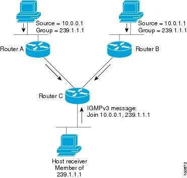
The following image "IGMP Singaling" , illustrates two sources, 10.0.0.1 and 10.0.1.1, that are multicasting to group 239.1.1.1.
The receiver wants to receive traffic addressed to group 239.1.1.1 from source 10.0.0.1 but not from source 10.0.1.1.
The host must send an IGMPv3 message containing a list of sources and groups (S, G) that it wants to join and a list of sources and groups (S, G) that it wants to leave. Router C can now use this information to prune traffic from Source 10.0.1.1 so that only Source 10.0.0.1 traffic is being delivered to Router C.
Note | When configuring IGMP, ensure that all systems on the subnet support the same IGMP version. The router does not automatically detect Version 1 systems. |
By default, Cisco IOS XR supports IGMPv3; however, the IGMP version can be changed through the CLI. IGMPv3 provides backward compatibility with IGMPv2. When an IOS XR router with a default setting of IGMPv3 receives an IGMPv2 report, it turns on the old host compatibility mode and treats the report as (*,G) EXCLUDE {none}. This indicates that IGMPv3 filters do not exclude any source from sending traffic to this multicast group.
Configuring IGMP Routing
Configuration Example
Changes the IGMP version of the router to version 2.
Router#config
Router(config)#router igmp
Router(config-igmp)#version 2
Router(config-igmp)#interface TenGigE 0/0/0/1
Router(config-igmp-default-if)#static-group 225.2.2.2 inc-mask 0.0.0.2 count 2 1.1.1.1
*/ The inc-mask keyword specifies a mask for the increment range.
This mask is used with the group address to generate subsequent group addresses/*
Router(config-igmp-default-if)#query-interval 120
Router(config-igmp-default-if)#commit
Note | In this example, the router is configured to support static joins. The router is configured to statically join two multicast groups 225.2.2.2 and 225.2.2.4 for the specific source 1.1.1.1 and sets the query interval to 120 seconds. |
Running Configuration
Router#show run router igmp
router igmp
 interface TenGigE0/0/0/1
  static-group 225.2.2.2 inc-mask 0.0.0.2 count 2 1.1.1.1
 !
 version 2
!
Verification
Verify if the version and the query interval matches the configured values:
Router#show igmp interface te0/0/0/1
TenGigE0/0/0/1 is up, line protocol is up
  Internet address is 100.1.1.1/24
  IGMP is enabled on interface
  Current IGMP version is 2
  IGMP query interval is 120 seconds
  IGMP querier timeout is 245 seconds
  IGMP max query response time is 10 seconds
  Last member query response interval is 1 seconds
  IGMP activity: 12 joins, 5 leaves
  IGMP querying router is 100.1.1.1 (this system)
  Time elapsed since last query sent 00:00:11
  Time elapsed since IGMP router enabled 20:36:41
 Time elapsed since last report received 00:00:01
Verify if the static groups are programmed correctly in the MRIB database:
Router#show mrib route 225.2.2.2
Verify if the static groups are programmed correctly in the MRIB database:
Router# show mrib route 225.2.2.2
IP Multicast Routing Information Base
Entry flags: L - Domain-Local Source, E - External Source to the Domain,
    C - Directly-Connected Check, S - Signal, IA - Inherit Accept,
    IF - Inherit From, D - Drop, ME - MDT Encap, EID - Encap ID,
    MD - MDT Decap, MT - MDT Threshold Crossed, MH - MDT interface handle
    CD - Conditional Decap, MPLS - MPLS Decap, EX – Extranet
    MoFE - MoFRR Enabled, MoFS - MoFRR State, MoFP - MoFRR Primary
    MoFB - MoFRR Backup, RPFID - RPF ID Set, X – VXLAN
Interface flags: F - Forward, A - Accept, IC - Internal Copy,
    NS - Negate Signal, DP - Don't Preserve, SP - Signal Present,
    II - Internal Interest, ID - Internal Disinterest, LI - Local Interest,
    LD - Local Disinterest, DI - Decapsulation Interface
    EI - Encapsulation Interface, MI - MDT Interface, LVIF - MPLS Encap,
    EX - Extranet, A2 - Secondary Accept, MT - MDT Threshold Crossed,
    MA - Data MDT Assigned, LMI - mLDP MDT Interface, TMI - P2MP-TE MDT Interface
    IRMI - IR MDT Interface
(*,225.2.2.2) RPF nbr: 30.40.1.2 Flags: C RPF
  Up: 00:02:12
  Incoming Interface List
    TenGigE0/0/0/18 Flags: A NS, Up: 00:02:12
  Outgoing Interface List
    TenGigE0/0/0/1 Flags: F NS LI, Up: 00:02:12
Configuring IGMP Per Interface States Limit
The IGMP Per Interface States Limit sets a limit on creating OIF for the IGMP interface. When the set limit is reached, the group is not accounted against this interface but the group can exist in IGMP context for some other interface.
Restrictions
- If a user has configured a maximum of 20 groups and has reached the maximum number of groups, then no more groups can be created. If the user reduces the maximum number of groups to 10, the 20 joins will remain and a message of reaching the maximum is displayed. No more joins can be added until the number of groups has reached less than 10.
- If a user already has configured a maximum of 30 joins and add a max of 20, the configuration occurs displaying a message that the maximum has been reached. No state change occurs and also no more joins can occur until the threshold number of groups is brought down below the maximum number of groups.
Configuration Example
Configures all interfaces with 4000 maximum groups per interface except TenGigE interface 0/0/0/6, which is set to 3000:
Router#config
Router(config)#router pim
Router(config-igmp)#maximum groups-per-interface 4000
Router(config-igmp)#interface TenGigE 0/0/0/6
Router(config-igmp-default-if)#maximum groups-per-interface 3000
Router(config-igmp-default-if)#commit
Running Configuration
router igmp
 interface TenGigE0/0/0/6
  maximum groups-per-interface 3000
 !
 maximum groups-per-interface 4000
!
Verification
Router#show igmp summary
Robustness Value 2
No. of Group x Interfaces 37
Maximum number of Group x Interfaces 50000
Supported Interfaces   : 9
Unsupported Interfaces: 0
Enabled Interfaces     : 8
Disabled Interfaces    : 1
MTE tuple count        : 0
Interface                      Number  Max #
                               Groups  Groups
Loopback0                       4       4000
TenGigE0/0/0/0                  5       4000
TenGigE0/0/0/1                  5       4000
TenGigE0/0/0/2                  0       4000
TenGigE0/0/0/3                  5       4000
TenGigE0/0/0/6                  5       3000
TenGigE0/0/0/18                 5       4000
TenGigE0/0/0/19                 5       4000
TenGigE0/0/0/6.1                3       4000
DNS-based SSM Mapping
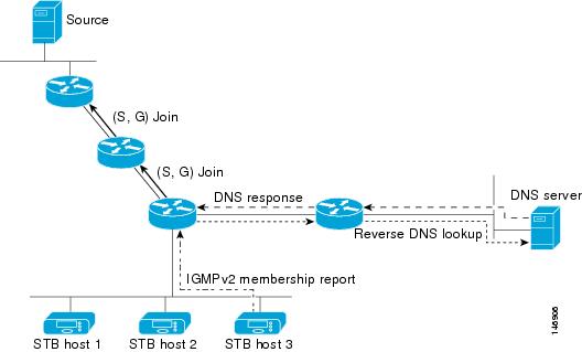
DNS-based SSM mapping enables you to configure the last hop router to perform a reverse DNS lookup to determine sources sending to groups (see the figure below). When DNS-based SSM mapping is configured, the router constructs a domain name that includes the group address G and performs a reverse lookup into the DNS. The router looks up IP address resource records (IP A RRs) to be returned for this constructed domain name and uses the returned IP addresses as the source addresses associated with this group. SSM mapping supports up to 20 sources for each group. The router joins all sources configured for a group.
The SSM mapping mechanism that enables the last hop router to join multiple sources for a group can be used to provide source redundancy for a TV broadcast. In this context, the redundancy is provided by the last hop router using SSM mapping to join two video sources simultaneously for the same TV channel. However, to prevent the last hop router from duplicating the video traffic, it is necessary that the video sources utilize a server-side switchover mechanism where one video source is active while the other backup video source is passive. The passive source waits until an active source failure is detected before sending the video traffic for the TV channel. The server-side switchover mechanism, thus, ensures that only one of the servers is actively sending the video traffic for the TV channel.
|
G4.G3.G2.G1 [multicast-domain] [timeout] |
IN A source-address-1 |
|
|
IN A source-address-2 |
|
|
IN A source-address-n |
The multicast-domain argument is a configurable DNS prefix. The default DNS prefix is in-addr.arpa. You should only use the default prefix when your installation is either separate from the internet or if the group names that you map are global scope group addresses (RFC 2770 type addresses that you configure for SSM) that you own.
Note | See your DNS server documentation for more information about configuring DNS RRs. |
To configure DNS-based SSM mapping in the software, you must configure a few global commands but no per-channel specific configuration is needed. There is no change to the configuration for SSM mapping if additional channels are added. When DNS-based SSM mapping is configured, the mappings are handled entirely by one or more DNS servers. All DNS techniques for configuration and redundancy management can be applied to the entries needed for DNS-based SSM mapping. Enable IP multicast routing, enable PIM sparse mode, and configure SSM before performing this task. Before you can configure and use SSM mapping with DNS lookups, you need to be able to add records to a running DNS server. If you do not already have a DNS server running, you need to install one. The Cisco IOS XR software does not provide for DNS server functionality.
Configuring DNS-based SSM Mapping
Configuration Example
Enables DNS-based ssm mapping and configures the last hop router to perform DNS look-ups to learn the IP addresses of sources sending to a group.
Router#config
Router(config)#domain multicast cisco.com
Router(config-igmp)#domain name-server 10.10.10.1
Router(config-igmp)#router igmp
Router(config-igmp)#ssm map query dns
Router(config-igmp)#commit
Static Group to Source Mapping (IGMP V2 to IGMP V3)
Configure a source (1.1.1.1) as part of a set of sources that map SSM groups described by the specified access-list (4).
Configuration Example
Router#configure
Router(config)#ipv4 access-list 4
Router(config-ipv4-acl)#permit ipv4 any 229.1.1.0 0.0.0.255
Router(config-ipv4-acl)#exit
Router(config)# multicast-routing
Router(config-mcast)#address-family ipv4
Router(config-mcast-default-ipv4)#ssm range 4
Router(config-mcast-default-ipv4)#exit
Router(config-mcast)#exit
Router(config)#router igmp
Router(config-igmp)#ssm map static 1.1.1.1 4
*/Repeat the above step as many times as you have source addresses to include in the set for SSM mapping/*
Router(config-igmp)#int te0/0/0/3
Router(config-igmp-default-if)#static-group 229.1.1.1
Router(config-igmp-default-if)#commit
Running Configuration
Router#show run multicast-routing
multicast-routing
 address-family ipv4
  ssm range 4
  interface all enable
 !
!
Router#show access-lists 4
ipv4 access-list 4
 10 permit ipv4 any 229.1.1.0 0.0.0.255
RP/0/RP0/CPU0:INB#sh run router igmp
Mon Apr 25 15:27:23.471 UTC
router igmp
 interface TenGigE0/0/0/3
  static-group 229.1.1.1
 !
 ssm map static 1.1.1.1 4
Verification
Verify if the parameters are set according to the configured values:
Router#show mrib route 229.1.1.1
IP Multicast Routing Information Base
Entry flags: L - Domain-Local Source, E - External Source to the Domain,
    C - Directly-Connected Check, S - Signal, IA - Inherit Accept,
    IF - Inherit From, D - Drop, ME - MDT Encap, EID - Encap ID,
    MD - MDT Decap, MT - MDT Threshold Crossed, MH - MDT interface handle
    CD - Conditional Decap, MPLS - MPLS Decap, EX - Extranet
    MoFE - MoFRR Enabled, MoFS - MoFRR State, MoFP - MoFRR Primary
    MoFB - MoFRR Backup, RPFID - RPF ID Set, X - VXLAN
Interface flags: F - Forward, A - Accept, IC - Internal Copy,
    NS - Negate Signal, DP - Don't Preserve, SP - Signal Present,
    II - Internal Interest, ID - Internal Disinterest, LI - Local Interest,
    LD - Local Disinterest, DI - Decapsulation Interface
    EI - Encapsulation Interface, MI - MDT Interface, LVIF - MPLS Encap,
    EX - Extranet, A2 - Secondary Accept, MT - MDT Threshold Crossed,
    MA - Data MDT Assigned, LMI - mLDP MDT Interface, TMI - P2MP-TE MDT Interface
    IRMI - IR MDT Interface
(1.1.1.1,229.1.1.1) RPF nbr: 1.1.1.1 Flags: RPF
  Up: 00:01:11
  Incoming Interface List
    Loopback0 Flags: A, Up: 00:01:11
  Outgoing Interface List
    TenGigE0/0/0/3 Flags: F NS LI, Up: 00:01:11
Multicast Nonstop Forwarding
Nonstop forwarding (NSF) feature for multicast packet forwarding helps alleviating network failures, or software upgrades and downgrades. Although it is recommended to use the NSF lifetime default values, it is possible to modify the NSF timeout values for Protocol Independent Multicast (PIM) and Internet Group Management Protocol (IGMP). Use these commands when PIM and IGMP are configured with nondefault interval or query intervals for join and prune operations.
Generally, configure the IGMP NSF and PIM NSF lifetime values to equal or exceed the query or join query interval. For example, if you set the IGMP query interval to 120 seconds, set the IGMP NSF lifetime to 120 seconds (or greater). If the Cisco IOS XR Software control plane does not converge and reconnect after NSF is enabled on your router, multicast packet forwarding continues for up to 15 minutes, then packet forwarding stops.
For NSF to operate in your multicast network, you must also enable NSF for the unicast protocols (such as IS-IS, OSPF, and BGP) that PIM relies on for Reverse Path Forwarding (RPF) information.
Configuration Example
Configures the NSF timeout value to 30 seconds for multicast forwarding route entries under the PIM and IGMP processes.
Router#configure
Router(config)#router igmp
Router(config-igmp)#nsf lifetime 30
Router(config-igmp)#commit
Router(config-igmp)#router pim
Router(config-pim)#address-family ipv4
Router(config-pim-default-ipv4)#nsf lifetime 30
*/If you configure the PIM hello interval to a nondefault value, configure the PIM NSF lifetime to a value less than the hello
hold time. Typically, the value of the hold-time field is 3.5 times the interval time value, or 120 seconds if the PIM hello
interval time is 30 seconds/*.
Router(config-pim-default-ipv4)#commit
Running Configuration
Router#show run router igmp
router igmp
 nsf lifetime 30
!
Router#show run router pim
router pim
 address-family ipv4
  rp-address 3.3.3.3
  nsf lifetime 30
 !
Verification
Verify if the parameters are set according to the configured values:
Router#show pim nsf detail
IP PIM Non-Stop Forwarding Status:
Multicast routing state: Normal
   NSF Lifetime:       00:00:30
   Last NSF On triggered: Thu Apr 21 15:37:43 2016, 4d00h
   Last NSF Off triggered: Thu Apr 21 15:37:43 2016, 4d00h
   Last NSF ICD Notification received: never, never
   Respawn Count: 1

Router#show igmp nsf detail
IGMP Non-Stop Forwarding Status:
Multicast routing state: Normal
   NSF Lifetime:       00:00:30
   Last NSF On triggered: Thu Apr 21 15:37:47 2016, 4d00h
   Last NSF Off triggered: Thu Apr 21 15:37:47 2016, 4d00h
   Last NSF ICD Notification received: never, never
   Respawn Count: 1
Use Case: Video Streaming
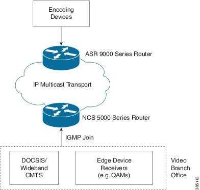
In today's broadcast video networks, proprietary transport systems are used to deliver entire channel line-ups to each video branch office. IP based transport network would be a cost efficient/convenient alternative to deliver video services combined with the delivery of other IP based services. (Internet delivery or business services)
By its very nature, broadcast video is a service well-suited to using IP multicast as a more efficient delivery mechanism to reach end customers.
-
Encoding devices in digital master headends, encode one or more video channels into a Moving Pictures Expert Group (MPEG) stream which is carried in the network via IP multicast.
-
Devices at video branch office are configured by the operator to request the desired multicast content via IGMP joins.
-
The network, using PIM-SM as its multicast routing protocol, routes the multicast stream from the digital master headend to edge device receivers located in the video branch office. These edge devices could be edge QAM devices which modulate the MPEG stream for an RF frequency, or CMTS for DOCSIS.
Video Streaming
 Feedback