-
- Configuring Frame Relay
- Frame Relay 64-Bit Counters
- Frame Relay Queueing and Fragmentation at the Interface
- Frame Relay PVC Bundles with QoS Support for IP and MPLS
- Frame Relay PVC Interface Priority Queueing
- Frame Relay IP RTP Priority
- PPP over Frame Relay
- Multilink Frame Relay (FRF.16.1)
- Distributed Multilink Frame Relay (FRF.16)
- Layer 2 Tunneling Protocol Version 3
- Configuring SMDS
- L2VPN Pseudowire Redundancy
- L2VPN Interworking
- Layer 2 Local Switching
Cisco IOS Wide-Area Networking Configuration Guide, Release 12.2SR
Bias-Free Language
The documentation set for this product strives to use bias-free language. For the purposes of this documentation set, bias-free is defined as language that does not imply discrimination based on age, disability, gender, racial identity, ethnic identity, sexual orientation, socioeconomic status, and intersectionality. Exceptions may be present in the documentation due to language that is hardcoded in the user interfaces of the product software, language used based on RFP documentation, or language that is used by a referenced third-party product. Learn more about how Cisco is using Inclusive Language.
- Updated:
- February 6, 2008
Chapter: Layer 2 Local Switching
- Finding Feature Information
- Contents
- Prerequisites for Layer 2 Local Switching
- Restrictions for Layer 2 Local Switching
- Information About Layer 2 Local Switching
- Configuring ATM-to-ATM PVC Local Switching and Same-Port Switching
- Configuring ATM-to-ATM PVP Local Switching
- Configuring ATM PVP Same-Port Switching
- Configuring ATM-to-Ethernet Port Mode Local Switching
- Configuring ATM-to-Ethernet VLAN Mode Local Switching
- Configuring Ethernet VLAN Same-Port Switching
- Configuring Ethernet Port Mode to Ethernet VLAN Local Switching
- Configuring ATM-to-Frame Relay Local Switching
- Configuring Frame Relay-to-Frame Relay Local Switching
- Configuring Frame Relay Same-Port Switching
- Configuring HDLC Local Switching
- Configuring ACR for ATM-to-ATM Local Switching
- Configuring CEM-to-CEM ACR Local Switching
- Verifying Layer 2 Local Switching
- Example: ATM-to-ATM Local Switching
- Example: ATM PVC Same-Port Switching
- Example: ATM PVP Same-Port Switching
- Example: ATM-to-Ethernet Local Switching
- Example: Ethernet VLAN Same-Port Switching
- Example: ATM-to-Frame Relay Local Switching
- Example: Frame Relay-to-Frame Relay Local Switching
- Example: Frame Relay DLCI Same-Port Switching
- Example: HDLC Local Switching
- Example: NSF SSO: Ethernet Port Mode to Ethernet VLAN Local Switching
Layer 2 Local Switching
The Layer 2 Local Switching feature allows you to switch Layer 2 data in two ways:
•![]() Between two interfaces on the same router
Between two interfaces on the same router
•![]() Between two circuits on the same interface port, which is called same-port switching
Between two circuits on the same interface port, which is called same-port switching
The interface-to-interface switching combinations supported by this feature are:
•![]() ATM to ATM
ATM to ATM
•![]() ATM to Ethernet
ATM to Ethernet
•![]() ATM to Frame Relay
ATM to Frame Relay
•![]() Ethernet to Ethernet VLAN
Ethernet to Ethernet VLAN
•![]() Frame Relay to Frame Relay (and Multilink Frame Relay in Cisco IOS Release 12.0(28)S and later)
Frame Relay to Frame Relay (and Multilink Frame Relay in Cisco IOS Release 12.0(28)S and later)
•![]() High-Level Data Link Control (HDLC)
High-Level Data Link Control (HDLC)
The following same-port switching features are supported:
•![]() ATM Permanent Virtual Circuit (PVC) and Permanent Virtual Path (PVP)
ATM Permanent Virtual Circuit (PVC) and Permanent Virtual Path (PVP)
•![]() Ethernet VLAN
Ethernet VLAN
•![]() Frame Relay
Frame Relay
Finding Feature Information
Your software release may not support all the features documented in this module. For the latest feature information and caveats, see the release notes for your platform and software release. To find information about the features documented in this module, and to see a list of the releases in which each feature is supported, see the "Feature Information for Layer 2 Local Switching" section.
Use Cisco Feature Navigator to find information about platform support and Cisco software image support. To access Cisco Feature Navigator, go to http://www.cisco.com/go/cfn. An account on Cisco.com is not required.
Contents
•![]() Prerequisites for Layer 2 Local Switching
Prerequisites for Layer 2 Local Switching
•![]() Restrictions for Layer 2 Local Switching
Restrictions for Layer 2 Local Switching
•![]() Information About Layer 2 Local Switching
Information About Layer 2 Local Switching
•![]() How to Configure Layer 2 Local Switching
How to Configure Layer 2 Local Switching
•![]() Configuration Examples for Layer 2 Local Switching
Configuration Examples for Layer 2 Local Switching
•![]() Feature Information for Layer 2 Local Switching
Feature Information for Layer 2 Local Switching
Prerequisites for Layer 2 Local Switching
•![]() You must enable Cisco Express Forwarding for the Cisco 7200 series router. You must use Cisco Express Forwarding or Distributed Cisco Express Forwarding for the Cisco 7500 series router. (Distributed Cisco Express Forwarding is enabled already by default on the Gigabit Switch Router [GSR]).
You must enable Cisco Express Forwarding for the Cisco 7200 series router. You must use Cisco Express Forwarding or Distributed Cisco Express Forwarding for the Cisco 7500 series router. (Distributed Cisco Express Forwarding is enabled already by default on the Gigabit Switch Router [GSR]).
•![]() For Frame Relay local switching, you must globally issue the frame-relay switching command.
For Frame Relay local switching, you must globally issue the frame-relay switching command.
Restrictions for Layer 2 Local Switching
•![]() Cisco 7200 and 7500 Series Router Restrictions
Cisco 7200 and 7500 Series Router Restrictions
•![]() Cisco 7600 and 6500 Series Router Restrictions
Cisco 7600 and 6500 Series Router Restrictions
•![]() Cisco 7600 and 6500 Series Router Restrictions
Cisco 7600 and 6500 Series Router Restrictions
•![]() Cisco 10000 Series Router Restrictions
Cisco 10000 Series Router Restrictions
•![]() Gigabit Switch Router Restrictions
Gigabit Switch Router Restrictions
Cisco 7200 and 7500 Series Router Restrictions
•![]() In ATM single cell relay AAL0, the ATM virtual path identifier/virtual channel identifier (VPI/VCI) values must match between the ingress and egress ATM interfaces on the Cisco 7200 series and 7500 series routers. If Layer 2 local switching is desired between two ATM VPIs and VCIs whose values do not match and are on two different interfaces, choose ATM AAL5. However, if the ATM AAL5 is using Operation, Administration, and Maintenance (OAM) transparent mode, the VPI and VCI values must match.
In ATM single cell relay AAL0, the ATM virtual path identifier/virtual channel identifier (VPI/VCI) values must match between the ingress and egress ATM interfaces on the Cisco 7200 series and 7500 series routers. If Layer 2 local switching is desired between two ATM VPIs and VCIs whose values do not match and are on two different interfaces, choose ATM AAL5. However, if the ATM AAL5 is using Operation, Administration, and Maintenance (OAM) transparent mode, the VPI and VCI values must match.
•![]() NSF/SSO: Layer 2 local switching is supported on Cisco 7500 series routers.
NSF/SSO: Layer 2 local switching is supported on Cisco 7500 series routers.
Layer 2 local switching is supported on the following interface processors in the Cisco 7200 series routers:
•![]() C7200-I/O-2FE
C7200-I/O-2FE
•![]() C7200-I/O-GE+E (Only the Gigabit Ethernet port of this port adapter is supported.)
C7200-I/O-GE+E (Only the Gigabit Ethernet port of this port adapter is supported.)
•![]() C7200-I/O-FE
C7200-I/O-FE
Layer 2 local switching is supported on the following interface processors in the Cisco 7500 series routers:
•![]() GEIP (Gigabit Ethernet interface processor)
GEIP (Gigabit Ethernet interface processor)
•![]() GEIP+ (enhanced Gigabit Ethernet interface processor)
GEIP+ (enhanced Gigabit Ethernet interface processor)
Layer 2 local switching is supported on the following port adapters in the Cisco 7200 and 7500 series routers:
•![]() PA-FE-TX (single-port Fast Ethernet 100BASE-TX)
PA-FE-TX (single-port Fast Ethernet 100BASE-TX)
•![]() PA-FE-FX (single-port Fast Ethernet 100BASE-FX)
PA-FE-FX (single-port Fast Ethernet 100BASE-FX)
•![]() PA-2FE-TX (dual-port Fast Ethernet 100BASE-TX)
PA-2FE-TX (dual-port Fast Ethernet 100BASE-TX)
•![]() PA-2FE-FX (dual-port Fast Ethernet 100BASE-FX)
PA-2FE-FX (dual-port Fast Ethernet 100BASE-FX)
•![]() PA-4E (4-port Ethernet adapter)
PA-4E (4-port Ethernet adapter)
•![]() PA-8E (8-port Ethernet adapter)
PA-8E (8-port Ethernet adapter)
•![]() PA-4T (4-port synchronous serial port adapter)
PA-4T (4-port synchronous serial port adapter)
•![]() PA-4T+ (enhanced 4-port synchronous serial port adapter)
PA-4T+ (enhanced 4-port synchronous serial port adapter)
•![]() PA-8T (8-port synchronous serial port adapter)
PA-8T (8-port synchronous serial port adapter)
•![]() PA-12E/2FE (12-port Ethernet/2-port Fast Ethernet (FE) adapter) [Cisco 7200 only]
PA-12E/2FE (12-port Ethernet/2-port Fast Ethernet (FE) adapter) [Cisco 7200 only]
•![]() PA-GE (Gigabit Ethernet port adapter) [Cisco 7200 only]
PA-GE (Gigabit Ethernet port adapter) [Cisco 7200 only]
•![]() PA-H (single-port High-Speed Serial Interface (HSSI) adapter)
PA-H (single-port High-Speed Serial Interface (HSSI) adapter)
•![]() PA-2H (dual-port HSSI adapter)
PA-2H (dual-port HSSI adapter)
•![]() PA-MC-8E1 (8-port multichannel E1 G.703/G.704 120-ohm interfaces)
PA-MC-8E1 (8-port multichannel E1 G.703/G.704 120-ohm interfaces)
•![]() PA-MC-2EI (2-port multichannel E1 G.703/G.704 120-ohm interfaces)
PA-MC-2EI (2-port multichannel E1 G.703/G.704 120-ohm interfaces)
•![]() PA-MC-8T1 (8-port multichannel T1 with integrated data service units (DSUs) and channel service units CSUs))
PA-MC-8T1 (8-port multichannel T1 with integrated data service units (DSUs) and channel service units CSUs))
•![]() PA-MC-4T1 (4-port multichannel T1 with integrated CSUs and DSUs)
PA-MC-4T1 (4-port multichannel T1 with integrated CSUs and DSUs)
•![]() PA-MC-2T1 (2-port multichannel T1 with integrated CSUs and DSUs)
PA-MC-2T1 (2-port multichannel T1 with integrated CSUs and DSUs)
•![]() PA-MC-8TE1+ (8-port multichannel T1/E1)
PA-MC-8TE1+ (8-port multichannel T1/E1)
•![]() PA-MC-T3 (1-port multichannel T3 interface)
PA-MC-T3 (1-port multichannel T3 interface)
•![]() PA-MC-E3 (1-port multichannel E3 interface)
PA-MC-E3 (1-port multichannel E3 interface)
•![]() PA-MC-2T3+ (2-port enhanced multichannel T3 port adapter)
PA-MC-2T3+ (2-port enhanced multichannel T3 port adapter)
•![]() PA-MC-STM1 (1-port multichannel STM-1 port adapter) [Cisco 7500 only]
PA-MC-STM1 (1-port multichannel STM-1 port adapter) [Cisco 7500 only]
•![]() PA-T3 (single-port T3 port adapter)
PA-T3 (single-port T3 port adapter)
•![]() PA-E3 (single-port E3 port adapter)
PA-E3 (single-port E3 port adapter)
•![]() PA-2E3 (2-port E3 port adapter)
PA-2E3 (2-port E3 port adapter)
•![]() PA-2T3 (2-port T3 port adapter)
PA-2T3 (2-port T3 port adapter)
•![]() PA-POS-OC-3SML (single-port Packet over SONET (POS), single-mode, long reach)
PA-POS-OC-3SML (single-port Packet over SONET (POS), single-mode, long reach)
•![]() PA-POS-OC-3SMI (single-port PoS, single-mode, intermediate reach)
PA-POS-OC-3SMI (single-port PoS, single-mode, intermediate reach)
•![]() PA-POS-OC-3MM (single-port PoS, multimode)
PA-POS-OC-3MM (single-port PoS, multimode)
•![]() PA-A3-OC-3 (1-port ATM OC-3/STM1 port adapter, enhanced)
PA-A3-OC-3 (1-port ATM OC-3/STM1 port adapter, enhanced)
•![]() PA-A3-OC-12 (1-port ATM OC-12/STM-4 port adapter, enhanced) [Cisco 7500 only]
PA-A3-OC-12 (1-port ATM OC-12/STM-4 port adapter, enhanced) [Cisco 7500 only]
•![]() PA-A3-T3 (DS3 high-speed interface)
PA-A3-T3 (DS3 high-speed interface)
•![]() PA-A3-E3 (E3 medium-speed interface)
PA-A3-E3 (E3 medium-speed interface)
•![]() PA-A3-8T1IMA (ATM inverse multiplexer over ATM port adapter with 8 T1 ports)
PA-A3-8T1IMA (ATM inverse multiplexer over ATM port adapter with 8 T1 ports)
•![]() PA-A3-8E1IMA (ATM inverse multiplexer over ATM port adapter with 8 E1 ports)
PA-A3-8E1IMA (ATM inverse multiplexer over ATM port adapter with 8 E1 ports)
•![]() PA-A6 (Cisco ATM Port Adapter)
PA-A6 (Cisco ATM Port Adapter)
Cisco 7600 and 6500 Series Router Restrictions
•![]() Layer 2 local switching supports the following port adapters and interface processors on the Cisco 7600-SUP720/MSFC3 router:
Layer 2 local switching supports the following port adapters and interface processors on the Cisco 7600-SUP720/MSFC3 router:
–![]() All port adapters on the Enhanced FlexWAN module
All port adapters on the Enhanced FlexWAN module
–![]() All shared prot adaptors (SPAs) on the SIP-200 line cards
All shared prot adaptors (SPAs) on the SIP-200 line cards
•![]() On the Cisco 6500 series and 7600 series routers, only like-to-like local switching is supported (ATM to ATM and Frame Relay to Frame Relay).
On the Cisco 6500 series and 7600 series routers, only like-to-like local switching is supported (ATM to ATM and Frame Relay to Frame Relay).
•![]() Same-port switching is not supported on the Cisco 6500 series and 7600 series routers.
Same-port switching is not supported on the Cisco 6500 series and 7600 series routers.
Cisco 10000 Series Router Restrictions
For information about Layer 2 local switching on the Cisco 10000 series routers, see Configuring Layer 2 Local Switching.
Gigabit Switch Router Restrictions
•![]() VPI/VCI rewrite is supported.
VPI/VCI rewrite is supported.
•![]() All GSR line cards support Frame Relay-to-Frame Relay local switching.
All GSR line cards support Frame Relay-to-Frame Relay local switching.
•![]() 8-port OC-3 ATM Engine 2 line cards support only like-to-like Layer 2 local switching.
8-port OC-3 ATM Engine 2 line cards support only like-to-like Layer 2 local switching.
•![]() IP Service Engine (ISE) (Engine 3) line cards support like-to-like and any-to-any local switching. Non-ISE line cards support only like-to-like local switching.
IP Service Engine (ISE) (Engine 3) line cards support like-to-like and any-to-any local switching. Non-ISE line cards support only like-to-like local switching.
Starting in Cisco IOS Release 12.0(31)S2, ISE customer edge-facing interfaces support the following types of like-to-like and any-to-any local switching:
–![]() ATM to ATM
ATM to ATM
–![]() ATM to Ethernet
ATM to Ethernet
–![]() ATM to Frame Relay
ATM to Frame Relay
–![]() Ethernet to Ethernet VLAN
Ethernet to Ethernet VLAN
–![]() Frame Relay to Frame Relay (including Multilink Frame Relay)
Frame Relay to Frame Relay (including Multilink Frame Relay)
–![]() Same-port switching for ATM (PVC and PVP)
Same-port switching for ATM (PVC and PVP)
–![]() Same-port switching for Ethernet VLAN
Same-port switching for Ethernet VLAN
–![]() Same-port switching for Frame Relay
Same-port switching for Frame Relay

Note ![]() Native Layer 2 Tunnel Protocol Version 3 (L2TPv3) tunnel sessions on customer edge-facing line cards can coexist with tunnel sessions that use a tunnel-server card.
Native Layer 2 Tunnel Protocol Version 3 (L2TPv3) tunnel sessions on customer edge-facing line cards can coexist with tunnel sessions that use a tunnel-server card.
•![]() Starting in Cisco IOS Release 12.0(32)SY, customer edge-facing interfaces on Engine 5 SPAs and SPA Interface Processors (SIPs) support the following types of like-to-like local switching:
Starting in Cisco IOS Release 12.0(32)SY, customer edge-facing interfaces on Engine 5 SPAs and SPA Interface Processors (SIPs) support the following types of like-to-like local switching:
–![]() Ethernet to Ethernet VLAN
Ethernet to Ethernet VLAN
–![]() Frame Relay to Frame Relay (including Multilink Frame Relay)
Frame Relay to Frame Relay (including Multilink Frame Relay)
–![]() Same-port switching for Ethernet VLAN
Same-port switching for Ethernet VLAN
–![]() Same-port switching for Frame Relay
Same-port switching for Frame Relay
•![]() For ATM-to-ATM local switching, the following ATM types are supported for the Layer 2 Local Switching feature:
For ATM-to-ATM local switching, the following ATM types are supported for the Layer 2 Local Switching feature:
–![]() ATM adaptation layer 5 (AAL5)
ATM adaptation layer 5 (AAL5)
–![]() ATM single cell relay adaptation layer 0 (AAL0), VC mode
ATM single cell relay adaptation layer 0 (AAL0), VC mode
–![]() ATM single cell relay VP mode on the GSR
ATM single cell relay VP mode on the GSR
–![]() ATM single cell relay VC and VP modes on ISE line cards on the GSR
ATM single cell relay VC and VP modes on ISE line cards on the GSR
•![]() Starting with Cisco IOS Release 12.0(30)S, you can use local switching and cell packing with ATM VP or VC mode on the GSR on IP Services Engine (ISE/Engine 3) line cards. For information about how to configure cell packing, refer to Any Transport over MPLS.
Starting with Cisco IOS Release 12.0(30)S, you can use local switching and cell packing with ATM VP or VC mode on the GSR on IP Services Engine (ISE/Engine 3) line cards. For information about how to configure cell packing, refer to Any Transport over MPLS.
Unsupported Hardware
The following hardware is not supported:
•![]() Cisco 7200—non-VXR chassis
Cisco 7200—non-VXR chassis
•![]() Cisco 7500—Route Switch Processor (RSP)1 and 2
Cisco 7500—Route Switch Processor (RSP)1 and 2
•![]() Cisco 7500—Versatile Interface Processor (VIP) 2-40 and below
Cisco 7500—Versatile Interface Processor (VIP) 2-40 and below
•![]() GSR—4-port OC-3 ATM Engine-0 line card
GSR—4-port OC-3 ATM Engine-0 line card
•![]() GSR—4-port OC-12 ATM Engine-2 line card
GSR—4-port OC-12 ATM Engine-2 line card
•![]() GSR—1-port OC-12 ATM Engine-0 line card
GSR—1-port OC-12 ATM Engine-0 line card
•![]() GSR—Ethernet Engine-1, Engine-2, and Engine-4 line cards
GSR—Ethernet Engine-1, Engine-2, and Engine-4 line cards
Information About Layer 2 Local Switching
•![]() Layer 2 Local Switching Overview
Layer 2 Local Switching Overview
•![]() NSF SSO - Local Switching Overview
NSF SSO - Local Switching Overview
•![]() Layer 2 Local Switching Applications
Layer 2 Local Switching Applications
•![]() Access Circuit Redundancy Local Switching
Access Circuit Redundancy Local Switching
Layer 2 Local Switching Overview
Local switching allows you to switch Layer 2 data between two interfaces of the same type (for example, ATM to ATM, or Frame Relay to Frame Relay) or between interfaces of different types (for example, Frame Relay to ATM) on the same router. The interfaces can be on the same line card or on two different cards. During these kinds of switching, the Layer 2 address is used, not any Layer 3 address.
Additionally, same-port local switching allows you to switch Layer 2 data between two circuits on the same interface.
NSF SSO - Local Switching Overview
Nonstop forwarding (NSF) and stateful switchover (SSO) improve the availability of the network by providing redundant Route Processors (RPs) and checkpointing of data to ensure minimal packet loss when the primary RP goes down. NSF/SSO support is available for the following locally switched attachment circuits:
•![]() Ethernet to Ethernet VLAN
Ethernet to Ethernet VLAN
•![]() Frame Relay to Frame Relay
Frame Relay to Frame Relay
Layer 2 Local Switching Applications
Incumbent local exchange carriers (ILECs) who use an interexchange carrier (IXC) to carry traffic between two local exchange carriers can use the Layer 2 Local Switching feature. Telecom regulations require the ILECs to pay the IXCs to carry that traffic. At times, the ILECs cannot terminate customer connections that are in different local access and transport areas (LATAs). In other cases, customer connections terminate in the same LATA, which may also be on the same router.
For example, company A has more than 50 LATAs across the country and uses three routers for each LATA. Company A uses companies B and C to carry traffic between local exchange carriers. Local switching of Layer 2 frames on the same router might be required.
Similarly, if a router is using, for example, a channelized interface, it might need to switch incoming and outgoing traffic across two logical interfaces that reside on a single physical port. The same-port local switching feature addresses that implementation.
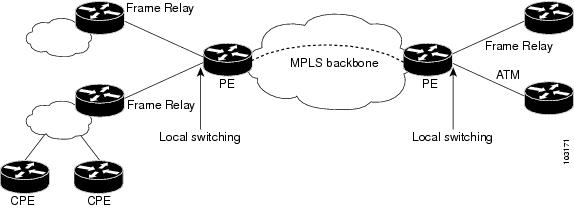
Figure 1 shows a network that uses local switching for both Frame Relay to Frame Relay and ATM to Frame Relay local switching.
Figure 1 Local Switching Example
Access Circuit Redundancy Local Switching
The Automatic Protection Switching (APS) mechanism provides a switchover time of less than 50 milliseconds. However, the switchover time is longer in a pseudowire configuration due to the time the pseudowire takes to enter the UP state on switchover. The switchover time of the pseudowire can be eliminated if there is a single pseudowire on the working and protect interfaces instead of separate pseudowire configurations. A single pseudowire also eliminates the need to have Label Distribution Protocols (LDP) negotiations on a switchover. The virtual interface or controller model provides a method to configure a single pseudowire between the provider edge (PE) routers.
Access Circuit Redundancy (ACR) ensures low data traffic downtime by reducing the switchover time. ACR works on the APS 1+1, nonrevertive model where each redundant line pair consists of a working line and a protect line. If a signal fail condition or a signal degrade condition is detected, the hardware switches from the working line to the protect line.
The working and protect interfaces can be on the following:
•![]() Same SPA
Same SPA
•![]() Different SPA but on the same line card
Different SPA but on the same line card
•![]() SPAs on different line cards
SPAs on different line cards
When the working or protection interface is configured with ACR, a virtual interface is created and a connection is established between the virtual interfaces to facilitate the switching of data between the interfaces.
This section describes the following:
•![]() ACR for ATM-to-ATM Local Switching
ACR for ATM-to-ATM Local Switching
•![]() ACR for CEM-to-CEM Local Switching
ACR for CEM-to-CEM Local Switching
ACR for ATM-to-ATM Local Switching
ACR for ATM-to-ATM local switching supports the ATM AAL5 and ATM AAL0 encapsulation types and switches Layer 2 data between L2 transport virtual circuits (VCs).
Note ![]() The L2 transport VCs must be configured with the same encapsulation type.
The L2 transport VCs must be configured with the same encapsulation type.
Figure 2 shows the ACR for ATM-to-ATM local switching model.
Figure 2 ATM-to-ATM ACR Local Switching Model
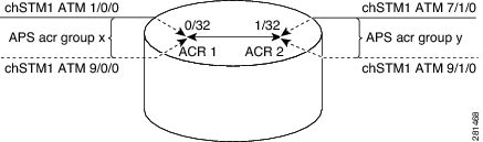
In the figure:
•![]() ATM 1/0/0 and ATM 9/0/0 are configured as working and protection interfaces of ACR 1 group.
ATM 1/0/0 and ATM 9/0/0 are configured as working and protection interfaces of ACR 1 group.
•![]() ATM 7/1/0 and ATM 9/1/0 are configured as working and protection interfaces of ACR 2 group.
ATM 7/1/0 and ATM 9/1/0 are configured as working and protection interfaces of ACR 2 group.
•![]() A connection is established between the ACRs.
A connection is established between the ACRs.
•![]() The Add/Drop Multiplexer (ADM) sends data to both the interfaces, which are part of the ACR group ACR 1.
The Add/Drop Multiplexer (ADM) sends data to both the interfaces, which are part of the ACR group ACR 1.
•![]() The cells or packets received on the APS active interface VC (0/32) of ACR group 1 are switched to the ACR 2 interface VC (1/32) and the cells or packets from the APS inactive interface are dropped.
The cells or packets received on the APS active interface VC (0/32) of ACR group 1 are switched to the ACR 2 interface VC (1/32) and the cells or packets from the APS inactive interface are dropped.
•![]() The packets received on the ACR 2 VC (1/32) interface are replicated on both the physical interfaces, which are part of the ACR group ACR 2.
The packets received on the ACR 2 VC (1/32) interface are replicated on both the physical interfaces, which are part of the ACR group ACR 2.
ACR for CEM-to-CEM Local Switching
Circuit Emulation (CEM) transports Time Division Multiplexing (TDM) data over TDM pseudowires, allowing mobile operators to carry TDM traffic over an IP or Multiprotocol Label Switching (MPLS) network. ACR for CEM-to-CEM involves creating a virtual controller and associating the virtual controller with the physical controllers. The virtual controller is created when APS and ACR are configured on the physical controller. All commands executed on the virtual controller apply to the working and protect controller. The virtual controller simplifies the single point of configuration and provides the flexibility of not running a backup pseudowire for the protect controller in the event of a failure. This way there is no switchover between the pseudowires, which in turn reduces the recovery time when the physical link fails.
When the CEM group is configured on the virtual controller, a virtual CEM-ACR interface is created and associated with the CEM circuit. ACR creates CEM interfaces and CEM circuits on the physical interfaces that correspond to the physical controllers belonging to the same ACR group.
Figure 3 shows the ACR for CEM-to-CEM local switching model:
Figure 3 CEM-to-CEM ACR Local Switching Model
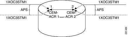
In the figure:
•![]() Packets are received from the ADM. The packets from the APS inactive interface are dropped and the packets received on the APS active interface are switched.
Packets are received from the ADM. The packets from the APS inactive interface are dropped and the packets received on the APS active interface are switched.
•![]() The packets received on the CEM circuit ID 1 of the APS active interface, which is part of ACR group 1, are switched to the CEM circuit ID 2 of the APS active interface, which is part of ACR group 2.
The packets received on the CEM circuit ID 1 of the APS active interface, which is part of ACR group 1, are switched to the CEM circuit ID 2 of the APS active interface, which is part of ACR group 2.
•![]() The packets are duplicated and sent on both the APS active and inactive physical CEM interfaces that are part of ACR group 2.
The packets are duplicated and sent on both the APS active and inactive physical CEM interfaces that are part of ACR group 2.
How to Configure Layer 2 Local Switching
•![]() Configuring ATM-to-ATM PVC Local Switching and Same-Port Switching (optional)
Configuring ATM-to-ATM PVC Local Switching and Same-Port Switching (optional)
•![]() Configuring ATM-to-ATM PVP Local Switching (optional)
Configuring ATM-to-ATM PVP Local Switching (optional)
•![]() Configuring ATM PVP Same-Port Switching (optional)
Configuring ATM PVP Same-Port Switching (optional)
•![]() Configuring ATM-to-Ethernet Port Mode Local Switching (optional)
Configuring ATM-to-Ethernet Port Mode Local Switching (optional)
•![]() Configuring ATM-to-Ethernet VLAN Mode Local Switching (optional)
Configuring ATM-to-Ethernet VLAN Mode Local Switching (optional)
•![]() Configuring Ethernet VLAN Same-Port Switching (optional)
Configuring Ethernet VLAN Same-Port Switching (optional)
•![]() Configuring Ethernet Port Mode to Ethernet VLAN Local Switching (optional)
Configuring Ethernet Port Mode to Ethernet VLAN Local Switching (optional)
•![]() Configuring ATM-to-Frame Relay Local Switching (optional)
Configuring ATM-to-Frame Relay Local Switching (optional)
•![]() Configuring Frame Relay-to-Frame Relay Local Switching (optional)
Configuring Frame Relay-to-Frame Relay Local Switching (optional)
•![]() Configuring Frame Relay Same-Port Switching (optional)
Configuring Frame Relay Same-Port Switching (optional)
•![]() Configuring HDLC Local Switching (optional)
Configuring HDLC Local Switching (optional)
•![]() Configuring ACR for ATM-to-ATM Local Switching (optional)
Configuring ACR for ATM-to-ATM Local Switching (optional)
•![]() Configuring CEM-to-CEM ACR Local Switching (optional)
Configuring CEM-to-CEM ACR Local Switching (optional)
•![]() Verifying Layer 2 Local Switching (optional)
Verifying Layer 2 Local Switching (optional)
For information about Layer 2 local switching on the Cisco 10000 series routers, see Configuring Layer 2 Local Switching.
Configuring ATM-to-ATM PVC Local Switching and Same-Port Switching
You can configure local switching for both ATM AAL5 and ATM AAL0 encapsulation types.
Creating the ATM PVC is not required. If you do not create a PVC, one is created for you. For ATM-to-ATM local switching, the autoprovisioned PVC is given the default encapsulation type AAL0 cell relay.
Note ![]() Starting with Cisco IOS Release 12.0(30)S, you can configure same-port switching following the steps in this section.
Starting with Cisco IOS Release 12.0(30)S, you can configure same-port switching following the steps in this section.
Perform this task to configure ATM-to-ATM PVC local switching and same-port switching.
SUMMARY STEPS
1. ![]() enable
enable
2. ![]() configure terminal
configure terminal
3. ![]() interface atmslot/port
interface atmslot/port
4. ![]() pvc vpi/vci l2transport
pvc vpi/vci l2transport
5. ![]() encapsulation layer-type
encapsulation layer-type
6. ![]() exit
exit
7. ![]() exit
exit
8. ![]() connect connection-name interface pvc interface pvc
connect connection-name interface pvc interface pvc
DETAILED STEPS
Configuring ATM-to-ATM PVP Local Switching
Perform this task to configure ATM-to-ATM PVP local switching.
Starting with Cisco IOS Release 12.0(30)S, you can configure same-port switching, as detailed in the "Configuring ATM PVP Same-Port Switching" section.
SUMMARY STEPS
1. ![]() enable
enable
2. ![]() configure terminal
configure terminal
3. ![]() interface atmslot/port
interface atmslot/port
4. ![]() atm pvp vpi l2transport
atm pvp vpi l2transport
5. ![]() exit
exit
6. ![]() exit
exit
7. ![]() connect connection-name interface pvp interface pvp
connect connection-name interface pvp interface pvp
DETAILED STEPS
Configuring ATM PVP Same-Port Switching
Perform this task to configure ATM PVP switching on an ATM interface.
SUMMARY STEPS
1. ![]() enable
enable
2. ![]() configure terminal
configure terminal
3. ![]() interface atmslot/subslot/port
interface atmslot/subslot/port
4. ![]() atm pvp vpi l2transport
atm pvp vpi l2transport
5. ![]() exit
exit
6. ![]() exit
exit
7. ![]() connect connection-name interface pvp interface pvp
connect connection-name interface pvp interface pvp
DETAILED STEPS
Configuring ATM-to-Ethernet Port Mode Local Switching
For ATM to Ethernet port mode local switching, creating the ATM PVC is not required. If you do not create a PVC, one is created for you. For ATM-to-Ethernet local switching, the autoprovisioned PVC is given the default encapsulation type AAL5SNAP.
ATM-to-Ethernet local switching supports both the IP and Ethernet interworking types. When the Ethernet interworking type is used, the interworking device (router) expects a bridged packet. Therefore, configure the ATM CPE for either IRB or RBE.
Note ![]() Enabling ICMP Router Discovery Protocol on the Ethernet side is recommended.
Enabling ICMP Router Discovery Protocol on the Ethernet side is recommended.
ATM-to-Ethernet local switching supports the following encapsulation types:
•![]() ATM-to-Ethernet with IP interworking: AAL5SNAP, AAL5MUX
ATM-to-Ethernet with IP interworking: AAL5SNAP, AAL5MUX
•![]() ATM-to-Ethernet with Ethernet interworking: AAL5SNAP
ATM-to-Ethernet with Ethernet interworking: AAL5SNAP
Perform this task to configure local switching between ATM and Ethernet port mode.
SUMMARY STEPS
1. ![]() enable
enable
2. ![]() configure terminal
configure terminal
3. ![]() interface atmslot/port
interface atmslot/port
4. ![]() pvc vpi/vci l2transport
pvc vpi/vci l2transport
5. ![]() encapsulation layer-type
encapsulation layer-type
6. ![]() exit
exit
7. ![]() exit
exit
8. ![]() interface fastethernetslot/subslot/port
interface fastethernetslot/subslot/port
9. ![]() exit
exit
10. ![]() connect connection-name interface pvc interface [interworking ip | ethernet]
connect connection-name interface pvc interface
[interworking ip | ethernet]
DETAILED STEPS
Configuring ATM-to-Ethernet VLAN Mode Local Switching
For ATM-to-Ethernet VLAN mode local switching, creating the ATM PVC is not required. If you do not create a PVC, one is created for you. For ATM-to-Ethernet local switching, the autoprovisioned PVC is given the default encapsulation type AAL5SNAP.
ATM-to-Ethernet local switching supports both the IP and Ethernet interworking types. When the Ethernet interworking type is used, the interworking device (router) expects a bridged packet. Therefore, configure the ATM CPE for either IRB or RBE.
Note ![]() Enabling ICMP Router Discovery Protocol on the Ethernet side is recommended.
Enabling ICMP Router Discovery Protocol on the Ethernet side is recommended.
ATM-to-Ethernet local switching supports the following encapsulation types:
•![]() ATM-to-Ethernet with IP interworking: AAL5SNAP, AAL5MUX
ATM-to-Ethernet with IP interworking: AAL5SNAP, AAL5MUX
•![]() ATM-to-Ethernet with Ethernet interworking: AAL5SNAP
ATM-to-Ethernet with Ethernet interworking: AAL5SNAP
The VLAN header is removed from frames that are received on an Ethernet subinterface.
Perform this task to configure local switching for ATM to Ethernet in VLAN mode.
SUMMARY STEPS
1. ![]() enable
enable
2. ![]() configure terminal
configure terminal
3. ![]() interface atmslot/subslot/port
interface atmslot/subslot/port
4. ![]() pvc vpi/vci l2transport
pvc vpi/vci l2transport
5. ![]() encapsulation layer-type
encapsulation layer-type
6. ![]() exit
exit
7. ![]() interface fastethernetslot/port/subinterface-number
interface fastethernetslot/port/subinterface-number
8. ![]() encapsulation dot1q vlan-id
encapsulation dot1q vlan-id
9. ![]() exit
exit
10. ![]() connect connection-name interface pvc interface [interworking ip | ethernet]
connect connection-name interface pvc interface [interworking ip | ethernet]
DETAILED STEPS
Configuring Ethernet VLAN Same-Port Switching
Perform this task to configure Ethernet VLAN same-port switching.
SUMMARY STEPS
1. ![]() enable
enable
2. ![]() configure terminal
configure terminal
3. ![]() interface fastethernetslot/port.subinterface-number
interface fastethernetslot/port.subinterface-number
4. ![]() encapsulation dot1q vlan-id
encapsulation dot1q vlan-id
5. ![]() exit
exit
6. ![]() interface fastethernetslot/port.subinterface-number
interface fastethernetslot/port.subinterface-number
7. ![]() encapsulation dot1q vlan-id
encapsulation dot1q vlan-id
8. ![]() exit
exit
9. ![]() connect connection-name interface interface
connect connection-name interface interface
DETAILED STEPS
Configuring Ethernet Port Mode to Ethernet VLAN Local Switching
Perform this task to configure local switching for Ethernet (port mode) to Ethernet VLAN.
SUMMARY STEPS
1. ![]() enable
enable
2. ![]() configure terminal
configure terminal
3. ![]() interface fastethernetslot/subslot/port
interface fastethernetslot/subslot/port
4. ![]() interface fastethernetslot/port/subinterface-number
interface fastethernetslot/port/subinterface-number
5. ![]() encapsulation dot1q vlan-id
encapsulation dot1q vlan-id
6. ![]() exit
exit
7. ![]() connect connection-name interface interface [interworking ip | ethernet]
connect connection-name interface interface [interworking ip | ethernet]
DETAILED STEPS
Configuring ATM-to-Frame Relay Local Switching
You use the interworking ip keywords for configuring ATM-to-Frame Relay local switching.
FRF.8 Frame Relay-to-ATM service interworking functionality is not supported. Frame Relay discard-eligible (DE) bits do not get mapped to ATM cell loss priority (CLP) bits, and forward explicit congestion notification (FECN) bits do not get mapped to ATM explicit forward congestion indication (EFCI) bits.
Creating the PVC is not required. If you do not create a PVC, one is created for you. For ATM-to-Ethernet local switching, the automatically provisioned PVC is given the default encapsulation type AAL5SNAP.
ATM-to-Frame Relay local switching supports the following encapsulation types:
•![]() AAL5SNAP
AAL5SNAP
•![]() AAL5NLPID (GSR uses AAL5MUX instead, for IP interworking)
AAL5NLPID (GSR uses AAL5MUX instead, for IP interworking)
SUMMARY STEPS
1. ![]() enable
enable
2. ![]() configure terminal
configure terminal
3. ![]() interface atmslot/port
interface atmslot/port
4. ![]() pvc vpi/vci l2transport
pvc vpi/vci l2transport
5. ![]() encapsulation layer-type
encapsulation layer-type
6. ![]() exit
exit
7. ![]() interface serialslot/port
interface serialslot/port
8. ![]() encapsulation frame-relay [cisco | ietf]
encapsulation frame-relay [cisco | ietf]
9. ![]() frame-relay interface-dlci dlci switched
frame-relay interface-dlci dlci switched
10. ![]() exit
exit
11. ![]() connect connection-name interface pvc interface dlci [interworking ip | ethernet]
connect connection-name interface pvc interface dlci [interworking ip | ethernet]
DETAILED STEPS
Configuring Frame Relay-to-Frame Relay Local Switching
For information on Frame Relay-to-Frame Relay Local Switching, see the Distributed Frame Relay Switching feature module.
With Cisco IOS Release 12.0(30)S, you can switch between virtual circuits on the same port, as detailed in the "Configuring Frame Relay Same-Port Switching" section.
SUMMARY STEPS
1. ![]() enable
enable
2. ![]() configure terminal
configure terminal
3. ![]() ip cef [distributed]
ip cef [distributed]
4. ![]() frame-relay switching
frame-relay switching
5. ![]() interface type number
interface type number
6. ![]() encapsulation frame-relay [cisco | ietf]
encapsulation frame-relay [cisco | ietf]
7. ![]() frame-relay interface-dlci dlci switched
frame-relay interface-dlci dlci switched
8. ![]() exit
exit
9. ![]() exit
exit
10. ![]() connect connection-name interface dlci interface dlci
connect connection-name interface dlci interface dlci
DETAILED STEPS
Configuring Frame Relay Same-Port Switching
Perform this task to configure Frame Relay switching on the same interface.
SUMMARY STEPS
1. ![]() enable
enable
2. ![]() configure terminal
configure terminal
3. ![]() ip cef [distributed]
ip cef [distributed]
4. ![]() frame-relay switching
frame-relay switching
5. ![]() interface type number
interface type number
6. ![]() encapsulation frame-relay [cisco | ietf]
encapsulation frame-relay [cisco | ietf]
7. ![]() frame-relay intf-type [dce | dte | nni]
frame-relay intf-type [dce | dte | nni]
8. ![]() frame-relay interface-dlci dlci switched
frame-relay interface-dlci dlci switched
9. ![]() exit
exit
10. ![]() exit
exit
11. ![]() connect connection-name interface dlci interface dlci
connect connection-name interface dlci interface dlci
DETAILED STEPS
Configuring HDLC Local Switching
Perform this task to configure local switching for HDLC. The PE routers are configured with HDLC encapsulation. The CE routers are configured with any HDLC-based encapsulation, including HDLC, PPP, and Frame Relay.
Prerequisites
•![]() Ensure that the interfaces you configure for HDLC encapsulation can handle ping packets that are smaller, the same size as, or larger than the CE interface MTU.
Ensure that the interfaces you configure for HDLC encapsulation can handle ping packets that are smaller, the same size as, or larger than the CE interface MTU.
•![]() Enable Cisco Express Forwarding.
Enable Cisco Express Forwarding.
Restrictions
•![]() Do not configure other settings on the interfaces configured for HDLC encapsulation. If you assign an IP address on the interface, the connect command is rejected and the following error message displays:
Do not configure other settings on the interfaces configured for HDLC encapsulation. If you assign an IP address on the interface, the connect command is rejected and the following error message displays:
Incompatible with IP address command on interface - command rejected.
If you configure other settings on the interface that is enabled for HDLC encapsulation, the local switching feature may not work.
•![]() Interworking is not supported.
Interworking is not supported.
•![]() Same-port local switching for HDLC is not supported.
Same-port local switching for HDLC is not supported.
•![]() Dialer and ISDN interfaces are not supported. Only serial, HSSI, and POS interfaces can be configured for HDLC local switching.
Dialer and ISDN interfaces are not supported. Only serial, HSSI, and POS interfaces can be configured for HDLC local switching.
SUMMARY STEPS
1. ![]() enable
enable
2. ![]() configure terminal
configure terminal
3. ![]() ip cef [distributed]
ip cef [distributed]
4. ![]() interface type number
interface type number
5. ![]() exit
exit
6. ![]() connect connection-name interface interface
connect connection-name interface interface
DETAILED STEPS
Configuring ACR for ATM-to-ATM Local Switching
Note ![]() The connect command provides an infrastructure to create the required L2 transport VCs with the default AAl0 encapsulation type and does not require that the VCs must exist.
The connect command provides an infrastructure to create the required L2 transport VCs with the default AAl0 encapsulation type and does not require that the VCs must exist.
Perform this task to configure ACR for ATM-to-ATM local switching.
SUMMARY STEPS
1. ![]() enable
enable
2. ![]() configure terminal
configure terminal
3. ![]() interface atmslot/subslot/port
interface atmslot/subslot/port
4. ![]() aps group [acr] group-number
aps group [acr] group-number
5. ![]() aps working circuit-number
aps working circuit-number
6. ![]() aps protect circuit-number ip-address
aps protect circuit-number ip-address
7. ![]() exit
exit
8. ![]() interface acr acr-group-number
interface acr acr-group-number
9. ![]() pvc [name] vpi/vci l2transport
pvc [name] vpi/vci l2transport
10. ![]() exit
exit
11. ![]() exit
exit
12. ![]() connect connection-name type number pvc type number pvc
connect connection-name type number pvc type number pvc
13. ![]() exit
exit
DETAILED STEPS
Configuring CEM-to-CEM ACR Local Switching
Perform this task to configure ACR for CEM-to-CEM local switching.
SUMMARY STEPS
1. ![]() enable
enable
2. ![]() configure terminal
configure terminal
3. ![]() controller sonet slot/subslot/port
controller sonet slot/subslot/port
4. ![]() aps group [acr] group-number
aps group [acr] group-number
5. ![]() aps working circuit-number
aps working circuit-number
6. ![]() aps protect circuit-number ip-address
aps protect circuit-number ip-address
7. ![]() exit
exit
8. ![]() controller sonet-acr acr-group-number
controller sonet-acr acr-group-number
9. ![]() framing sonet
framing sonet
10. ![]() sts-1 number
sts-1 number
11. ![]() mode vt-15
mode vt-15
12. ![]() vtg number t1 number cem-group number timeslots number
vtg number t1 number cem-group number timeslots number
13. ![]() exit
exit
14. ![]() exit
exit
15. ![]() interface cem-acr acr-group-number
interface cem-acr acr-group-number
16. ![]() exit
exit
17. ![]() cem slot/port/channel
cem slot/port/channel
18. ![]() xconnect virtual-connect-id
xconnect virtual-connect-id
19. ![]() exit
exit
20. ![]() exit
exit
21. ![]() connect connection-name type number circuit-id type number circuit-id
connect connection-name type number circuit-id type number circuit-id
22. ![]() exit
exit
DETAILED STEPS
Verifying Layer 2 Local Switching
•![]() Verifying Layer 2 Local Switching Configuration
Verifying Layer 2 Local Switching Configuration
•![]() Verifying the NSF SSO Local Switching Configuration
Verifying the NSF SSO Local Switching Configuration
Verifying Layer 2 Local Switching Configuration
To verify configuration of the Layer 2 Local Switching feature, use the following commands on the provider edge (PE) router:
SUMMARY STEPS
1. ![]() show connection [all | element | id id | name name | port port]
show connection [all | element | id id | name name | port port]
2. ![]() show atm pvc
show atm pvc
3. ![]() show frame-relay pvc [pvc]
show frame-relay pvc [pvc]
DETAILED STEPS
Step 1 ![]() show connection [all | element | id id | name name | port port]
show connection [all | element | id id | name name | port port]
The show connection command displays the local connection between an ATM interface and a Fast Ethernet interface:
Router# show connection name atm-eth-con
ID Name Segment 1 Segment 2 State
==================================================================
1 atm-eth-con ATM0/0/0 AAL5 0/100 FastEthernet6/0/0 UP
This example displays the local connection between an ATM interface and a serial interface:
Router# show connection name atm-fr-con
ID Name Segment 1 Segment 2 State
==================================================================
1 atm-fr-con ATM0/0/0 AAL5 0/100 Serial1/0/0 16 UP
This example displays a same-port connection on a serial interface.
Router# show connection name same-port
ID Name Segment 1 Segment 2 State
==================================================================
1 same-port Serial1/1/1 101 Serial1/1/1 102 UP
Step 2 ![]() show atm pvc
show atm pvc
The show atm pvc command shows that interface ATM3/0 is UP:
Router# show atm pvc
VCD/ Peak Avg/Min Burst
Interface Name VPI VCI Type Encaps SC Kbps Kbps Cells Sts
3/0 10 1 32 PVC FRATMSRV UBR 155000 UP
Step 3 ![]() show frame-relay pvc [pvc]
show frame-relay pvc [pvc]
The show frame-relay pvc command shows a switched Frame Relay PVC:
Router# show frame-relay pvc 16
PVC Statistics for interface POS5/0 (Frame Relay NNI)
DLCI = 16, DLCI USAGE = SWITCHED, PVC STATUS = UP, INTERFACE = POS5/0
LOCAL PVC STATUS = UP, NNI PVC STATUS = ACTIVE
input pkts 0 output pkts 0 in bytes 0
out bytes 0 dropped pkts 100 in FECN pkts 0
in BECN pkts 0 out FECN pkts 0 out BECN pkts 0
in DE pkts 0 out DE pkts 0
out bcast pkts 0 out bcast bytes 0
switched pkts 0
Detailed packet drop counters:
no out intf 0 out intf down 100 no out PVC 0
in PVC down 0 out PVC down 0 pkt too big 0
pvc create time 00:25:32, last time pvc status changed 00:06:31
Verifying the NSF SSO Local Switching Configuration
Layer 2 local switching provides NSF/SSO support for Local Switching of the following attachment circuits on the same router:
•![]() Ethernet (port mode) to Ethernet VLAN
Ethernet (port mode) to Ethernet VLAN
•![]() Frame Relay to Frame Relay
Frame Relay to Frame Relay
For information about configuring NSF/SSO on the RPs, see the Stateful Switchover feature module. To verify that the NSF/SSO: Layer 2 Local Switching is working correctly, follow the steps in this section.
SUMMARY STEPS
1. ![]() ping
ping
2. ![]() redundancy force-switchover
redundancy force-switchover
3. ![]() show connect all
show connect all
4. ![]() ping
ping
DETAILED STEPS
Step 1 ![]() Issue the ping command or initiate traffic between the two CE routers.
Issue the ping command or initiate traffic between the two CE routers.
Step 2 ![]() Force the switchover from the active RP to the standby RP by using the redundancy force-switchover command. This manual procedure allows for a "graceful" or controlled shutdown of the active RP and switchover to the standby RP. This graceful shutdown allows critical cleanup to occur.
Force the switchover from the active RP to the standby RP by using the redundancy force-switchover command. This manual procedure allows for a "graceful" or controlled shutdown of the active RP and switchover to the standby RP. This graceful shutdown allows critical cleanup to occur.
Step 3 ![]() Issue the show connect all command to ensure that the Layer 2 local switching connection on the dual RP is operating.
Issue the show connect all command to ensure that the Layer 2 local switching connection on the dual RP is operating.
Router# show connect all
ID Name Segment 1 Segment 2 State
2 Eth-Vlan1 Fa1/1/1 Fa6/0/0/0.1 UP
Step 4 ![]() Issue the ping command from the CE router to verify that the contiguous packet outage was minimal during the switchover.
Issue the ping command from the CE router to verify that the contiguous packet outage was minimal during the switchover.
Troubleshooting Tips
You can troubleshoot Layer 2 local switching using the following commands on the PE router:
•![]() debug atm l2transport
debug atm l2transport
•![]() debug conn
debug conn
•![]() debug frame-relay pseudowire
debug frame-relay pseudowire
•![]() show frame-relay pvc
show frame-relay pvc
•![]() show connection
show connection
•![]() show atm pvc
show atm pvc
Configuration Examples for Layer 2 Local Switching
•![]() Example: ATM-to-ATM Local Switching
Example: ATM-to-ATM Local Switching
•![]() Example: ATM PVC Same-Port Switching
Example: ATM PVC Same-Port Switching
•![]() Example: ATM PVP Same-Port Switching
Example: ATM PVP Same-Port Switching
•![]() Example: ATM-to-Ethernet Local Switching
Example: ATM-to-Ethernet Local Switching
•![]() Example: Ethernet VLAN Same-Port Switching
Example: Ethernet VLAN Same-Port Switching
•![]() Example: ATM-to-Frame Relay Local Switching
Example: ATM-to-Frame Relay Local Switching
•![]() Example: Frame Relay-to-Frame Relay Local Switching
Example: Frame Relay-to-Frame Relay Local Switching
•![]() Example: Frame Relay DLCI Same-Port Switching
Example: Frame Relay DLCI Same-Port Switching
•![]() Example: HDLC Local Switching
Example: HDLC Local Switching
•![]() Example: NSF SSO: Ethernet Port Mode to Ethernet VLAN Local Switching
Example: NSF SSO: Ethernet Port Mode to Ethernet VLAN Local Switching
Example: ATM-to-ATM Local Switching
The following example shows local switching on ATM interfaces configured for AAL5:
interface atm1/0/0
pvc 0/100 l2transport
encapsulation aal5
interface atm2/0/0
pvc 0/100 l2transport
encapsulation aal5
connect aal5-conn atm1/0/0 0/100 atm2/0/0 0/100
Example: ATM PVC Same-Port Switching
The following example shows same-port switching between two PVCs on one ATM interface:
interface atm1/0/0
pvc 0/100 l2transport
encapsulation aal5
pvc 0/200 l2transport
encapsulation aal5
connect conn atm1/0/0 0/100 atm1/0/0 0/200
Example: ATM PVP Same-Port Switching
The following example shows same-port switching between two PVPs on one ATM interface:
interface atm1/0/0
atm pvp 100 l2transport
atm pvp 200 l2transport
connect conn atm1/0/0 100 atm1/0/0 200
Example: ATM-to-Ethernet Local Switching
ATM-to-Ethernet local switching terminates an ATM frame to an Ethernet/VLAN frame over the same PE router. Two interworking models are used: Ethernet mode and IP mode.
Example: ATM to Ethernet VLAN
The following example shows an Ethernet interface configured for Ethernet VLAN, and an ATM PVC interface configured for AAL5 encapsulation. The connect command allows local switching between these two interfaces and specifies the interworking type as Ethernet mode.
interface fastethernet6/0/0.1
encapsulation dot1q 10
interface atm2/0/0
pvc 0/400 l2transport
encapsulation aal5
connect atm-ethvlan-con atm2/0/0 0/400 fastethernet6/0/0.1 interworking ethernet
Example: ATM to Ethernet Port Mode
The following example shows an Ethernet interface configured for Ethernet and an ATM interface configured for AAL5SNAP encapsulation. The connect command allows local switching between these two interfaces and specifies the interworking type as IP mode.
interface atm0/0/0
pvc 0/100 l2transport
encapsulation aal5snap
interface fastethernet6/0/0
connect atm-eth-con atm0/0/0 0/100 fastethernet6/0/0 interworking ip
Example: Ethernet VLAN Same-Port Switching
The following example shows same-port switching between two VLANs on one Ethernet interface:
interface fastethernet0/0.1
encapsulation dot1q 1
interface fastethernet0/0.2
encapsulation dot1q 2
connect conn FastEthernet0/0.1 FastEthernet0/0.2
Example: ATM-to-Frame Relay Local Switching
The following example shows a serial interface configured for Frame Relay and an ATM interface configured for AAL5SNAP encapsulation. The connect command allows local switching between these two interfaces.
interface serial1/0
encapsulation frame-relay
interface atm1/0
pvc 7/100 l2transport
encapsulation aal5snap
connect atm-fr-conn atm1/0 7/100 serial1/0 100 interworking ip
Example: Frame Relay-to-Frame Relay Local Switching
The following example shows serial interfaces configured for Frame Relay. The connect command allows local switching between these two interfaces.
frame-relay switching
ip cef distributed
interface serial3/0/0
encapsulation frame-relay
frame-relay interface-dlci 100 switched
frame-relay intf-type dce
interface serial3/1/0
encapsulation frame-relay ietf
frame-relay interface-dlci 200 switched
frame-relay intf-type dce
connect fr-con serial3/0/0 100 serial3/1/0 200
Example: Frame Relay DLCI Same-Port Switching
The following example shows same-port switching between two data links on one Frame Relay interface:
interface serial1/0
encapsulation frame-relay
frame-relay int-type nni
connect conn serial1/0 100 serial1/0 200
Example: HDLC Local Switching
The following example shows local switching of two serial interfaces for HDLC:
interface serial1/0
no ip address
interface serial2/0
no ip address
connect conn1 serial1/0 serial1/0
Example: NSF SSO: Ethernet Port Mode to Ethernet VLAN Local Switching
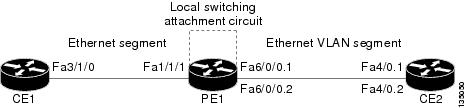
The following configuration uses the network topology shown in Figure 4.
Figure 4 NSF/SSO: Layer 2 Local Switching: Ethernet to Ethernet VLAN
The following example shows the configuration of the CE interfaces to connect to the PE1 router:
The following example shows the configuration of the PE1 router with NSF/SSO and the PE interfaces to the CE routers:
The following example shows the configuration of ICMP Router Discovery Protocol (IRDP) on the CE router for Interworking IP for ARP mediation:
|
|
|
|---|---|
interface FastEthernet3/1/0 ip irdp ip irdp maxadvertinterval 0 |
interface FastEthernet4/0.1 ip irdp ip irdp maxadvertinterval 0 |
The following example shows the configuration of OSPF on the CE routers:
The following example shows the configuration of local switching on the PE1 router for interworking Ethernet:
connect eth-vlan1 fa1/1/1 fa6/0/0.1 interworking ethernet
connect eth-vlan2 fa4/0/0 fa6/0/0.2 interworking ethernet
The following example shows the configuration of local switching on the PE1 router for interworking IP:
connect eth-vlan1 fa1/1/1 fa6/0/0.1 interworking ip
connect eth-vlan2 fa4/0/0 fa6/0/0.2 interworking ip
Additional References
Related Documents
Standards
MIBs
|
|
|
|---|---|
None |
To locate and download MIBs for selected platforms, Cisco software releases, and feature sets, use Cisco MIB Locator found at the following URL: |
RFCs
|
|
|
|---|---|
None |
— |
Technical Assistance
Feature Information for Layer 2 Local Switching
Table 1 lists the features in this module and provides links to specific configuration information.
Use Cisco Feature Navigator to find information about platform support and software image support. Cisco Feature Navigator enables you to determine which software images support a specific software release, feature set, or platform. To access Cisco Feature Navigator, go to http://www.cisco.com/go/cfn. An account on Cisco.com is not required.
Note ![]() Table 1 lists only the software release that introduced support for a given feature in a given software release train. Unless noted otherwise, subsequent releases of that software release train also support that feature.
Table 1 lists only the software release that introduced support for a given feature in a given software release train. Unless noted otherwise, subsequent releases of that software release train also support that feature.
|
|
|
|
|---|---|---|
Layer 2 Local Switching |
12.0(27)S |
The Layer 2 Local Switching feature allows you to switch Layer 2 data between two interfaces on the same router, and in some cases to switch Layer 2 data between two circuits on the same interface port. The feature was introduced in Cisco IOS Release 12.0(27)S on the Cisco 7200 and 7500 series routers. The feature was integrated into Cisco IOS Release 12.2(25)S for the Cisco 7500 series router. In Cisco IOS Release 12.0(30)S, support for same-port switching was added. Support for Layer 2 interface-to-interface local switching was added on the GSR. In Cisco IOS Release 12.0(31)S2, support was added for customer edge-facing IP Service Engine (ISE) interfaces on the GSR. In Cisco IOS Release 12.0(32)SY, support was added for customer edge-facing interfaces on Engine 5 shared port adapters (SPAs) and SPA Interface Processors (SIPs) on the GSR. In Cisco IOS Release 12.2(28)SB, this feature was updated to include NSF/SSO support on the Cisco 7500 series routers for the following local switching types on nonstop forwarding/stateful switchover (NSF/SSO): • • In Cisco IOS Release 12.4(11)T, support was added for the following local switching types for the Cisco 7200 series router: • • • • In Cisco IOS Release 12.2(28)SB, supported was added for Local Switching on the Cisco 10000 series router. In Cisco IOS Release 12.2(33)SXH, support was added for like-to-like Local Switching (ATM to ATM, and FR to FR only) on Cisco 6500 series switches and Cisco 7600 series routers. Same-port switching is not supported on those routers. In Cisco IOS Release 12.2(33)SB, support was added for HDLC Local Switching on the Cisco 7200 series router and the Cisco 10000 series router. The following sections provide information about this feature: • • The following commands were introduced or modified: connect (L2VPN local switching), encapsulation (Layer 2 local switching), show connection. |
Access Circuit Redundancy for ATM Local Switching |
15.1(1)S |
Access Circuit Redundancy (ACR) ensures low data traffic downtime by reducing the switchover time. ACR works on the APS 1+1, nonrevertive model where each redundant line pair consists of a working line and a protect line. If a signal fail condition or a signal degrade condition is detected, the hardware switches from the working line to the protect line. In Cisco IOS Release 15.1(1)S, this feature was introduced. The following sections provide information about this feature: • • The following commands were introduced or modified: aps group, connect (L2VPN local switching). |
ACR support for CEM |
15.1(1)S |
This feature provides Access Circuit Redundancy (ACR) support for CEM. In Cisco IOS Release 15.1(1)S, this feature was introduced. The following sections provide information about this feature: • • The following commands were introduced or modified: aps group, connect (L2VPN local switching). |
 Feedback