-
- Configuring Frame Relay
- Frame Relay 64-Bit Counters
- Frame Relay Queueing and Fragmentation at the Interface
- Frame Relay PVC Bundles with QoS Support for IP and MPLS
- Frame Relay PVC Interface Priority Queueing
- Frame Relay IP RTP Priority
- PPP over Frame Relay
- Multilink Frame Relay (FRF.16.1)
- Distributed Multilink Frame Relay (FRF.16)
- Layer 2 Tunneling Protocol Version 3
- Configuring SMDS
- L2VPN Pseudowire Redundancy
- L2VPN Interworking
- Layer 2 Local Switching
Cisco IOS Wide-Area Networking Configuration Guide, Release 12.2SR
Bias-Free Language
The documentation set for this product strives to use bias-free language. For the purposes of this documentation set, bias-free is defined as language that does not imply discrimination based on age, disability, gender, racial identity, ethnic identity, sexual orientation, socioeconomic status, and intersectionality. Exceptions may be present in the documentation due to language that is hardcoded in the user interfaces of the product software, language used based on RFP documentation, or language that is used by a referenced third-party product. Learn more about how Cisco is using Inclusive Language.
- Updated:
- February 5, 2008
Chapter: Frame Relay PVC Bundles with QoS Support for IP and MPLS
- Finding Feature Information
- Contents
- Prerequisites for Frame Relay PVC Bundles with QoS Support for IP and MPLS
- Restrictions for Frame Relay PVC Bundles with QoS Support for IP and MPLS
- Information About Frame Relay PVC Bundles with QoS Support for IP and MPLS
Frame Relay PVC Bundles with QoS Support for IP and MPLS
Frame Relay permanent virtual circuit (PVC) bundle functionality allows you to associate a group of Frame Relay PVCs with a single next-hop address. When Frame Relay PVC bundles are used with IP, packets are mapped to specific PVCs in the bundle on the basis of the precedence value or differentiated services code point (DSCP) settings in the type of service (ToS) field of the IP header. Each packet is treated differently according to the QoS configured for each PVC.
MPLS QoS support for Frame Relay PVC bundles extends Frame Relay PVC bundle functionality to support the mapping of Multiprotocol Label Switching (MPLS) packets to specific PVCs in the bundle. MPLS packets are mapped to PVCs according to the settings of the experimental (EXP) bits in the MPLS packet header.
Finding Feature Information
Your software release may not support all the features documented in this module. For the latest feature information and caveats, see the release notes for your platform and software release. To find information about the features documented in this module, and to see a list of the releases in which each feature is supported, see the "Feature Information for Frame Relay PVC Bundles with QoS Support for IP and MPLS" section.
Use Cisco Feature Navigator to find information about platform support and Cisco software image support. To access Cisco Feature Navigator, go to http://www.cisco.com/go/cfn. An account on Cisco.com is not required.
Contents
•![]() Prerequisites for Frame Relay PVC Bundles with QoS Support for IP and MPLS
Prerequisites for Frame Relay PVC Bundles with QoS Support for IP and MPLS
•![]() Restrictions for Frame Relay PVC Bundles with QoS Support for IP and MPLS
Restrictions for Frame Relay PVC Bundles with QoS Support for IP and MPLS
•![]() Information About Frame Relay PVC Bundles with QoS Support for IP and MPLS
Information About Frame Relay PVC Bundles with QoS Support for IP and MPLS
•![]() How to Configure Frame Relay PVC Bundles with QoS Support for IP and MPLS
How to Configure Frame Relay PVC Bundles with QoS Support for IP and MPLS
•![]() Configuration Examples for Frame Relay PVC Bundles with QoS Support for IP and MPLS
Configuration Examples for Frame Relay PVC Bundles with QoS Support for IP and MPLS
•![]() Feature Information for Frame Relay PVC Bundles with QoS Support for IP and MPLS
Feature Information for Frame Relay PVC Bundles with QoS Support for IP and MPLS
Prerequisites for Frame Relay PVC Bundles with QoS Support for IP and MPLS
To implement Frame Relay PVC bundles between two routers, you must enable IP Cisco Express Forwarding switching on the routers.
To configure MPLS EXP levels on bundle member PVCs, you must have tag-switching enabled on the interface.
It is recommended (but not required) that you implement PVC Interface Priority Queueing (PIPQ) in conjunction with Frame Relay PVC bundles. This will ensure that if the interface becomes congested, higher-priority traffic can exit the interface ahead of lower-priority traffic.
Restrictions for Frame Relay PVC Bundles with QoS Support for IP and MPLS
•![]() A PVC can be a part of one and only one PVC bundle.
A PVC can be a part of one and only one PVC bundle.
•![]() A PVC bundle may contain no more than eight PVCs.
A PVC bundle may contain no more than eight PVCs.
•![]() A PVC that is a bundle member cannot be used in any other capacity, For example a PVC bundle member cannot be configured in a map statement.
A PVC that is a bundle member cannot be used in any other capacity, For example a PVC bundle member cannot be configured in a map statement.
•![]() A PVC bundle cannot perform precedence and DSCP matching at the same time. If the wrong matching scheme is configured, unpredictable behavior will result.
A PVC bundle cannot perform precedence and DSCP matching at the same time. If the wrong matching scheme is configured, unpredictable behavior will result.
•![]() A PVC bundle will not come up unless all the precedence, DSCP, or EXP levels are configured in the bundle.
A PVC bundle will not come up unless all the precedence, DSCP, or EXP levels are configured in the bundle.
•![]() Voice over Frame Relay (VoFR) is not supported on PVC-bundle members.
Voice over Frame Relay (VoFR) is not supported on PVC-bundle members.
•![]() Fast switching over Frame Relay PVC bundles is not supported.
Fast switching over Frame Relay PVC bundles is not supported.
Information About Frame Relay PVC Bundles with QoS Support for IP and MPLS
•![]() Benefits of Frame Relay PVC Bundles with QoS Support for IP and MPLS
Benefits of Frame Relay PVC Bundles with QoS Support for IP and MPLS
•![]() Frame Relay PVC Bundle Support
Frame Relay PVC Bundle Support
•![]() Frame Relay PVC Bundle Management
Frame Relay PVC Bundle Management
Benefits of Frame Relay PVC Bundles with QoS Support for IP and MPLS
•![]() IP or MPLS packets carrying different types of traffic can be transported on different PVCs within the same PVC bundle.
IP or MPLS packets carrying different types of traffic can be transported on different PVCs within the same PVC bundle.
•![]() Precedence-based PVC bundles can be converted to EXP-based PVC bundles by enabling tag-switching. EXP-based PVC bundles can be converted to precedence-based PVC bundles by disabling tag-switching.
Precedence-based PVC bundles can be converted to EXP-based PVC bundles by enabling tag-switching. EXP-based PVC bundles can be converted to precedence-based PVC bundles by disabling tag-switching.
•![]() This feature provides flexible PVC management within a PVC bundle by allowing traffic assigned to a failed PVC to be redirected to an alternate PVC within the bundle. This feature also allows you to configure the bundle to go down when certain PVCs go down.
This feature provides flexible PVC management within a PVC bundle by allowing traffic assigned to a failed PVC to be redirected to an alternate PVC within the bundle. This feature also allows you to configure the bundle to go down when certain PVCs go down.
Frame Relay PVC Bundle Support
The use of Frame Relay PVC bundles allows you to configure multiple PVCs with different QoS characteristics between any pair of Frame Relay-connected routers. As shown in Figure 1, a PVC bundle may contain up to eight PVCs. The individual PVCs within a bundle are called bundle members.
To determine which PVC in a bundle will be used to forward a specific type of traffic, the router maps the IP precedence level or DSCP value in an IPv4 packet header to a PVC configured with the same value. In the case of MPLS, packets are mapped to specific PVCs in a bundle based on the settings of the EXP bits in the MPLS packet headers.
Once you define a Frame Relay bundle and add PVCs to it, you can configure attributes and characteristics to discrete PVC bundle members, or you can apply them collectively at the bundle level. Frame Relay traffic shaping may be applied to every PVC within a bundle. As with individual PVCs, you can enable rate adaptation to occur in response to incoming backward explicit congestion notifications (BECN) from the network.
Figure 1 Frame Relay PVC bundle
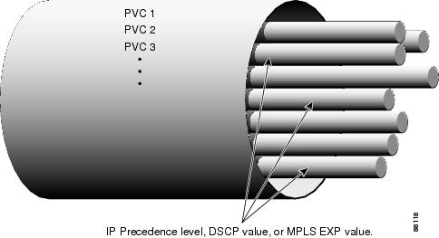
You can create differentiated service using PVC bundles by distributing IP precedence levels or DSCP values over the various bundle members. You can map either a single precedence level or a range of precedence levels to each PVC in the bundle. Thus, either you can limit an individual PVC to carry only packets marked with a specific precedence level or you can enable a PVC to carry packets marked with different precedence levels.
Service Levels and PVC Selection Criteria
The DSCP and Precedence bits classify IP packet service levels. The Precedence field consists of the first three bits of the ToS octet in the IPv4 header. These bits define eight precedence levels. When DSCP mapping is used, the DSCP octet replaces the ToS octet in the IPv4 header. Currently the first six bits are used, defining 64 service levels.
Using precedence-based or DSCP-based mapping, each IPv4 packet is mapped to a specific PVC in the bundle, according to the value of the ToS or DSCP octet in the IP header. There is no special treatment for broadcast or multicast or IP routing packets; the only differentiation in treatment is a result of the ToS or DSCP octet settings.
The MPLS EXP bits make up a three-bit experimental field in the MPLS packet header. They are a bit-by-bit copy of the IP Precedence bits and provide the same eight QoS levels. Under MPLS EXP-based mapping, each MPLS packet is mapped to a specific PVC in the bundle, according the setting of the EXP bits.
Frame Relay PVC Bundle Management
In addition to mapping specific traffic types to specific PVCs according to QoS parameters designated by the ToS or DSCP values in the IPv4 headers or EXP values in the MPLS headers, PVC bundle management takes care of handling non-IP traffic and determining what happens if a PVC goes down.
By default, Inverse Address Resolution Protocol (ARP) traffic and other critical non-IP traffic is carried by the PVC configured for carrying IP Precedence or EXP level 6 or DSCP level 63. You can select a PVC with a different QoS to carry Inverse ARP traffic if required. Noncritical non-IP traffic is carried by the PVC that configured for carrying IP precedence, EXP, or DSCP level 0.
It is important during configuration to account for every precedence, EXP, or DSCP level in the configuration of the PVC bundle members. If all the packet service levels are not accounted for, the PVC bundle will never come up.
Once a PVC bundle is up, if an individual bundle member goes down, an attempt is made to identify an alternate PVC to handle the packet service level or levels that were carried by the downed PVC. If no alternate PVC is found, the entire PVC bundle is brought down.
Traffic Bumping
You can configure each PVC bundle member to bump traffic to another PVC in the bundle in the event that the bundle member goes down. You can specify whether the bumping will be implicit or explicit bumping. You can also specify that a particular PVC will never accept bumped traffic from another PVC. The default conditions are to perform implicit traffic bumping and to accept bumped traffic.
Implicit bumping diverts the traffic from a failed PVC to the PVC having the next-lower service level. Explicit bumping forces the traffic to a specific PVC rather than allowing it to find a PVC carrying traffic of the next-lower service level. For example, PVC x, responsible for carrying precedence level 3 traffic, can be configured to bump its traffic to PVC y, responsible for carrying precedence level 6 traffic—provided that PVC y is configured to accept bumped traffic. If PVC x goes down, PVC y takes over. If PVC y is already down or goes down later, the alternate PVC selected will depend on the bumping rule for PVC y. If no alternate PVC can be found for bumped traffic, the entire PVC bundle goes down.
PVC-Bundle Protection Rules
Traffic bumping provides a way to keep a PVC bundle up and traffic flowing even though some individual PVCs may be down. Protection rules provide a way to force the PVC bundle down even though some individual PVCs are up and might be able to handle all the traffic, though perhaps not in a satisfactory manner.
You can configure a PVC bundle member as an individually protected PVC or as part of a PVC bundle protected group. Only one protected group may exist within a PVC bundle; however, many individually protected PVCs may exist. The protection rules add flexibility for controlling the PVC bundle state.
When any one individually protected PVC goes down, the entire bundle goes down. If all the PVCs in a protected group go down, the entire bundle goes down.
If no protection rule is specified, the PVC bundle goes down only when all the PVCs go down. However, protection is overridden if a PVC that has no place to bump its traffic goes down. In this case, the entire bundle will go down despite any protection rules that have been set up.
MPLS EXP-based Mapping
To enable MPLS EXP-based mapping, tag-switching must be enabled on the interface or subinterface by using the tag-switching ip command. When tag-switching is enabled, MPLS and IP packets can flow across the interface and PVC bundles that are configured for IP Precedence mapping are converted to MPLS EXP mapping. The PVC bundle functionality remains the same with respect to priority levels, bumping, and so on, but the match precedence command is replaced by match exp, and each precedence command is replaced by the exp command. The effect is that a bundle member PVC previously configured to carry precedence level 1 IP traffic now carries EXP level 1 MPLS traffic.
PVC bundles configured for DSCP mapping go down when tag-switching is enabled. The DSCP configuration for each bundle member PVC is reset, resulting in the PVCs being unmapped and Inverse ARP, bumping, and protection settings being unconfigured. The match dscp command is replaced by match exp command.
When tag-switching is disabled, the match precedence and match dscp commands are restored and the exp commands are replaced by precedence commands.
When tag-switching is enabled or disabled, PVC bundles configured for IP precedence mapping or MPLS EXP mapping will stay up and traffic will transmit over the appropriate bundle member PVCs.
How to Configure Frame Relay PVC Bundles with QoS Support for IP and MPLS
•![]() Configuring Frame Relay PVC Bundles with IP QoS Support (required)
Configuring Frame Relay PVC Bundles with IP QoS Support (required)
•![]() Configuring Frame Relay PVC Bundles with MPLS QoS Support (required)
Configuring Frame Relay PVC Bundles with MPLS QoS Support (required)
•![]() Verifying Frame Relay PVC Bundles Configuration (optional)
Verifying Frame Relay PVC Bundles Configuration (optional)
•![]() Monitoring and Maintaining Frame Relay PVC Bundles (optional)
Monitoring and Maintaining Frame Relay PVC Bundles (optional)
Configuring Frame Relay PVC Bundles with IP QoS Support
To configure Frame Relay PVC bundles for handling IP packets, perform the following steps:
SUMMARY STEPS
1. ![]() enable
enable
2. ![]() configure terminal
configure terminal
3. ![]() ip routing
ip routing
4. ![]() ip cef
ip cef
5. ![]() interface type number
interface type number
or
interface type number.subinterface-number [multipoint | point-to-point]
6. ![]() encapsulation frame-relay [cisco | ietf]
encapsulation frame-relay [cisco | ietf]
7. ![]() ip address ip-address mask [secondary]
ip address ip-address mask [secondary]
8. ![]() frame-relay map protocol protocol-address {dlci | vc-bundle vc-bundle-name} [broadcast] [ietf | cisco]
frame-relay map protocol protocol-address {dlci | vc-bundle vc-bundle-name} [broadcast] [ietf | cisco]
9. ![]() frame-relay vc-bundle vc-bundle-name
frame-relay vc-bundle vc-bundle-name
10. ![]() encapsulation [ cisco| ietf]
encapsulation [ cisco| ietf]
11. ![]() match {dscp dscp-value | precedence precedence-value}
match {dscp dscp-value | precedence precedence-value}
12. ![]() pvc dlci [vc-name]
pvc dlci [vc-name]
13. ![]() class name
class name
14. ![]() precedence {level | other}
precedence {level | other}
or
dscp {level | other}
15. ![]() bump {explicit level | implicit | traffic}
bump {explicit level | implicit | traffic}
16. ![]() protect {group | vc}
protect {group | vc}
17. ![]() inarp
inarp
18. ![]() end
end
19. ![]() Configure the PVC bundle on the peer router.
Configure the PVC bundle on the peer router.
DETAILED STEPS
Configuring Frame Relay PVC Bundles with MPLS QoS Support
To configure Frame Relay PVC bundles for handling MPLS packets, perform the following steps:
SUMMARY STEPS
1. ![]() enable
enable
2. ![]() configure terminal
configure terminal
3. ![]() ip routing
ip routing
4. ![]() ip cef
ip cef
5. ![]() interface type number
interface type number
or
interface {type slot | port-adapter | port.subinterface-number}[multipoint | point-to-point]
6. ![]() encapsulation frame-relay [cisco | ietf]
encapsulation frame-relay [cisco | ietf]
7. ![]() tag-switching ip
tag-switching ip
8. ![]() ip address ip-address mask [secondary]
ip address ip-address mask [secondary]
9. ![]() frame-relay map protocol protocol-address {dlci | vc-bundle vc-bundle-name} [broadcast] [ietf | cisco]
frame-relay map protocol protocol-address {dlci | vc-bundle vc-bundle-name} [broadcast] [ietf | cisco]
10. ![]() frame-relay vc-bundle vc-bundle-name
frame-relay vc-bundle vc-bundle-name
11. ![]() encapsulation [ietf | cisco]
encapsulation [ietf | cisco]
12. ![]() pvc dlci [vc-name]
pvc dlci [vc-name]
13. ![]() class name
class name
14. ![]() exp {level | other}
exp {level | other}
15. ![]() bump {explicit level | implicit | traffic}
bump {explicit level | implicit | traffic}
16. ![]() protect {group | vc}
protect {group | vc}
17. ![]() inarp
inarp
18. ![]() end
end
19. ![]() Configure the PVC bundle on the peer router.
Configure the PVC bundle on the peer router.
DETAILED STEPS
Verifying Frame Relay PVC Bundles Configuration
To verify the configuration and operation of Frame Relay PVC bundles with QoS support, perform the following optional steps:
SUMMARY STEPS
1. ![]() enable
enable
2. ![]() show frame-relay vc-bundle vc-bundle-name [detail]
show frame-relay vc-bundle vc-bundle-name [detail]
3. ![]() show frame-relay map
show frame-relay map
4. ![]() show frame-relay pvc
show frame-relay pvc
5. ![]() show frame-relay ip rtp header-compression [interface type number]
show frame-relay ip rtp header-compression [interface type number]
6. ![]() show frame-relay ip tcp header-compression [interface type number]
show frame-relay ip tcp header-compression [interface type number]
7. ![]() show adjacency [type number] [detail] [summary]
show adjacency [type number] [detail] [summary]
DETAILED STEPS
Monitoring and Maintaining Frame Relay PVC Bundles
To monitor and maintain Frame Relay PVC bundles, perform this task.
SUMMARY STEPS
1. ![]() enable
enable
2. ![]() debug frame-relay adjacency {pvc [dlci] | vc-bundle [vc-bundle-name]}
debug frame-relay adjacency {pvc [dlci] | vc-bundle [vc-bundle-name]}
3. ![]() debug frame-relay vc-bundle {detail | state-change} [vc-bundle-name]
debug frame-relay vc-bundle {detail | state-change} [vc-bundle-name]
DETAILED STEPS
Configuration Examples for Frame Relay PVC Bundles with QoS Support for IP and MPLS
•![]() PVC Bundles with IP QoS Support on Interfaces Example
PVC Bundles with IP QoS Support on Interfaces Example
•![]() PVC Bundle with IP QoS Support with Multiple QoS Parameters Example
PVC Bundle with IP QoS Support with Multiple QoS Parameters Example
•![]() PVC Bundle with MPLS QoS Support Example
PVC Bundle with MPLS QoS Support Example
•![]() Verifying Frame Relay PVC Bundle Configuration Examples
Verifying Frame Relay PVC Bundle Configuration Examples
•![]() Monitoring and Maintaining Frame Relay PVC Bundles Examples
Monitoring and Maintaining Frame Relay PVC Bundles Examples
PVC Bundles with IP QoS Support on Interfaces Example
The following example shows the configuration of five PVC bundles with IP precedence and DSCP mapping. Two bundles are configured on the main interface, one bundle with static mapping and one with dynamic mapping. Two bundles are configured on a multipoint subinterface, one bundle with static mapping and one with dynamic mapping. One bundle is configured on a point-to-point subinterface.
configure terminal
ip routing
ip cef
interface Serial 1/4
encapsulation frame-relay
frame-relay intf-type dte
ip address 10.1.1.1 255.0.0.0
frame-relay map ip 192.168.2.2 vc-bundle MAIN-1-static
frame-relay vc-bundle MAIN-1-static
match precedence
pvc 100 1a
precedence other
pvc 101 1b
precedence 1
pvc 102 1c
precedence 2
pvc 103 1d
precedence 3
pvc 104 1e
precedence 4
pvc 105 1f
precedence 5
pvc 106 1g
precedence 6
pvc 107 1h
frame-relay vc-bundle MAIN-2-dynamic
match precedence
pvc 200
precedence 0
pvc 201
precedence 1
pvc 202
precedence 2
pvc 203
precedence 3
pvc 204
precedence 4
pvc 205
precedence 5
pvc 206
precedence 6
pvc 207
precedence 7
interface Serial 1/4.1 multipoint
ip address 172.16.1.1 255.0.0.0
frame-relay map ip 172.17.2.2 vc-bundle MP-3-static
frame-relay vc-bundle MP-3-static
match precedence
pvc 300 3a
precedence 0
pvc 301 3b
precedence 1
pvc 302 3c
precedence 2
pvc 303 3d
precedence 3
pvc 304 3e
precedence 4
pvc 305 3f
precedence 5
pvc 306 3g
precedence 6
pvc 307 3h
precedence 7
interface Serial 1/4.1 multipoint
frame-relay vc-bundle MP-4-dynamic
match precedence
match dscp
pvc 400 4a
dscp other
pvc 401 4b
dscp 10-19
pvc 402 4c
dscp 20-29
pvc 403 4d
dscp 30-39
pvc 404 4e
dscp 40-49
pvc 405 4f
dscp 50-59
pvc 406 4g
dscp 60-62
pvc 407 4h
dscp 63
end
interface Serial 1/4.2 point-to-point
ip address 192.168.2.1 255.0.0.0
frame-relay vc-bundle P2P-5
match precedence
pvc 500 5a
precedence 0
pvc 501 5b
precedence 1
pvc 502 5c
precedence 2
pvc 503 5d
precedence 3
pvc 504 5e
precedence 4
pvc 505 5f
precedence 5
pvc 506 5g
precedence 6
pvc 507 5h
precedence 7
PVC Bundle with IP QoS Support with Multiple QoS Parameters Example
The following example shows the configuration of a Frame Relay PVC bundle with DSCP-based mapping. The bundle member PVCs are configured with bumping, protection, and other parameters.
interface Serial 1/4.2 point-to-point
frame-relay vc-bundle BUNDLE-SEFEN
encapsulation ietf
match dscp
pvc 301
dscp other
bump explicit 45
protect group
class CIR-64000
pvc 302
dscp 40-49
bump explicit 20
no bump traffic
protect vc
inarp
pvc 303
dscp 30-39
bump implicit
protect group
PVC Bundle with MPLS QoS Support Example
The following example shows the configuration of four Frame Relay PVC bundle members with MPLS EXP level support in the PVC bundle named "user1".
interface serial 0.1 point-to-point
encapsulation frame-relay
ip address 10.1.1.1
tag-switching ip
frame-relay vc-bundle user1
pvc 100 ny-control
class control
exp 7
protect vc
pvc 101 ny-premium
class premium
exp 6-5
bump explicit 7
no bump traffic
protect group
pvc 102 my-priority
class priority
exp 4-2
protect group
pvc 103 ny-basic
class basic
exp other
protect group
Verifying Frame Relay PVC Bundle Configuration Examples
The following examples show output for the commands that can be used to verify Frame Relay PVC bundle configuration.
Sample Output for the show frame-relay vc-bundle Command
The following example shows the Frame Relay PVC bundle named "MP-4-dynamic" with PVC protection applied. Note that in this PVC bundle, DLCI 400 is configured to bump traffic explicitly to the PVC that handles DSCP level 40, which is DLCI 404. All the other DLCIs are configured for implicit bumping. In addition, all the DLCIs are configured to accept bumped traffic.
The asterisk (*) before PVC 4a indicates that this PVC was configured with the precedence other command, which means the PVC will handle all levels that are not explicitly configured on other PVCs.
In this example all PVCs are up so the values in the "Active level" fields match the values in the "Config level" fields. If a PVC goes down and its traffic is bumped, the "Active level" field value for the PVC that went down is cleared. The "Active level" field values for the PVC that the traffic bumped to will be updated to include the levels of the PVC that went down.
The first three PVCs in the following example make up a protected group. All three of these PVCs must go down before the bundle will go down. The last two PVCs are protected PVCs: if either of these PVCs go down, the bundle will go down.
Router# show frame-relay vc-bundle MP-4-dynamic
MP-4-dynamic on Serial 1/4.1 - Status: UP Match-type: DSCP
Name DLCI Config. Active Bumping PG/ CIR Status
level level to/accept PV kbps
*4a 400 0-9 0-9 40/Yes pg up
4b 401 10-19 10-19 9/Yes pg up
4c 402 20-29 20-29 19/Yes pg up
4d 403 30-39 30-39 29/Yes - up
4e 404 40-49 40-49 39/Yes - up
4f 405 50-59 50-59 49/Yes - up
4g 406 60-62 60-62 59/Yes pv up
4h 407 63 63 62/Yes pv up
Packets sent out on vc-bundle MP-4-dynamic : 0:
Router#
The following example shows the detail output of a PVC bundle. Note in this example that because all packet service levels are not handled, and because the PVCs are currently down, this bundle can never come up.
Router# show frame-relay vc-bundle x41 detail
x41 on Serial1/1 - Status: DOWN Match-type: DSCP
Name DLCI Config. Active Bumping PG/ CIR Status
level level to/accept PV kbps
410 50-62 49/Yes - down
411 30,32,34,36,3.. 29/Yes - down
Packets sent out on vc-bundle x41 : 0
Active configuration and statistics for each member PVC
DLCI Output pkts Active level
410 0 50-62
411 0 30,32,34,36,38-40
Router#
Sample Output for the show frame-relay map Command
The following sample output displays map and connection information for a PVC bundle called "MAIN-1-static":
Router# show frame-relay map
Serial1/4 (up):ip 10.2.2.2 vc-bundle MAIN-1-static, static,
CISCO, status up
Sample Output for the show frame-relay pvc Command
The following sample output indicates that PVC 202 is a member of VC bundle "MAIN-1-static":
Router# show frame-relay pvc 202
PVC Statistics for interface Serial1/4 (Frame Relay DTE)
DLCI = 202, DLCI USAGE = LOCAL, PVC STATUS = STATIC, INTERFACE = Serial1/4
input pkts 0 output pkts 45 in bytes 0
out bytes 45000 dropped pkts 0 in FECN pkts 0
in BECN pkts 0 out FECN pkts 0 out BECN pkts 0
in DE pkts 0 out DE pkts 0
out bcast pkts 0 out bcast bytes 0
5 minute input rate 0 bits/sec, 0 packets/sec
5 minute output rate 2000 bits/sec, 2 packets/sec
pvc create time 00:01:25, last time pvc status changed 00:01:11
VC-Bundle MAIN-1-static
Sample Output for the show adjacency Command
The following is sample output for the show adjacency command for a PVC bundle configured on serial subinterface 1/4.1. Each bundle member is listed. The bundle itself is indicated by "incomplete" because no traffic actually transmitted on that entry.
Router# show adjacency
Protocol Interface Address
IP Serial1/4.1 10.2.2.2(4)
IP Serial1/4.1 10.2.2.2(4)
IP Serial1/4.1 10.2.2.2(4)
IP Serial1/4.1 10.2.2.2(4)
IP Serial1/4.1 10.2.2.2(4)
IP Serial1/4.1 10.2.2.2(4)
IP Serial1/4.1 10.2.2.2(4)
IP Serial1/4.1 10.2.2.2(4)
IP Serial1/4.1 10.2.2.2(5) (incomplete)
Monitoring and Maintaining Frame Relay PVC Bundles Examples
The following examples show output for the debug frame-relay adjacency and debug frame-relay vc-bundle commands, which can be used to troubleshoot Frame Relay PVC bundle operation. "FR-VCB" indicates output from the debug frame-relay vc-bundle command, and "FR-ADJ" indicates output from the debug frame-relay adjacency command.

Note ![]() Debug messages that are prefixed with "FR_ADJ" (instead of FR-ADJ") or "FR_VCB" (instead of "FR-VCB") indicate serious failures in the Frame Relay PVC bundle performance. Contact the Cisco Technical Assistance Center (TAC) if you see debug messages with these prefixes.
Debug messages that are prefixed with "FR_ADJ" (instead of FR-ADJ") or "FR_VCB" (instead of "FR-VCB") indicate serious failures in the Frame Relay PVC bundle performance. Contact the Cisco Technical Assistance Center (TAC) if you see debug messages with these prefixes.
The following is sample output that shows a PVC bundle that uses static map coming up. PVC bundle member 100 comes up first, then the PVC bundle itself can come up.
Router# debug frame-relay vc-bundle state-change
Router# debug frame-relay adjacency vc-bundle
00:35:58:FR-VCB:MAIN-1-static:member 100 state changed to UP
00:35:58:FR-VCB:MAIN-1-static:state changed to UP
00:35:58:FR-ADJ:vcb MAIN-1-static:ip 10.2.2.2:adding primary adj
00:35:58:FR-ADJ:vcb MAIN-1-static:member 100:adding adj
00:35:58:FR-ADJ:vcb MAIN-1-static:member 100:locking adj at index 0 00:35:58:FR-ADJ:vcb
MAIN-1-static:member 100:locking adj at index 1
00:35:58:FR-ADJ:vcb MAIN-1-static:member 100:locking adj at index 2
00:35:58:FR-ADJ:vcb MAIN-1-static:member 100:locking adj at index 3
00:35:58:FR-ADJ:vcb MAIN-1-static:member 100:locking adj at index 4
00:35:58:FR-ADJ:vcb MAIN-1-static:member 100:locking adj at index 5
00:35:58:FR-ADJ:vcb MAIN-1-static:member 100:locking adj at index 6
00:35:58:FR-ADJ:vcb MAIN-1-static:member 100:locking adj at index 7
00:35:58:%FR-5-DLCICHANGE:Interface Serial1/4 - DLCI 100 state changed to ACTIVE
00:35:58:FR-VCB:MAIN-1-static:member 101 state changed to UP
00:35:58:FR-ADJ:vcb MAIN-1-static:ip 10.2.2.2:updating primary adj
00:35:58:FR-ADJ:vcb MAIN-1-static:member 100:updating adj
00:35:58:FR-ADJ:vcb MAIN-1-static:member 101:adding adj
00:35:58:FR-ADJ:vcb MAIN-1-static:member 100:unlocking adj at index 1
00:35:58:FR-ADJ:vcb MAIN-1-static:member 101:locking adj at index 1
The following is sample output that shows a PVC bundle going down. Each bundle member PVC is marked for removal from Cisco Express Forwarding adjacency table, and then the adjacency for the PVC bundle itself is marked for removal. The adjacencies are actually removed from the table later when a background clean-up process runs.
00:38:35:FR-VCB:MP-3-static:state changed to DOWN
00:38:35:FR-ADJ:vcb MP-3-static:ip 172.17.2.2:member 300:removing adj
00:38:35:FR-ADJ:vcb MP-3-static:ip 172.17.2.2:member 301:removing adj
00:38:35:FR-ADJ:vcb MP-3-static:ip 172.17.2.2:member 302:removing adj
00:38:35:FR-ADJ:vcb MP-3-static:ip 172.17.2.2:member 303:removing adj
00:38:35:FR-ADJ:vcb MP-3-static:ip 172.17.2.2:member 304:removing adj
00:38:35:FR-ADJ:vcb MP-3-static:ip 172.17.2.2:member 305:removing adj
00:38:35:FR-ADJ:vcb MP-3-static:ip 172.17.2.2:removing primary adj
The following is sample output that shows Inverse ARP information for the PVC bundle. PVC bundle member 406 is the only PVC in the bundle to handle Inverse ARP packets. The Inverse ARP packets coming in on other bundle member PVCs are dropped.
00:23:48:FR-VCB:MP-4-dynamic:inarp received on elected member 406
00:23:48:FR-VCB:MP-4-dynamic:installing dynamic map
00:23:48:FR-VCB:MP-4-dynamic:dropping inarp received on member 407
00:23:52:FR-VCB:MP-4-dynamic:sending inarp pkt on member 406
In the following example the PVC bundle goes down because the protected group goes down. All information about active transmission on each PVC is removed.
00:58:27:FR-VCB:MP-4-dynamic:member 402 state changed to DOWN
00:58:27:FR-VCB:MP-4-dynamic:protected group is DOWN
00:58:27:FR-VCB:MP-4-dynamic:state changed to DOWN
00:58:27:FR-VCB:MP-4-dynamic:active table reset
Additional References
Related Documents
|
|
|
|---|---|
Frame Relay configuration tasks |
"Configuring Frame Relay" chapter in the Cisco IOS Wide-Area Networking Configuration Guide, Release 12.2 |
Frame Relay commands |
"Frame Relay Commands" chapter in the Cisco IOS Wide-Area Networking Command Reference, Release 12.2 |
Frame Relay PVC interface priority queueing configuration tasks |
"Configuring Weighted Fair Queueing" section in the Congestion Management chapter in the Cisco IOS Quality of Service Configuration Guide, Release 12.2 |
Standards
|
|
|
|---|---|
None |
— |
MIBs
|
|
|
|---|---|
None |
To locate and download MIBs for selected platforms, Cisco IOS releases, and feature sets, use Cisco MIB Locator found at the following URL: |
RFCs
|
|
|
|---|---|
None |
— |
Technical Assistance
Feature Information for Frame Relay PVC Bundles with QoS Support for IP and MPLS
Table 1 lists the features in this module and provides links to specific configuration information.
Use Cisco Feature Navigator to find information about platform support and software image support. Cisco Feature Navigator enables you to determine which software images support a specific software release, feature set, or platform. To access Cisco Feature Navigator, go to http://www.cisco.com/go/cfn. An account on Cisco.com is not required.
Note ![]() Table 1 lists only the software release that introduced support for a given feature in a given software release train. Unless noted otherwise, subsequent releases of that software release train also support that feature.
Table 1 lists only the software release that introduced support for a given feature in a given software release train. Unless noted otherwise, subsequent releases of that software release train also support that feature.
|
|
|
|
|---|---|---|
Frame Relay VC Bundling |
12.2(13)T |
Frame Relay permanent virtual circuit (PVC) bundle functionality allows you to associate a group of Frame Relay PVCs with a single next-hop address. The following sections provide information about this feature: • • The following commands were introduced or modified: bump (Frame Relay VC-bundle-member), class, debug frame-relay adjacency, debug frame-relay vc-bundle, dscp (Frame Relay VC-bundle-member), encapsulation (Frame Relay VC-bundle), exp, frame-relay inverse-arp, frame-relay map, frame-relay vc-bundle, inarp (Frame Relay VC-bundle-member), match, precedence (Frame Relay VC-bundle-member), protect (Frame Relay VC-bundle-member), pvc (Frame Relay VC-bundle), show frame-relay ip rtp header-compression, show frame-relay ip tcp header-compression, show frame-relay map, show frame-relay pvc, show frame-relay vc-bundle.. |
Glossary
DLCI—data-link connection identifier. Value that specifies a permanent virtual circuit (PVC) or switched virtual circuit (SVC) in a Frame Relay network.
FIFO queueing— First-in, first-out queueing. FIFO involves buffering and forwarding of packets in the order of arrival. FIFO embodies no concept of priority or classes of traffic. There is only one queue, and all packets are treated equally. Packets are sent out an interface in the order in which they arrive.
Frame Relay traffic shaping—See FRTS.
FRF.12—The FRF.12 Implementation Agreement was developed to allow long data frames to be fragmented into smaller pieces and interleaved with real-time frames. In this way, real-time voice and nonreal-time data frames can be carried together on lower-speed links without causing excessive delay to the real-time traffic.
FRTS—Frame Relay traffic shaping. FRTS uses queues on a Frame Relay network to limit surges that can cause congestion. Data is buffered and then sent into the network in regulated amounts to ensure that the traffic will fit within the promised traffic envelope for the particular connection.
PIPQ—Permanent virtual circuit (PVC) interface priority queueing. An interface-level priority queueing scheme in which prioritization is based on destination PVC rather than packet contents.
quality of service—Measure of performance for a transmission system that reflects its transmission quality and service availability.
VoFR—Voice over Frame Relay. Enables a router to carry voice traffic over a Frame Relay network. When voice traffic is sent over Frame Relay, the voice traffic is segmented and encapsulated for transit across the Frame Relay network using FRF.12 encapsulation.
Voice over Frame Relay—See VoFR.
WFQ—weighted fair queueing. Congestion management algorithm that identifies conversations (in the form of traffic streams), separates packets that belong to each conversation, and ensures that capacity is shared fairly among these individual conversations. WFQ is an automatic way of stabilizing network behavior during congestion and results in increased performance and reduced retransmission.
WRED—Weighted Random Early Detection. Combines IP Precedence and standard Random Early Detection (RED) to allow for preferential handling of voice traffic under congestion conditions without exacerbating the congestion. WRED uses and interprets IP Precedence to give priority to voice traffic over data traffic, dropping only data packets.
 Feedback