H.323 Overview
This chapter provides an overview of the ITU- H.323 standard for sending and receiving audio, video, and data on an IP-based internetwork.

Note![]() •
•![]() For information about the full set of Cisco IOS voice features, see the entire Cisco IOS Voice Configuration Library—including library preface, glossary, and other documents—at http://www.cisco.com/en/US/docs/ios/12_3/vvf_c/cisco_ios_voice_configuration_library_glossary/vcl.htm
For information about the full set of Cisco IOS voice features, see the entire Cisco IOS Voice Configuration Library—including library preface, glossary, and other documents—at http://www.cisco.com/en/US/docs/ios/12_3/vvf_c/cisco_ios_voice_configuration_library_glossary/vcl.htm
Contents
•![]() Prerequisites for Configuring an H.323 Network
Prerequisites for Configuring an H.323 Network
•![]() Restrictions for Configuring an H.323 Network
Restrictions for Configuring an H.323 Network
Prerequisites for Configuring an H.323 Network
•![]() Establish a working IP network. For information on IP configuration, see the references listed in the "Related Documents" section.
Establish a working IP network. For information on IP configuration, see the references listed in the "Related Documents" section.
•![]() Install the appropriate voice network module and voice-interface card for the Cisco router. For information on the module and card, see the Voice Network Module and Voice Interface Card Configuration Note that came with the voice network module.
Install the appropriate voice network module and voice-interface card for the Cisco router. For information on the module and card, see the Voice Network Module and Voice Interface Card Configuration Note that came with the voice network module.
•![]() Configure your H.323 gateways, gatekeepers, and proxies. For information on VoIP configuration, see the resources in the "Related Documents" section.
Configure your H.323 gateways, gatekeepers, and proxies. For information on VoIP configuration, see the resources in the "Related Documents" section.
•![]() To ensure network security, configure a RADIUS authentication, authorization, and accounting (AAA) server. Configure the following information in your CiscoSecure AAA server:
To ensure network security, configure a RADIUS authentication, authorization, and accounting (AAA) server. Configure the following information in your CiscoSecure AAA server:
–![]() In the /etc/raddb/clients file, ensure that the following information is provided:
In the /etc/raddb/clients file, ensure that the following information is provided:
#Client Name Key
#----------- -------------------
gk215.cisco.com testing123
Where gk215.cisco.com is resolved to the IP address of the gatekeeper requesting authentication
–![]() In the /etc/raddb/users file, ensure that the following information is provided:
In the /etc/raddb/users file, ensure that the following information is provided:
taeduk@cisco.com Password = "thiswouldbethepassword"
User-Service-Type = Framed-User,
Login-Service = Telnet
Where taeduk@cisco.com is the h323-id of the gateway authenticating to gatekeeper gk215.cisco.com.
•![]() Configure an NTP server for your network.
Configure an NTP server for your network.
•![]() For gatekeeper-management statistics, do the following:
For gatekeeper-management statistics, do the following:
–![]() Configure the Simple Network Management Protocol (SNMP) agent in global configuration mode.
Configure the Simple Network Management Protocol (SNMP) agent in global configuration mode.
–![]() Update the MIB data files on your management workstations so that the management application knows what the new objects are.
Update the MIB data files on your management workstations so that the management application knows what the new objects are.
Restrictions for Configuring an H.323 Network
This section describes the following restrictions:
•![]() H.323 Signaling Enhancement Restrictions
H.323 Signaling Enhancement Restrictions
•![]() Source Call Signal Address and H.245 Empty Capabilities Set Restrictions
Source Call Signal Address and H.245 Empty Capabilities Set Restrictions
•![]() Ecosystem Gatekeeper Interoperability Restrictions
Ecosystem Gatekeeper Interoperability Restrictions
•![]() H.323 Gatekeepers and Proxies Restrictions
H.323 Gatekeepers and Proxies Restrictions
H.323 Version 2 Restrictions
•![]() All systems must be running either Cisco IOS Release 11.3(9)NA and later releases or Cisco IOS Release 12.0(3)T and later releases to interoperate with the Cisco H.323 Version 2 features. Earlier releases contain H.323 Version 1 software that does not support protocol messages that have an H.323 Version 2 protocol identifier. The earlier releases do not interoperate with Cisco H.323 Version 2 Phase 2 features.
All systems must be running either Cisco IOS Release 11.3(9)NA and later releases or Cisco IOS Release 12.0(3)T and later releases to interoperate with the Cisco H.323 Version 2 features. Earlier releases contain H.323 Version 1 software that does not support protocol messages that have an H.323 Version 2 protocol identifier. The earlier releases do not interoperate with Cisco H.323 Version 2 Phase 2 features.
•![]() To use H.450 services (call transfer or call deflection), use Cisco IOS Release 12.1(1)T or later on the gatekeeper: H.450 on the gateways is incompatible with previous releases of the Cisco gatekeeper.
To use H.450 services (call transfer or call deflection), use Cisco IOS Release 12.1(1)T or later on the gatekeeper: H.450 on the gateways is incompatible with previous releases of the Cisco gatekeeper.
•![]() If a Cisco AS5300 is used, the software requires the appropriate version of VCWare.
If a Cisco AS5300 is used, the software requires the appropriate version of VCWare.
•![]() The H.323 Version 2 Fast Connect feature is not explicitly configurable. It is assumed that the gateway is capable of sending and receiving fast-connect procedures unless its corresponding dial peer is configured for RSVP (in other words, the req-qos is set to a value other than the default of best-effort). In the latter case, traditional "slow" connect procedures are followed, and the endpoint neither attempts to initiate fast connect nor responds to a fast-connect request from its peer.
The H.323 Version 2 Fast Connect feature is not explicitly configurable. It is assumed that the gateway is capable of sending and receiving fast-connect procedures unless its corresponding dial peer is configured for RSVP (in other words, the req-qos is set to a value other than the default of best-effort). In the latter case, traditional "slow" connect procedures are followed, and the endpoint neither attempts to initiate fast connect nor responds to a fast-connect request from its peer.
H.323 Signaling Enhancement Restrictions
•![]() Supplementary voice services are not supported with ISDN and CAS over an H.323 network—except on the NET5 switch.
Supplementary voice services are not supported with ISDN and CAS over an H.323 network—except on the NET5 switch.
•![]() Progress messages require a PI value, and only ITU-T standards are supported.
Progress messages require a PI value, and only ITU-T standards are supported.
•![]() Progress indicator 2 is not supported in progress messages for the DMS100 switch.
Progress indicator 2 is not supported in progress messages for the DMS100 switch.
•![]() TCL 2.0 for IVR supports the interworking signaling enhancements only on the Cisco AS5300. For IVR on other Cisco platforms, select TCL 1.0 as the session application. To use standard IVR applications with TCL 1.0, configure the application name as "session.t.old" by using the call application voice command. It is not necessary to do this if customized scripts are used.
TCL 2.0 for IVR supports the interworking signaling enhancements only on the Cisco AS5300. For IVR on other Cisco platforms, select TCL 1.0 as the session application. To use standard IVR applications with TCL 1.0, configure the application name as "session.t.old" by using the call application voice command. It is not necessary to do this if customized scripts are used.
•![]() The Cisco AS5300 sends a connect message to the originating gateway after it receives a setup message only when it is configured for one of the following supported switch types:
The Cisco AS5300 sends a connect message to the originating gateway after it receives a setup message only when it is configured for one of the following supported switch types:
–![]() 5ESS
5ESS
–![]() NET5
NET5
–![]() NTT
NTT
–![]() QSIG
QSIG
–![]() QSIGP
QSIGP
•![]() For the SS7 interconnect for voice gateways solution, the following behavior applies to suspend and resume messages, which are supported on NET5 and NI2+ ISDN interfaces:
For the SS7 interconnect for voice gateways solution, the following behavior applies to suspend and resume messages, which are supported on NET5 and NI2+ ISDN interfaces:
–![]() If the ISDN interface is NET5, the Cisco AS5300 sends a notify message with the notification indicator (NI) set to user-suspended or user-resumed.
If the ISDN interface is NET5, the Cisco AS5300 sends a notify message with the notification indicator (NI) set to user-suspended or user-resumed.
–![]() If the ISDN interface is NI2+, the Cisco AS5300 sends a suspend or resume message to the Cisco SC2200.
If the ISDN interface is NI2+, the Cisco AS5300 sends a suspend or resume message to the Cisco SC2200.
–![]() If the Cisco SC2200 receives an ISUP suspend or resume message, it sends an NI2+ suspend or resume message to the Cisco AS5300.
If the Cisco SC2200 receives an ISUP suspend or resume message, it sends an NI2+ suspend or resume message to the Cisco AS5300.
–![]() Both the Cisco AS5300 and the Cisco SC2200 timers start when a suspend message is received. The Cisco AS5300 timer, T307, is configurable from 30 to 300 seconds. The Cisco SC2200 timer, T6, is not configurable and has a default of 120 seconds if the ISUP variant Q.761 is used.
Both the Cisco AS5300 and the Cisco SC2200 timers start when a suspend message is received. The Cisco AS5300 timer, T307, is configurable from 30 to 300 seconds. The Cisco SC2200 timer, T6, is not configurable and has a default of 120 seconds if the ISUP variant Q.761 is used.
•![]() When the Cisco AS5300 and the Cisco SC2200 receive a resume message, the timers are stopped. If either of the timers expires, the call is released with a cause code of normal clearing.
When the Cisco AS5300 and the Cisco SC2200 receive a resume message, the timers are stopped. If either of the timers expires, the call is released with a cause code of normal clearing.
Source Call Signal Address and H.245 Empty Capabilities Set Restrictions
•![]() To use H.450 services (call transfer or call deflection), Cisco IOS Release 12.1(2)T of the gatekeeper must be used. H.450 on the gateways is incompatible with previous releases of the Cisco gatekeeper.
To use H.450 services (call transfer or call deflection), Cisco IOS Release 12.1(2)T of the gatekeeper must be used. H.450 on the gateways is incompatible with previous releases of the Cisco gatekeeper.
•![]() If a Cisco AS5300 is used, the system requires the appropriate version of VCWare.
If a Cisco AS5300 is used, the system requires the appropriate version of VCWare.
Call Transfer Restrictions
•![]() Interactive Voice Response (IVR) must be configured on the router and supplementary services must be provided for processing. For information about configuring IVR and supplementary services, see Configuring Interactive Voice Response for Cisco Access Platforms.
Interactive Voice Response (IVR) must be configured on the router and supplementary services must be provided for processing. For information about configuring IVR and supplementary services, see Configuring Interactive Voice Response for Cisco Access Platforms.
•![]() The "session" application must be specified properly for the dial-peers.
The "session" application must be specified properly for the dial-peers.
•![]() Release 12.1(1)T (or later) of the Cisco H.323 Gatekeeper is required.
Release 12.1(1)T (or later) of the Cisco H.323 Gatekeeper is required.
•![]() The H.323 Call Redirection Enhancements feature does not provide the ability for a Cisco H.323 Gateway to initiate a call transfer request.
The H.323 Call Redirection Enhancements feature does not provide the ability for a Cisco H.323 Gateway to initiate a call transfer request.
Ecosystem Gatekeeper Interoperability Restrictions
•![]() The maximum number of alternate gatekeepers is eight (including static gatekeepers).
The maximum number of alternate gatekeepers is eight (including static gatekeepers).
•![]() During the retransmission of the GRQ or RRQ messages, the gateway responds only to the current gatekeeper (regardless of the state of the altGKisPermanent flag).
During the retransmission of the GRQ or RRQ messages, the gateway responds only to the current gatekeeper (regardless of the state of the altGKisPermanent flag).
•![]() The process of retransmission to an alternate gatekeeper can be time-consuming.
The process of retransmission to an alternate gatekeeper can be time-consuming.
H.323 Gatekeepers and Proxies Restrictions
•![]() Both the gateway H323_ID and the generalID in ClearTokens should be same.
Both the gateway H323_ID and the generalID in ClearTokens should be same.
Information About H.323
Note ![]() When you configure H.323 on a router, the ports on all its interfaces are open by default. This makes the router vulnerable to malicious attackers who can execute toll fraud across the gateway if the router has a public IP address and a public switched telephone network (PSTN) connection. To eliminate the threat, you should bind an interface to private IP address that is not accessible by untrusted hosts. In addition, you should protect any public or untrusted interface by configuring a firewall or an access control list (ACL) to prevent unwanted traffic from traversing the router.
When you configure H.323 on a router, the ports on all its interfaces are open by default. This makes the router vulnerable to malicious attackers who can execute toll fraud across the gateway if the router has a public IP address and a public switched telephone network (PSTN) connection. To eliminate the threat, you should bind an interface to private IP address that is not accessible by untrusted hosts. In addition, you should protect any public or untrusted interface by configuring a firewall or an access control list (ACL) to prevent unwanted traffic from traversing the router.
This section contains the following information:
H.323 Standards
Table 1 lists H.323 standards and applicable Cisco VoIP features.
|
|
|
|---|---|
|
|
• • – – – – |
|
|
• • • • • • • • |
|
|
• • • • • |
|
|
• • • • • |
1 To learn about restrictions that apply to Version 2, see the "H.323 Version 2 Restrictions" section. |
Network Components
Figure 1 shows a typical H.323 network. Network components are described below.
Figure 1 Gatekeeper in an H.323 Network

H.323 Terminals
An H.323 terminal is an endpoint in the network that provides for real-time, two-way communications with another H.323 terminal, gateway, or multipoint control unit (MCU). The communications consist of control, indications, audio, moving color video pictures, or data between the two terminals. A terminal may provide audio only; audio and data; audio and video; or audio, data, and video. The terminal can be a computer-based video conferencing system or other device.
A gatekeeper supports a broad variety of H.323 terminal implementations from many different vendors. These terminals must support the standard H.323 Registration, Admission, and Status (RAS) protocol to function with the gatekeeper.
Gatekeepers recognize one of two types of terminal aliases, or terminal names:
•![]() H.323 IDs, which are arbitrary, case-sensitive text strings
H.323 IDs, which are arbitrary, case-sensitive text strings
•![]() E.164 addresses, which are telephone numbers
E.164 addresses, which are telephone numbers
If an H.323 network deploys interzone communication, each terminal should at least have a fully qualified e-mail name as its H.323 identification (ID), for example, bob@cisco.com. The domain name of the e-mail ID should be the same as the configured domain name for the gatekeeper of which it is to be a member. As in the previous example, the domain name would be cisco.com.
Multipoint Control Unit
A multipoint control unit (MCU) is an endpoint on the network that allows three or more endpoints to participate in a multipoint conference. It controls and mixes video, audio, and data from endpoints to create a robust multimedia conference. An MCU may also connect two endpoints in a point-to-point conference, which may later develop into a multipoint conference.
Note ![]() Some terminals have limited multipoint control built into them. These terminals may not require an MCU that includes all the functionality mentioned.
Some terminals have limited multipoint control built into them. These terminals may not require an MCU that includes all the functionality mentioned.
H.323 Gateways
An H.323 gateway is an endpoint on the LAN that provides real-time communications between H.323 terminals on the LAN and other ITU terminals on a WAN or to other H.323 gateways.
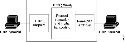
Gateways allow H.323 terminals to communicate with devices that are running other protocols. They provide protocol conversion between the devices that are running different types of protocols. For example, Figure 2 shows a gateway between an H.323 terminal and a non-H.323 terminal.
Figure 2 Gateway Between an H.323 Terminal and an H.320 Terminal
H.323 Proxies
H.323 proxies are special types of gateways that relay H.323 calls to another H.323 endpoint. They can be used to isolate sections of an H.323 network for security purposes, to manage quality of service (QoS), or to perform special application-specific routing tasks.
H.323 Gatekeepers
An H.323 gatekeeper is an H.323 entity on the LAN that provides address translation and that controls access to the LAN for H.323 terminals, gateways, and MCUs.
Gatekeepers are optional nodes that manage endpoints in an H.323 network. The endpoints communicate with the gatekeeper using the RAS protocol.
Endpoints attempt to register with a gatekeeper on startup. When they wish to communicate with another endpoint, they request admission to initiate a call using a symbolic alias for the endpoint, such as an E.164 address or an e-mail address. If the gatekeeper decides that the call can proceed, it returns a destination IP address to the originating endpoint. This IP address may not be the actual address of the destination endpoint, but it may be an intermediate address, such as the address of a proxy or a gatekeeper that routes call signaling.
Note ![]() Although the gatekeeper is an optional H.323 component, it must be included in the network if proxies are used.
Although the gatekeeper is an optional H.323 component, it must be included in the network if proxies are used.
The Cisco gatekeeper provides H.323 call management, including admission control, bandwidth management, and routing services for calls in the network.
The Cisco H.323-compliant Multimedia Conference Manager (MCM) is a subset of gatekeeper functionality available in a special image.
Note ![]() To learn about MCM and other special images, use Cisco Feature Navigator. Access Cisco Feature Navigator at http://www.cisco.com/go/fn. You must have an account on Cisco.com. If you do not have an account or have forgotten your username or password, click Cancel at the login dialog box and follow the instructions that appear.
To learn about MCM and other special images, use Cisco Feature Navigator. Access Cisco Feature Navigator at http://www.cisco.com/go/fn. You must have an account on Cisco.com. If you do not have an account or have forgotten your username or password, click Cancel at the login dialog box and follow the instructions that appear.
Figure 3 Cisco H.323/Gatekeeper Overview

Alternate Gatekeepers
An endpoint that detects the failure of its gatekeeper can safely recover from that failure by utilizing an alternate gatekeeper for future requests, including requests for existing calls. A gateway can only be registered to a single GK at a time. Only one GK is allowed to manage a single zone. The cluster manages up to five similarly configured zones and shares resources between the alternate gatekeepers in the cluster for each zone. You can define up to 100 zones in a single GK.
Alternate Endpoints
A calling endpoint can recover from a call setup failure by sending a setup message to one of the alternate endpoints so that it is possible for a call to finish even if a gateway goes down and the gatekeeper is not yet aware of the problem. Cisco supports a maximum of 20 alternates for each endpoint, and any alternates received through registration, admission, and status protocol (RAS) messages are merged with those entered manually in the gatekeeper command-line interface. If more than 20 alternates are submitted, the total list of alternates reverts back to 20.
GKTMP Messages
The Gatekeeper Transaction Message Protocol (GKTMP) servers can set triggers for disengage request (DRQ) and resource availability indication (RAI) messages. Other messages are extended to contain more parameters for added call control.
Billing Information
The gatekeeper sends detailed call information to a RADIUS distributed client/server system that can be used for billing purposes. RADIUS servers use the vendor-specific attribute (VSA) capability to configure features for individual users.
Least-Cost Routing
Cost and priority fields are included with each remote zone definition, which ensures that the zones with lower cost are given an advantage over zones with higher cost.
Load Balancing
Load balancing allows the gatekeeper to move registered H.323 endpoints to an alternate gatekeeper or to reject new calls and registrations once a certain threshold is met.
Border Elements
Border elements (BE) exchange addressing information and participate in call authorization between the administrative domains. The BEs are often located with a gatekeeper. The BE can reduce the routing information passed though the network by aggregating address information.
Gatekeeper Zones
An H.323 endpoint is an H.323 terminal, gateway, or MCU. An endpoint can call and be called.
H.323 endpoints are grouped into zones. Each zone has one gatekeeper that manages all the endpoints in the zone. A zone is an administrative convenience similar to a Domain Name System (DNS) domain. (Because a zone is, by definition, the area of control of a gatekeeper, the terms "zone name" and "gatekeeper name" are used synonymously in this chapter.)
Note ![]() The maximum number of local zones defined in a gatekeeper should not exceed 100.
The maximum number of local zones defined in a gatekeeper should not exceed 100.
Discovery and Registration
Gateways and gatekeepers communicate using the Registration, Admission, and Status (RAS) protocol for discovery and registration. When endpoints are brought online, they first attempt to discover their gatekeeper. They discover their gatekeeper either by sending multicast a discovery request or by being configured with the address and, optionally, with the name of the gatekeeper and by sending a unicast discovery request. Following successful discovery, each endpoint registers with the gatekeeper. The gatekeeper keeps track of which endpoints are online and available to receive calls.
Cisco IOS Network Address Translation (NAT) supports all H.225 and H.245 message types, including those sent in the RAS protocol.
Call Setup
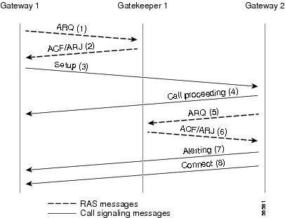
In a typical H.323 call setup scenario, after RAS messages are exchanged, H.225 setup messages are sent over a control channel. For example, in Figure 4, both gateways are registered to the same gatekeeper, and the gatekeeper has chosen direct call signaling.
1. ![]() Gateway 1 (the calling gateway) initiates the admission request (ARQ) (1)/admission confirmation (ACF) (2) exchange with that gatekeeper.
Gateway 1 (the calling gateway) initiates the admission request (ARQ) (1)/admission confirmation (ACF) (2) exchange with that gatekeeper.
2. ![]() The gatekeeper returns the call signaling channel address of Gateway 2 (the called gateway) in the ACF.
The gatekeeper returns the call signaling channel address of Gateway 2 (the called gateway) in the ACF.
3. ![]() Gateway 1 then sends the setup (3) message to Gateway 2 using that transport address.
Gateway 1 then sends the setup (3) message to Gateway 2 using that transport address.
4. ![]() The setup is complete and the call is proceeding (4).
The setup is complete and the call is proceeding (4).
5. ![]() If Gateway 2 wishes to accept the call, it initiates an ARQ (5)/ACF (6) exchange with the gatekeeper.
If Gateway 2 wishes to accept the call, it initiates an ARQ (5)/ACF (6) exchange with the gatekeeper.
6. ![]() The gatekeeper responses with ACF/ARJ (6).
The gatekeeper responses with ACF/ARJ (6).
7. ![]() Gateway 2 sends an alerting (7) message to Gateway 1. (If Gateway 2 receives an admission reject [ARJ] (6) message instead of an ACF message, it sends a release complete message to Gateway 1 instead of the alerting message.)
Gateway 2 sends an alerting (7) message to Gateway 1. (If Gateway 2 receives an admission reject [ARJ] (6) message instead of an ACF message, it sends a release complete message to Gateway 1 instead of the alerting message.)
8. ![]() Gateway 2 responds with the connect (8) messege to Gateway 1
Gateway 2 responds with the connect (8) messege to Gateway 1
Note ![]() An H.245 control channel transport for use in H.245 signalling can send in any of the H.225 messeges: call proceeding, alerting, or connect.
An H.245 control channel transport for use in H.245 signalling can send in any of the H.225 messeges: call proceeding, alerting, or connect.
Figure 4 Both Gateways Registered to the Same Gatekeeper
Fast connect allows endpoints to establish media channels without waiting for a separate H.245 connection to be opened. This streamlines the number of messages that are exchanged and the amount of processing that must be done before endpoint connections can be established. A high-level view of the fast-connect procedures within the H.323 protocol follows:
1. ![]() The calling endpoint transmits a setup message containing the fastStart element that contains a sequence of encoded logical channel structures, each representing a different capability media type for both "send" and "receive" directions.
The calling endpoint transmits a setup message containing the fastStart element that contains a sequence of encoded logical channel structures, each representing a different capability media type for both "send" and "receive" directions.
2. ![]() The called endpoint selects one or more of the media types offered by the calling endpoint for the send and receive directions and returns its selections in a fastStart element in any H.225 message up to and including connect. At this point, the called endpoint must be prepared to receive media along any of the channels it selected.
The called endpoint selects one or more of the media types offered by the calling endpoint for the send and receive directions and returns its selections in a fastStart element in any H.225 message up to and including connect. At this point, the called endpoint must be prepared to receive media along any of the channels it selected.
3. ![]() If H.245 procedures are needed and one or both of the endpoints do not support tunneling, a separate H.245 connection is used.
If H.245 procedures are needed and one or both of the endpoints do not support tunneling, a separate H.245 connection is used.
Fast connect is not explicitly configurable. All H.323 Version 2 VoIP endpoints are capable of initiating or accepting fast-connect calls. It is assumed that the gateway is capable of sending and receiving fast-connect procedures unless its corresponding dial peer has been configured for the Resource Reservation Protocol (RSVP). RSVP means the quality of service is set by the req-qos command to a value other than the default of best-effort. If the dial peer has been configured for RSVP, traditional "slow" connect procedures are followed, and the endpoint neither attempts to initiate fast connect nor responds to a fast-connect request from its peer.
A terminating endpoint can reject fast connect by simply omitting the fastStart element from all H.225 messages up to and including connect. In this case, normal H.245 procedures are followed and a separate H.245 TCP connection is established. So, if an endpoint does not support the fast-connect procedures, normal H.245 procedures are followed. In addition, certain conditions can cause a fast-connect call to fall back to normal H.245 procedures to complete the call.
Once a media connection has been opened (an audio path has been established), either endpoint has the option of switching to H.245 procedures (if they are needed) by using H.245 tunneling, whereby H.245 messages are encapsulated within the h245Control element of H.225 messages.
The dtmf-relay command is the only H.245-cognizant command that can initiate H.245-tunneling procedures from a fast-connect call. If H.245 tunneling is active on the call, switching to a separate H.245 connection is not supported.
A Cisco terminating endpoint accepts a fast-connect request only if a pair of symmetric codecs (codecs that in both directions are equivalent or identical) can be selected from a list that has been offered. The originating endpoint is constrained only by what it can send through the codec (or voice class codec list) associated with the dial peer.
If the Cisco originating endpoint has offered multiple codecs and the terminating endpoint selects a pair of asymmetric (mismatched) codecs, the originating endpoint initiates separate H.245 procedures to correct the asymmetric codec situation.
Fast connect is backward compatible with H.323 Version 1 configurations.
Call Termination
Either gateway may terminate a call in one of the following ways:
1. ![]() Discontinuing transmission of video at the end of a complete picture and then closes all logical channels for video.
Discontinuing transmission of video at the end of a complete picture and then closes all logical channels for video.
2. ![]() Discontinuing transmission of data and then closes all logical channels for data.
Discontinuing transmission of data and then closes all logical channels for data.
3. ![]() Discontinuing transmission of voice and then closes all logical channels for voice.
Discontinuing transmission of voice and then closes all logical channels for voice.
4. ![]() Transmitting the H.245 endSessionCommand message in the H.245 control channel, indicating to the far end that it wishes to disconnect the call and then discontinues H.245 message transmission.
Transmitting the H.245 endSessionCommand message in the H.245 control channel, indicating to the far end that it wishes to disconnect the call and then discontinues H.245 message transmission.
5. ![]() Waiting to receive the endSessionCommand message from the other gateway and then closes the H.245 control channel.
Waiting to receive the endSessionCommand message from the other gateway and then closes the H.245 control channel.
6. ![]() Sending a release complete message if the call signaling channel is open and the channel is closed.
Sending a release complete message if the call signaling channel is open and the channel is closed.
7. ![]() Clearing the call by using the procedures defined below.
Clearing the call by using the procedures defined below.
An endpoint receiving an endSessionCommand message without first having transmitted it carries out steps 1 and 7 above, except that in Step 5, the gateway waits for the endSessionCommand message from the first endpoint.
Terminating a call may not terminate a conference; a conference may be explicitly terminated using an H.245 message (dropConference). In this case, the gateways wait for the multipoint controller to terminate the calls as described.
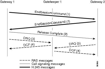
In networks that contain a gatekeeper, the gatekeeper needs to know about the release of bandwidth. After performing steps 1 to 6 in the preceding section, each endpoint transmits an H.225 disengage request (DRQ) message (3) to its gatekeeper as shown in Figure 5. The gatekeeper responds with a disengage confirm (DCF) message (4). After sending the DRQ message, the endpoints do not send further unsolicited information request response (IRR) messages that relate to that call to the gatekeeper. At this point, the call is terminated. Figure 5 shows the direct call model. The DRQ and DCF messages are sent on the RAS channel.
Cisco IOS H.323 gateways will terminate a call if a TCP connection is closed while the call is in progress, or if a TCP connection error is detected when signaling message are sent or received.
Figure 5 Call Termination Direct Call Model
Security
Security for RAS protocol signaling between H.323 endpoints and gatekeepers is enhanced in H.323 Version 2 software by including secure endpoint registration of the Cisco gateway to the Cisco gatekeeper and secure per-call authentication. In addition, it provides for the protection of specific messages related to Open Settlement Protocol (OSP) and to other messages as required via encryption tokens. The authentication type is "password with hashing" as described in the ITU H.235 specifications. Specifically, the encryption method is to use the MD5 algorithm, with password hashing. This functionality is provided by the security token required-for command on the gatekeeper and the security password command on the gateway.
The gatekeeper can interact with a RADIUS security server to perform the authentications. The gateway can also authenticate an external application by using the Gatekeeper Transaction Message Protocol (GKTMP) application programming interface (API).
Per-call authentication is accomplished by validating account and pin numbers that are entered by the user connected to the calling gateway by using an IVR prompt.
The security mechanisms described above require the gateway and gatekeeper clocks to be synchronized within 30 seconds of each other by using a Network Time Protocol (NTP) server.
Additional References
The following sections provide references related to H.323.
Related Documents
Standards
MIBs
|
|
|
|---|---|
• |
To locate and download MIBs for selected platforms, Cisco IOS releases, and feature sets, use Cisco MIB Locator found at the following URL: http://www.cisco.com/go/mibs |
RFCs
|
|
|
|---|---|
RFC 2833 |
RTP Payload for DTMF Digits, Telephony Tones and Telephony Signals |
 Feedback