- Customer Business Objectives
- Proposed Solution: Interdomain Multicast Using MSDP
- Implementation of Proposed Solution: Interdomain Multicast Using MSDP
Interdomain Multicast Solutions Using MSDP
Version History
|
|
|
|
|---|---|---|
1 |
11/2/2000 |
This document was created. |
2 |
1/03/2001 |
The following sections were updated: • • |
3 |
3/22/2001 |
The title of this document changed from "Interdomain Multicast Solutions" to "Interdomain Multicast Solutions Using MSDP." |
Demand for IP multicast services to extend applications across Internet service provider (ISP) network boundaries to a wider audience is growing. To meet this need, sophisticated protocols such as Protocol Independent Multicast sparse mode (PIM-SM), Multiprotocol Border Gateway Protocol (MBGP), and Multicast Source Discovery Protocol (MSDP) are available in Cisco IOS software that provide solutions for successfully implementing native interdomain multicast service.
This solutions document describes how four hypothetical ISPs implement interdomain multicast among them using PIM-SM, MBGP, and MSDP. Various interdomain multicast implementation trade-offs are discussed and a preferred network design is presented that outlines "best practices" for ISP deployment of IP multicast. The multicast solutions presented in this document are based on actual customer situations. These solutions were tested and verified in a lab environment and have been deployed in the field. There are alternative ways to implement ISP interdomain multicast that are not discussed in this guide.
The scope of this solutions document is to describe basic design and deployment of an interdomain multicast network. It does not discuss in detail the general operation of the protocols associated with developing interdomain multicast networks such as PIM-SM, MBGP, and MSDP.
This document contains the following sections:
•![]() Proposed Solution: Interdomain Multicast Using MSDP
Proposed Solution: Interdomain Multicast Using MSDP
•![]() Implementation of Proposed Solution: Interdomain Multicast Using MSDP
Implementation of Proposed Solution: Interdomain Multicast Using MSDP
Customer Business Objectives
The customer business objectives of each of the four hypothetical ISPs discussed in this document are as follows:
•![]() To leverage existing network infrastructure to create additional incremental revenue streams and provide value-added services to customers by enabling interdomain multicast.
To leverage existing network infrastructure to create additional incremental revenue streams and provide value-added services to customers by enabling interdomain multicast.
•![]() To efficiently deliver scalable real-time content (for example, high-quality video and audio, market data, and distance learning) from content providers to subscribers by enabling IP multicast.
To efficiently deliver scalable real-time content (for example, high-quality video and audio, market data, and distance learning) from content providers to subscribers by enabling IP multicast.
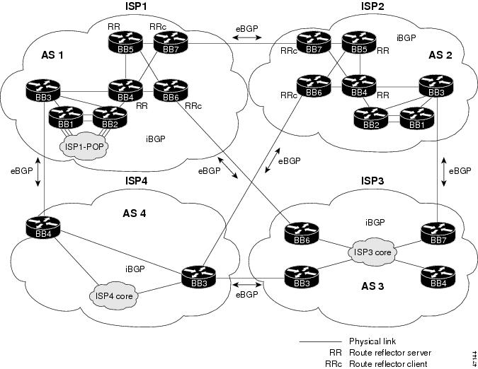
Initial Interdomain Multicast Network Topology
The hypothetical interdomain multicast network scenario used in this solutions document has an ISP backbone characteristic of some of the largest ISPs. Figure 1 shows the logical connections between four typical ISP domains in which interdomain multicast will be deployed. Each ISP has Border Gateway Protocol (BGP) peering and its own autonomous system (AS) established. As shown in Figure 1, ISP1 and ISP2 have implemented route reflectors for their internal BGP peering sessions. The design of each ISP multicast network topology is dependent on the individual requirements of the ISP.

Note ![]() The solutions presented in this document are based on a hypothetical interdomain ISP environment. All the IP addresses and configuration in this document are provided for illustrative purposes only.
The solutions presented in this document are based on a hypothetical interdomain ISP environment. All the IP addresses and configuration in this document are provided for illustrative purposes only.
Figure 1 Logical Connections of a Typical ISP Interdomain Environment
Proposed Solution: Interdomain Multicast Using MSDP
This section contains the following subsections:
•![]() Overall Interdomain Multicast Solution Overview
Overall Interdomain Multicast Solution Overview
•![]() Overall Interdomain Multicast Prerequisites
Overall Interdomain Multicast Prerequisites
•![]() Overall Interdomain Multicast Network Topology
Overall Interdomain Multicast Network Topology
•![]() Overall Interdomain Multicast Benefits
Overall Interdomain Multicast Benefits
•![]() Overall Interdomain Multicast Ramifications
Overall Interdomain Multicast Ramifications
Overall Interdomain Multicast Solution Overview
The strategy for implementing interdomain multicast among the four ISPs has the following three parts:
•![]() Part 1: Overall Intradomain Multicast Strategy
Part 1: Overall Intradomain Multicast Strategy
•![]() Part 2: Overall Interdomain Multicast Strategy
Part 2: Overall Interdomain Multicast Strategy
•![]() Part 3: Implementation Strategy for Connecting Customers into Infrastructure
Part 3: Implementation Strategy for Connecting Customers into Infrastructure
Note ![]() The multicast solutions in this document were tested with valid IP addresses. In the example configurations provided in the following sections, the first octet of these reserved IP addresses has been replaced with the letter "J" or the letter "K" for privacy reasons. The letter "J" always represents one unique number, and the letter "K" always represents one unique number that is different from "J."
The multicast solutions in this document were tested with valid IP addresses. In the example configurations provided in the following sections, the first octet of these reserved IP addresses has been replaced with the letter "J" or the letter "K" for privacy reasons. The letter "J" always represents one unique number, and the letter "K" always represents one unique number that is different from "J."
The example configurations are intended for illustrative purposes only. The letters "J" and "K" must be replaced with valid numbers when these IP addresses are configured in an actual network.
Part 1: Overall Intradomain Multicast Strategy
Before the four ISPs in Figure 1 can deploy multicast services between each other, they must each implement multicast within their own networks. PIM-SM is the multicast forwarding protocol used in these intradomain multicast scenarios. PIM-SM was originally described in RFC 2362. This RFC is being revised.
This section contains the following subsections:
•![]() PIM
PIM
•![]() Overall Intradomain Multicast Configuration Tasks
Overall Intradomain Multicast Configuration Tasks
PIM
PIM gets its name from the fact that it is IP routing protocol independent. PIM can leverage whichever unicast routing protocols are used to populate the unicast routing table, including Enhanced Interior Gateway Routing Protocol (EIGRP), Open Shortest Path First (OSPF), BGP, and static routes. PIM uses this unicast routing information to perform the multicast forwarding function, therefore it is IP protocol independent. Although PIM is called a multicast routing protocol, it actually uses the unicast routing table to perform the Reverse Path Forwarding (RPF) check function instead of building up a completely independent multicast routing table. Unlike other routing protocols, PIM does not send and receive multicast routing updates between routers.
PIM-SM
PIM-SM uses a pull model to deliver multicast traffic. Only network segments with active receivers that have explicitly requested the data will be forwarded the traffic. PIM-SM uses a shared tree to distribute information about active sources. Depending on the configuration options, the traffic can remain on the shared tree or switch over to an optimized source distribution tree. The latter is the default behavior for PIM-SM on Cisco routers. The traffic starts to flow down the shared tree, and then routers along the path determine if there is a better path to the source. If a more direct path exists, the last hop router (router closest to the receiver) sends a join message toward the source and then reroutes the traffic along this path.
Because PIM-SM uses shared trees (at least initially), it requires the use of a rendezvous point (RP). The RP must be administratively configured in the network. Sources register with the RP and then data is forwarded down the shared tree to the receivers. If the shared tree is not an optimal path between the source and the receiver, the routers dynamically create a source tree and stop traffic from flowing down the shared tree. This behavior is the default behavior in Cisco IOS software.
PIM-SM scales well to a network of any size, including those with WAN links. The explicit join mechanism will prevent unwanted traffic from flooding the WAN links.
Overall Intradomain Multicast Configuration Tasks
To configure intradomain multicast within an ISP, perform the following general configuration tasks:
Step 1 ![]() Configure multicast globally.
Configure multicast globally.
To configure multicast globally, use the following two global configuration commands:
•![]() ip multicast-routing [distributed]
ip multicast-routing [distributed]
This command enables IP multicast forwarding. If disabled, group addressed IP packets of which the router is not a member will be discarded. The default value is IP multicast routing disabled. (The ip multicast-routing command was introduced in Cisco IOS Release 10.2.)
The distributed keyword enables distributed fast switching for the router. The ip mroute-cache distributed interface command enables individual interfaces for distributed fast switching. The distributed keyword is currently supported on the Cisco 7500 and 12000 router series. (The distributed keyword was introduced in Cisco IOS Release 11.1(20)CC.)
•![]() ip multicast multipath
ip multicast multipath
This command enables different reverse path forwarding (RPF) interfaces to be used for each multicast route that matches the same unicast route prefix if and only if there are equal cost paths for the route prefix. The load sharing is only done on a per-(S, G) basis. (The ip multicast multipath command is supported in Cisco IOS Releases 12.0, 12.0 S, and 12.0 T.)
Step 2 ![]() Configure multicast on the interfaces.
Configure multicast on the interfaces.
To configure multicast on the interfaces, use the following two interface configuration commands:
•![]() ip pim sparse-mode
ip pim sparse-mode
This command enables the PIM multicast routing protocol on the interface. It configures the interface to operate in sparse mode. A sparse mode interface is used only for multicast forwarding if a join message is received from a downstream router or directly connected members are on the interface. (The ip pim sparse-mode command was introduced in Cisco IOS Release 10.2.)
•![]() ip mroute-cache [distributed]
ip mroute-cache [distributed]
This command configures IP multicast fast switching. If fast switching is disabled on an incoming interface for a multicast routing table entry, the packet is sent at the process level for all interfaces in the outgoing interface list. If fast switching is disabled on an outgoing interface for a multicast routing table entry, the packet is process level-switched for that interface but may be fast-switched for other interfaces in the outgoing interface list. The default setting is that all interfaces are multicast fast switched. (The ip mroute-cache command was introduced in Cisco IOS Release 11.0.)
The distributed keyword enables the interface to perform distributed fast switching on incoming packets. This command applies to the configuration of the physical interface and not to subinterfaces.
Once this command is configured on the interface, all packets coming in this interface are distributed-switched. The ip route-cache distributed command should be configured before this command is configured on a Cisco 7500 series router (and not on the Cisco 12000 series Gigabit Switch Router). (The distributed keyword was introduced in Cisco IOS Release 11.1(20)CC.)
Note ![]() We recommend that you configure the ip route-cache distributed command on all platforms that support it.
We recommend that you configure the ip route-cache distributed command on all platforms that support it.
Step 3 ![]() Select the router to be RP.
Select the router to be RP.
The actual location of the RP should not be a critical decision. Choose any location that is centrally accessible throughout the ISP domain.
Choose an IP address for the RP that can be given out to customers and be advertised to other domains. Typically, a unique IP address with a 32-bit mask is assigned to a loopback address, and this address is used for the RP.
Step 4 ![]() Configure the RP statically on each router in the network.
Configure the RP statically on each router in the network.
To configure the RP, use the ip pim rp-address rp-address access-list global configuration command.
This command configures the PIM rendezvous point (RP) address for a particular group. The RP address is used by first hop routers to send register packets on behalf of source multicast hosts. The RP address is also used by routers on behalf of multicast hosts that want to become members of a group. These routers send join and prune messages toward the RP. A single RP can be configured for all multicast groups or a subset of the Class D address range as described by the access list pointer. (The ip pim rp-address command was introduced in Cisco IOS Release 10.2.)
Part 2: Overall Interdomain Multicast Strategy
To successfully deploy interdomain multicast among the four ISPs, each ISP will use the following protocols:
•![]() Multiprotocol Border Gateway Protocol (MBGP) for interdomain routing.
Multiprotocol Border Gateway Protocol (MBGP) for interdomain routing.
•![]() Multicast Source Discovery Protocol (MSDP) for interdomain source discovery.
Multicast Source Discovery Protocol (MSDP) for interdomain source discovery.
MBGP and MSDP connect PIM-SM domains. MBGP is a policy-based interdomain routing protocol for choosing best paths through an IP internetwork. MSDP enables RPs from different domains to exchange information about active sources.
This section contains the following subsections:
•![]() MBGP
MBGP
•![]() MSDP
MSDP
•![]() Overall Interdomain Multicast Configuration Tasks
Overall Interdomain Multicast Configuration Tasks
MBGP
MBGP provides a method for providers to distinguish which route prefixes they will use for performing multicast RPF checks. The RPF check is the fundamental mechanism that routers use to determine the paths that multicast forwarding trees will follow and to successfully deliver multicast content from sources to receivers.
MBGP is described in RFC 2283, Multiprotocol Extensions for BGP-4. Because MBGP is an extension of BGP, it contains all the administrative machinery that providers and customers desire in their interdomain routing environment, including all the inter-AS tools to filter and control routing (for example, route maps). Therefore, any network utilizing internal BGP (iBGP) or external BGP (eBGP) can use MBGP to apply the multiple policy control knobs familiar in BGP to specify routing (and thereby forwarding) policy for multicast.
Two path attributes, MP_REACH_NLRI and MP_UNREACH_NLRI, were introduced in BGP4. These new attributes create a simple way to carry two sets of routing information—one for unicast routing and one for multicast routing. The routes associated with multicast routing are used for RPF checking at the interdomain borders.
The main advantage of MBGP is that an internet can support noncongruent unicast and multicast topologies. When the unicast and multicast topologies are congruent, MBGP can support different policies for each. MBGP provides a scalable policy-based interdomain routing protocol.
MSDP
In the PIM-SM model, multicast sources and receivers must register with their local RP. Actually, the router closest to the sources or receivers registers with the RP, but the key point to note is that the RP knows about all the sources and receivers for any particular group. RPs in other domains have no way of knowing about sources located in other domains. MSDP is an elegant way to solve this problem.
MSDP is a mechanism that allows RPs to share information about active sources. RPs know about the receivers in their local domain. When RPs in remote domains hear about the active sources, they can pass on that information to their local receivers and multicast data can then be forwarded between the domains. A useful feature of MSDP is that it allows each domain to maintain an independent RP that does not rely on other domains, but it does enable RPs to forward traffic between domains. PIM-SM is used to forward the traffic between the multicast domains.
The RP in each domain establishes an MSDP peering session using a TCP connection with the RPs in other domains or with border routers leading to the other domains. When the RP learns about a new multicast source within its own domain (through the normal PIM register mechanism), the RP encapsulates the first data packet in a Source-Active (SA) message and sends the SA to all MSDP peers. The SA is forwarded by each receiving peer using a modified RPF check, until the SA reaches every MSDP router in the interconnected networks—theoretically the entire multicast internet. If the receiving MSDP peer is an RP, and the RP has a (*, G) entry for the group in the SA (there is an interested receiver), the RP creates (S, G) state for the source and joins to the shortest path tree for the source. The encapsulated data is decapsulated and forwarded down the shared tree of that RP. When the packet is received by the last hop router of the receiver, the last hop router also may join the shortest path tree to the source. The MSDP speaker periodically sends SAs that include all sources within the own domain of the RP.
Overall Interdomain Multicast Configuration Tasks
To configure interdomain multicast, perform the following general configuration tasks:
Step 1 ![]() Configure MBGP to exchange multicast routing information.
Configure MBGP to exchange multicast routing information.
a. ![]() Configure MBGP peering sessions.
Configure MBGP peering sessions.
The command syntax used to configure MBGP varies depending on which Cisco IOS software release is running on the router.
•![]() For Cisco IOS Release 12.0 S, use the following BGP router configuration commands:
For Cisco IOS Release 12.0 S, use the following BGP router configuration commands:
–![]() neighbor ip-address remote-as number [nlri {unicast | multicast}]
neighbor ip-address remote-as number [nlri {unicast | multicast}]
This command configures a BGP peer and associated AS number. If the multicast keyword only is supplied, multicast Network Layer Reachability Information (NLRI) is sent only to the neighbor. However, if the unicast keyword only is supplied, unicast NLRI is sent only to the neighbor. Both keywords may be supplied, which indicates that the neighbor will be sent both types of routes. Unicast NLRI will be sent in the conventional encoding and the multicast NLRI will be sent in the MP_REACH and MP_UNREACH path attributes. The default is to send unicast NLRI only. This version of BGP will negotiate NLRI in the Capabilities Option of the Open message. Therefore, both sides of a BGP connection must be configured consistently with respect to NLRI or the MBGP peering session will not be established.
–![]() neighbor peer-group-name peer-group [nlri {unicast | multicast}]
neighbor peer-group-name peer-group [nlri {unicast | multicast}]
This command configures the peer group to support either unicast NLRI, multicast NLRI, or both. Supplying both the unicast and multicast keywords indicates that both NLRIs are sent. The default value is unicast only.
–![]() network network-number [mask network-mask] [nlri {unicast | multicast}]
network network-number [mask network-mask] [nlri {unicast | multicast}]
This command determines if the network in the AS should be injected into the BGP unicast routing information base (RIB) or the MBGP multicast RIB. If both the unicast and multicast keywords are specified, the network is injected in both RIBs. If the multicast keyword only is specified, the network is injected in the multicast RIB only. The default is unicast only.
•![]() For Cisco IOS Release 12.0 S, use the following MBGP route map configuration commands:
For Cisco IOS Release 12.0 S, use the following MBGP route map configuration commands:
–![]() match nlri {unicast | multicast}
match nlri {unicast | multicast}
The route-map criteria can be based on the unicast or multicast RIB (or both). If the multicast RIB entry is being processed for a route map with the match nlri multicast command, then the route-map condition yields TRUE, likewise for the unicast corollary. If both the unicast and multicast keywords are specified, then either RIB entry being processed yields TRUE. The default value is both unicast and multicast.
This command can be used in conjunction with the neighbor ip-address route-map map-name in command so that you can use one route-map reference to describe filtering policies for different NLRI types.
–![]() set nlri {unicast | multicast}
set nlri {unicast | multicast}
If the route-map match criteria are met, decide if the route should be injected into the unicast or multicast RIB. If both the unicast and multicast keywords are specified, the route is injected into both RIBs and advertised as a separate NLRI in a BGP Update message. If only the multicast keyword is specified, the route is injected only into the multicast RIB. The default value is unicast only in all cases except when this route map is referenced by a neighbor ip-address route-map map-name out command. This route map configuration command is used when referencing a route map by various router configuration commands (that is, redistribute, aggregate-address, and neighbor outbound route-map references).
This command can be used in conjunction with the neighbor ip-address default-originate route-map map-name command. If the set nlri command is supplied in the route map referenced by the neighbor command, the multicast default route can be generated independently of the unicast default route.
•![]() For Cisco IOS Release 12.0 T or 12.1, use the following MBGP address family configuration commands:
For Cisco IOS Release 12.0 T or 12.1, use the following MBGP address family configuration commands:
–![]() address-family ipv4 multicast
address-family ipv4 multicast
This command places the router in address family configuration mode. The multicast keyword specifies that multicast NLRI information is used with neighbors and networks that are explicitly configured under the address-family ipv4 multicast command section in the configuration. Routing information for address family IPv4 is advertised by default when you configure a BGP routing session using the neighbor remote-as command unless you execute the no bgp default ipv4-activate command.
–![]() neighbor {ip-address | peer-group-name} activate
neighbor {ip-address | peer-group-name} activate
This command enables or disables the exchange of information with a neighboring router. The exchange of addresses with neighbors is enabled by default for the IPv4 address family. For all other address families, you must explicitly activate the neighbor in the appropriate address family section.
A Cisco Application Note discussing the changes in MBGP commands between Cisco IOS Release 12.0 S, 12.0 T, and 12.1 can be found at the following location:
http://www.cisco.com/warp/public/cc/pd/iosw/prodlit/mcb12_an.htm
Note ![]() We strongly recommend that you use the same IP address for BGP and MSDP peering sessions. This address is typically a unique IP address with a 32-bit mask assigned on a loopback interface.
We strongly recommend that you use the same IP address for BGP and MSDP peering sessions. This address is typically a unique IP address with a 32-bit mask assigned on a loopback interface.
b. ![]() Verify that MBGP multicast routes are working properly.
Verify that MBGP multicast routes are working properly.
To verify that MBGP multicast routes are working properly, use the following EXEC commands:
–![]() show ip bgp neighbors
show ip bgp neighbors
–![]() show ip mbgp
show ip mbgp
Step 2 ![]() Configure MSDP peering sessions.
Configure MSDP peering sessions.
a. ![]() Select an IP address.
Select an IP address.
Select an IP address that you will use for MSDP peering sessions. This address is usually a loopback address that is the same as the BGP sessions.
b. ![]() Configure peering sessions.
Configure peering sessions.
Configure peering sessions from the local RP to the RP in another ISP using the ip msdp peer {peer-name | peer-address} [connect-source type number] global configuration command. This command configures an MSDP peer. If you also have a BGP peering session with this MSDP peer, you should use the same IP address for MSDP as you do for BGP. The connect-source keyword is used to supply a source IP address for the TCP connection. The primary address configured on the interface is used.
Step 3 ![]() Configure recommended SA filters.
Configure recommended SA filters.
The following global configuration commands configure outgoing or incoming filter lists for Source-Active (SA) messages sent to an MSDP peer:
•![]() ip msdp sa-filter out {peer-address | peer-name} [list access-list] [route-map map-name]
ip msdp sa-filter out {peer-address | peer-name} [list access-list] [route-map map-name]
•![]() ip msdp sa-filter in {peer-address | peer-name} [list access-list] [route-map map-name]
ip msdp sa-filter in {peer-address | peer-name} [list access-list] [route-map map-name]
The default setting is that all SA messages received are forwarded to the peer. The access-list argument is an extended access list that can describe source/group pairs to pass through the filter. If the route-map map-name keyword and argument is specified, you can filter based on match criteria in the map-name argument. If all match criteria are true, a permit from the route map passes routes through the filter. A deny filters routes. If both keywords are used, all conditions must be true to pass or filter any (S, G) in outgoing SA messages. If neither keyword if specified, all source/group pairs are filtered.
A document describing recommended SA filters can be found at the following location:
http://www.cisco.com/warp/public/105/49.html
Step 4 ![]() Configure SA caching.
Configure SA caching.
We recommend that you enable the SA caching feature. To configure the SA caching, use the ip msdp cache-sa-state command. This command indicates to the router that SA state should be cached for faster service.
Step 5 ![]() Verify that MSDP peers are working properly.
Verify that MSDP peers are working properly.
To verify that MSDP peers are working properly, use the following EXEC commands:
•![]() show ip msdp peer
show ip msdp peer
•![]() show ip msdp sa-cache
show ip msdp sa-cache
Step 6 ![]() Configure multicast borders appropriately.
Configure multicast borders appropriately.
To configure the multicast border, use the following two interface configuration commands:
•![]() ip multicast boundary access-list
ip multicast boundary access-list
This command configures an administratively scoped boundary on the interface for multicast group addresses in the range defined by the simple IP access list access-list argument. No multicast data packets will be allowed to flow across the boundary from either direction, allowing reuse of the same multicast group address in different administrative domains. (The multicast address range from 239.0.0.0 to 239.255.255.255 is designated as the administratively scoped addresses.) For example, to configure a boundary for all administratively scoped addresses, use the following commands:
access-list 1 deny 239.0.0.0 0.255.255.255
access-list 1 deny 224.0.1.40
access-list 1 deny 224.0.1.39
access-list 1 permit 224.0.0.0 15.255.255.255
interface ethernet 0
ip multicast boundary 1
•![]() ip pim bsr-border
ip pim bsr-border
This command configures the interface to be the PIM domain border. Bootstrap messages will not be able to pass through this border in either direction. The PIM domain border effectively partitions the network into regions using different RPs that are configured using the bootstrap router feature. No other PIM messages are dropped by this domain border setup. Please also note that this command does not set up any multicast boundaries. (The ip pim border command was introduced in Cisco IOS Release 11.1(20)CC. This command was replaced with the ip pim bsr-border command in Cisco IOS Release 12.0(7.1).)
Part 3: Implementation Strategy for Connecting Customers into Infrastructure
Now that all four ISPs in Figure 1 can share multicast traffic through interdomain routing, the individual ISPs can connect customers into their infrastructure. The following three scenarios describe the types of customers that may want to connect to an ISP to receive multicast traffic:
•![]() Multicast customer with external RP:
Multicast customer with external RP:
–![]() Customer does not run MBGP
Customer does not run MBGP
–![]() Customer does not have its own RP
Customer does not have its own RP
This customer does not have its own AS. It does not want to have or manage its own multicast domain. It only wants multicast service. The customer will configure its routers to point to the RP of the ISP.
•![]() Multicast customer with internal RP and without MBGP:
Multicast customer with internal RP and without MBGP:
–![]() Customer does not run MBGP
Customer does not run MBGP
–![]() Customer has its own RP
Customer has its own RP
This customer does not have its own AS, but is serious enough about multicast that it want its own RP for its local applications. The customer RP would use MSDP to peer with the ISP RP. The customer can run Auto-RP in its domain, and the ISP would filter Auto-RP on its borders.
•![]() Multicast customer with internal RP and MBGP:
Multicast customer with internal RP and MBGP:
–![]() Customer runs MBGP
Customer runs MBGP
–![]() Customer has its own RP
Customer has its own RP
This situation is the same peering arrangement as connecting to another ISP. All of the same border precautions should be taken.
Overall Interdomain Multicast Prerequisites
Before implementing interdomain multicast among the four ISPs in Figure 1, the individual ISPs must establish the following prerequisites:
•![]() An IP address allocation plan
An IP address allocation plan
•![]() BGP peering arrangements with the other ISPs
BGP peering arrangements with the other ISPs
•![]() Customer connections
Customer connections
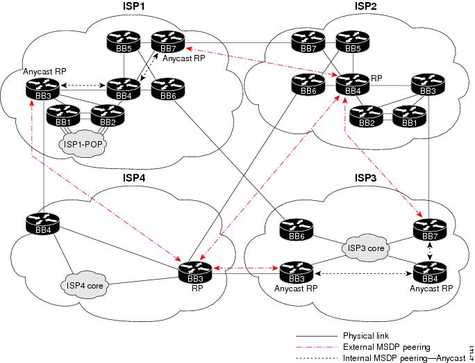
Overall Interdomain Multicast Network Topology
Figure 2 and Figure 3 show the MBGP and MSDP peering sessions established among the four ISPs in which interdomain multicast is being deployed.
Figure 2 MBGP Peering
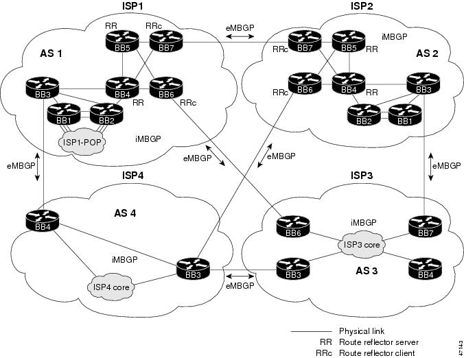
Figure 3 MSDP Peering
Overall Interdomain Multicast Benefits
The benefits of using PIM-SM, MBGP, and MSDP to implement interdomain multicast are as follows:
•![]() Allows an ISP to maintain all routing information needed to determine best paths through the network in its own local RP, which reduces how much each ISP must rely on other ISP networks and gives it greater control over its own customer service levels. This benefit also conserves network capacity.
Allows an ISP to maintain all routing information needed to determine best paths through the network in its own local RP, which reduces how much each ISP must rely on other ISP networks and gives it greater control over its own customer service levels. This benefit also conserves network capacity.
•![]() Enables an ISP to offer interdomain IP multicast services to its customers. This benefit allows content providers to efficiently deliver their products to consumers (for example, applications such as interactive gaming, distance learning, and market data).
Enables an ISP to offer interdomain IP multicast services to its customers. This benefit allows content providers to efficiently deliver their products to consumers (for example, applications such as interactive gaming, distance learning, and market data).
•![]() Offers a service provider the ability to maintain its own RPs while also having knowledge of active sources in other domains. It can now set up certain security measures that previously were not possible. For example, a service provider could filter traffic from certain sources or domains. MSDP allows service providers to have a central point to control the filtering of incoming and outgoing multicast data streams.
Offers a service provider the ability to maintain its own RPs while also having knowledge of active sources in other domains. It can now set up certain security measures that previously were not possible. For example, a service provider could filter traffic from certain sources or domains. MSDP allows service providers to have a central point to control the filtering of incoming and outgoing multicast data streams.
Overall Interdomain Multicast Ramifications
The ramifications for using PIM-SM, MBGP, and MSDP to implement interdomain multicast are as follows:
•![]() Multicast forwarding state must be maintained in the router. This situation uses additional memory resources in the router.
Multicast forwarding state must be maintained in the router. This situation uses additional memory resources in the router.
•![]() Routers that act as an RP or MSDP peer may experience an additional load on CPU resources.
Routers that act as an RP or MSDP peer may experience an additional load on CPU resources.
Implementation of Proposed Solution: Interdomain Multicast Using MSDP
This section describes implementing intradomain and interdomain multicast and connecting customers into the infrastructure of an ISP for scenarios described in the following subsections:
Note ![]() The multicast solutions in this document were tested with valid IP addresses. In the example configurations provided in the following sections, the first octet of these reserved IP addresses has been replaced with the letter "J" or the letter "K" for privacy reasons. The letter "J" always represents one unique number, and the letter "K" always represents one unique number that is different from "J."
The multicast solutions in this document were tested with valid IP addresses. In the example configurations provided in the following sections, the first octet of these reserved IP addresses has been replaced with the letter "J" or the letter "K" for privacy reasons. The letter "J" always represents one unique number, and the letter "K" always represents one unique number that is different from "J."
The example configurations are intended for illustrative purposes only. The letters "J" and "K" must be replaced with valid numbers when these IP addresses are configured in an actual network.
Note ![]() The example configurations provided in the following sections use boldface text to indicate pertinent configuration commands used for deploying the IP multicast solutions described in this document.
The example configurations provided in the following sections use boldface text to indicate pertinent configuration commands used for deploying the IP multicast solutions described in this document.
ISP2 Scenario
This section contains the following subsections:
•![]() ISP2—Implementing Intradomain Multicast
ISP2—Implementing Intradomain Multicast
•![]() ISP2—Implementing Interdomain Multicast
ISP2—Implementing Interdomain Multicast
•![]() ISP2—Connecting Customers into Infrastructure
ISP2—Connecting Customers into Infrastructure
ISP2—Implementing Intradomain Multicast
This section contains the following subsections:
•![]() ISP2—Intradomain Multicast Strategy
ISP2—Intradomain Multicast Strategy
•![]() ISP2—Intradomain Multicast Network Topology
ISP2—Intradomain Multicast Network Topology
•![]() ISP2—Intradomain Multicast Benefits
ISP2—Intradomain Multicast Benefits
•![]() ISP2—Intradomain Multicast Ramifications
ISP2—Intradomain Multicast Ramifications
•![]() ISP2—Intradomain Multicast Configuration Summary
ISP2—Intradomain Multicast Configuration Summary
ISP2—Intradomain Multicast Strategy
ISP2 is a new, relatively small ISP that wants to implement the simplest multicast design. ISP2 is not concerned about advertising all of its internal IP addresses to other ISPs. Therefore, ISP2 implemented a single static RP at the core of its network. The RP is the same router that will peer with other ISPs, and its address is given out to customers.
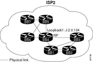
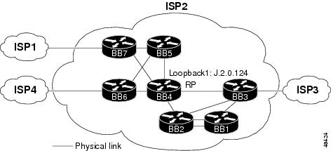
ISP2—Intradomain Multicast Network Topology
Figure 4 shows the intradomain multicast network diagram for ISP2.
Figure 4 Network Diagram for ISP2—Intradomain Multicast
ISP2—Intradomain Multicast Benefits
The benefits of deploying the ISP2 multicast network are as follows:
•![]() The network topology is a simple multicast implementation.
The network topology is a simple multicast implementation.
•![]() The topology creates a deterministic network that is easy to troubleshoot.
The topology creates a deterministic network that is easy to troubleshoot.
ISP2—Intradomain Multicast Ramifications
The ramifications of deploying the ISP2 multicast network are as follows:
•![]() No redundancy—If the RP router were to fail, all new requests for multicast service would also fail.
No redundancy—If the RP router were to fail, all new requests for multicast service would also fail.
•![]() No load sharing—All PIM joins must be serviced by a single RP. Under extreme and unlikely circumstances, this situation may have a performance impact on the router acting as the RP.
No load sharing—All PIM joins must be serviced by a single RP. Under extreme and unlikely circumstances, this situation may have a performance impact on the router acting as the RP.
ISP2—Intradomain Multicast Configuration Summary
The following is a summary of the tasks that were performed to configure the devices in ISP2 for intradomain multicast:
Step 1 ![]() Configure multicast globally.
Configure multicast globally.
The following sample configuration, taken from the configuration file for the ISP2BB4 router, shows how to configure multicast globally on a router. Multicast is configured on all ISP2 routers.
ip multicast-routing distributed
Step 2 ![]() Configure multicast on the interfaces.
Configure multicast on the interfaces.
The following sample configuration shows how to configure multicast on the interfaces of the ISP2BB4 router. Multicast is configured on the interfaces of all the ISP2 routers.
interface POS0/0
ip pim sparse-mode
ip mroute-cache distributed
interface POS2/0
ip pim sparse-mode
ip mroute-cache distributed
interface POS3/0
ip pim sparse-mode
ip mroute-cache distributed
interface GigabitEthernet4/0
ip mroute-cache distributed
interface GigabitEthernet4/0.430
ip pim sparse-mode
interface GigabitEthernet4/0.440
ip pim sparse-mode
interface POS5/0
ip pim sparse-mode
ip mroute-cache distributed
interface POS6/0
ip pim sparse-mode
ip mroute-cache distributed
Note ![]() The ip mroute-cache distributed command must be configured on the main Gigabit Ethernet interface. It is not allowed on subinterfaces.
The ip mroute-cache distributed command must be configured on the main Gigabit Ethernet interface. It is not allowed on subinterfaces.
Step 3 ![]() Select the router to be RP.
Select the router to be RP.
The ISP2BB4 router was selected as the RP because of its central location in the ISP2 network. The following sample configuration shows how a unique IP address with a 32-bit mask is configured on the loopback interface of the RP (ISP2BB4):
interface Loopback1
ip address J.2.0.124 255.255.255.255
ip pim sparse-mode
ip mroute-cache distributed
no shut
Step 4 ![]() Configure the RP statically on each router in ISP2.
Configure the RP statically on each router in ISP2.
The following sample configuration shows how to configure the RP address on each router in ISP2:
ip pim rp-address J.2.0.124
Step 5 ![]() Restrict available multicast groups from using 232/24. (Optional)
Restrict available multicast groups from using 232/24. (Optional)
Source Specific Multicast (SSM) will use the 232.0.0.0 through 232.255.255.255 address range for specific well-known sources. This address range will not require the use of an RP. The following sample configuration shows how to restrict the RP from allowing sources to register sources in this range. These statements need to be configured only on the RP.
ip pim accept-register list no-ssm-range
ip access-list extended no-ssm-range
deny ip any 232.0.0.0 0.255.255.255
permit ip any any
For the device characteristics and complete configuration files of the devices in ISP2, see the "ISP2—Device Characteristics and Complete Configuration Files" section of this document.
ISP2—Implementing Interdomain Multicast
This section contains the following subsections:
•![]() ISP2—Interdomain Multicast Network Topology
ISP2—Interdomain Multicast Network Topology
•![]() ISP2—Interdomain Multicast Configuration Summary
ISP2—Interdomain Multicast Configuration Summary
ISP2—Interdomain Multicast Network Topology
Figure 5 shows the interdomain multicast network diagram for ISP2.
Figure 5 Network Diagram for ISP2—Interdomain Multicast
ISP2—Interdomain Multicast Configuration Summary
The following is a summary of the tasks that were performed to configure the devices in ISP2 for interdomain multicast:
Step 1 ![]() Configure MBGP to exchange multicast routing information.
Configure MBGP to exchange multicast routing information.
a. ![]() Configure MBGP peering sessions.
Configure MBGP peering sessions.
The following MBGP peering sessions exist in ISP2:
–![]() ISP2BB7 externally peers with ISP1BB7.
ISP2BB7 externally peers with ISP1BB7.
–![]() ISP2BB6 externally peers with ISP1BB3.
ISP2BB6 externally peers with ISP1BB3.
–![]() ISP2BB3 externally peers with ISP1BB7.
ISP2BB3 externally peers with ISP1BB7.
–![]() All backbone routers in ISP2 internally peer with each other directly or through route reflectors.
All backbone routers in ISP2 internally peer with each other directly or through route reflectors.
The routers in ISP2 are running Cisco IOS Release 12.0 S. They must be configured for multicast NLRI information. The ISP2INTERNAL peer group is configured on every router in ISP2. The following sample configuration shows how to configure the internal peers:
router bgp 2
neighbor ISP2INTERNAL peer-group nlri unicast multicast
The following sample configurations show how to configure the external peers. The configuration is different for each router.
For the ISP2BB7 router:
router bgp 2
neighbor J.2.0.254 remote as 1 nlri unicast multicast
For the ISP2BB6 router:
router bgp 2
neighbor ISP2ISP4PEER peer-group nlri unicast multicast
For the ISP2BB3 router:
router bgp 2
neighbor ISP2ISP3PEER peer-group nlri unicast multicast
b. ![]() Verify that MBGP is configured properly.
Verify that MBGP is configured properly.
The following sample output shows how to verify that the MBGP peers have negotiated for multicast routes:
ISP2BB7# show ip bgp neighbors J.2.0.254
BGP neighbor is J.2.0.254, remote AS 1, external link
Index 2, Offset 0, Mask 0x4
BGP version 4, remote router ID J.1.0.207
BGP state = Established, table version = 55643246, up for 4w3d
Last read 00:00:12, last send 00:00:16
Hold time 180, keepalive interval 60 seconds
Neighbor NLRI negotiation:
Configured for unicast and multicast routes
Peer negotiated unicast and multicast routes
Exchanging unicast and multicast routes
Received route refresh capability from peer
Minimum time between advertisement runs is 30 seconds
Received 2126681 messages, 0 notifications, 0 in queue
Sent 2811709 messages, 0 notifications, 0 in queue
Prefix advertised 28942996, suppressed 943, withdrawn 21015964
Route refresh request:received 0, sent 0
Connections established 3; dropped 2
Last reset 4w3d, due to Peer closed the session
Number of unicast/multicast prefixes received 218/0
Connection state is ESTAB, I/O status:1, unread input bytes:0
Local host:J.2.0.253, Local port:179
Foreign host:J.2.0.254, Foreign port:11006
Enqueued packets for retransmit:0, input:0 mis-ordered:0 (0 bytes)
Event Timers (current time is 0x12B681EFC):
Timer Starts Wakeups Next
Retrans 202084 0 0x0
TimeWait 0 0 0x0
AckHold 236755 172305 0x0
SendWnd 0 0 0x0
KeepAlive 0 0 0x0
GiveUp 0 0 0x0
PmtuAger 0 0 0x0
DeadWait 0 0 0x0
iss:2914616936 snduna:2982467531 sndnxt:2982467531 sndwnd: 15866
irs:2914616299 rcvnxt:2959879526 rcvwnd: 16249 delrcvwnd: 135
SRTT:300 ms, RTTO:607 ms, RTV:3 ms, KRTT:0 ms
minRTT:0 ms, maxRTT:512 ms, ACK hold:200 ms
Flags:passive open, nagle, gen tcbs
Datagrams (max data segment is 536 bytes):
Rcvd:476100 (out of order:0), with data:267701, total data bytes:45263226
Sent:488699 (retransmit:0), with data:250296, total data bytes:67850594
ISP2BB7#
ISP2BB7# show ip mbgp summary
BGP router identifier J.2.0.207, local AS number 2
MBGP table version is 14925
2 network entries and 1 paths using 222 bytes of memory
90 BGP path attribute entries using 4320 bytes of memory
82 BGP AS-PATH entries using 2336 bytes of memory
BGP activity 1073815/1042808 prefixes, 58323706/58292540 paths
Neighbor V AS MsgRcvd MsgSent TblVer InQ OutQ Up/Down State/PfxRcd
J.2.0.201 4 2 83641 1212820 14925 0 0 8w2d 0
J.2.0.202 4 2 83628 1212935 14925 0 0 8w2d 0
J.2.0.203 4 2 1466577 1212059 14925 0 0 8w1d 1
J.2.0.204 4 2 83645 1213054 14925 0 0 8w2d 0
J.2.0.205 4 2 6290303 1213059 14925 0 0 8w2d 0
J.2.0.206 4 2 1217472 1213014 14925 0 0 8w2d 0
J.2.0.208 4 2 96243 1201558 0 0 0 8w2d 0 (NoNeg)
J.2.0.254 4 1 2126718 2811770 14925 0 0 4w3d 0
ISP2BB7#
Step 2 ![]() Configure MSDP peering sessions.
Configure MSDP peering sessions.
a. ![]() Select an IP address.
Select an IP address.
For MSDP peering sessions, we use the same IP address that was used for the BGP peering session. In this case, it is the unique IP address with a 32-bit mask configured on Loopback0.
b. ![]() Configure peering sessions.
Configure peering sessions.
The ISP2BB4 router peers with the ISP1BB7, ISP4BB3, and ISP3BB7 routers. The following sample configuration shows how to configure these peering sessions:
ip msdp peer J.1.0.207 connect-source Loopback0 remote-as 1
ip msdp peer J.4.0.203 connect-source Loopback0 remote-as 4
ip msdp peer J.3.0.207 connect-source Loopback0 remote-as 3
Step 3 ![]() Configure recommended SA filters.
Configure recommended SA filters.
The following sample configurations show how to configure the SA filters on the RP of ISP2 (ISP2BB4) for the connections to the ISP1BB7, ISP4BB3, and ISP3BB7 routers.
For the connection to the ISP1BB7 router:
ip msdp sa-filter in J.1.0.207 list 124
ip msdp sa-filter out J.1.0.207 list 124
For the connection to the ISP4BB3 router:
ip msdp sa-filter in J.4.0.203 list 124
ip msdp sa-filter out J.4.0.203 list 124
For the connection to the ISP3BB7 router:
ip msdp sa-filter in J.3.0.207 list 124
ip msdp sa-filter out J.3.0.207 list 124
The following access list is configured on the ISP2BB4 router:
access-list 124 deny ip any host 224.0.2.2
access-list 124 deny ip any host 224.0.1.3
access-list 124 deny ip any host 224.0.1.24
access-list 124 deny ip any host 224.0.1.22
access-list 124 deny ip any host 224.0.1.2
access-list 124 deny ip any host 224.0.1.35
access-list 124 deny ip any host 224.0.1.60
access-list 124 deny ip any host 224.0.1.39
access-list 124 deny ip any host 224.0.1.40
access-list 124 deny ip any 239.0.0.0 0.255.255.255
access-list 124 deny ip 10.0.0.0 0.255.255.255 any
access-list 124 deny ip 127.0.0.0 0.255.255.255 any
access-list 124 deny ip 172.16.0.0 0.15.255.255 any
access-list 124 deny ip 192.168.0.0 0.0.255.255 any
access-list 124 deny ip any 232.0.0.0 0.255.255.255
access-list 124 permit ip any any
Step 4 ![]() Configure SA caching.
Configure SA caching.
The following sample configuration shows how to enable SA caching. This feature is enabled on the ISP2BB4 router.
ip msdp cache-sa-state
Step 5 ![]() Verify that MSDP peers are working properly.
Verify that MSDP peers are working properly.
The following sample output shows how to verify that the MSDP peers are working properly:
ISP2BB4# show ip msdp peer
MSDP Peer J.1.0.207 (?), AS 1 (configured AS)
Description:
Connection status:
State:Up, Resets:2, Connection source:Loopback0 (J.2.0.204)
Uptime(Downtime):4w3d, Messages sent/received:114677/106473
Output messages discarded:0
Connection and counters cleared 7w0d ago
SA Filtering:
Input (S,G) filter:124, route-map:none
Input RP filter:none, route-map:none
Output (S,G) filter:124, route-map:none
Output RP filter:none, route-map:none
SA-Requests:
Input filter:none
Sending SA-Requests to peer:enabled
Peer ttl threshold:0
Input queue size:0, Output queue size:0
MSDP Peer J.4.0.203 (?), AS 4 (configured AS)
Description:
Connection status:
State:Up, Resets:743, Connection source:Loopback0 (J.2.0.204)
Uptime(Downtime):1w2d, Messages sent/received:29748/36008
Output messages discarded:0
Connection and counters cleared 7w0d ago
SA Filtering:
Input (S,G) filter:124, route-map:none
Input RP filter:none, route-map:none
Output (S,G) filter:124, route-map:none
Output RP filter:none, route-map:none
SA-Requests:
Input filter:none
Sending SA-Requests to peer:enabled
Peer ttl threshold:0
Input queue size:0, Output queue size:0
MSDP Peer J.3.0.207 (?), AS 3 (configured AS)
Description:
Connection status:
State:Up, Resets:8, Connection source:Loopback0 (J.2.0.204)
Uptime(Downtime):08:12:05, Messages sent/received:1893/493
Output messages discarded:0
Connection and counters cleared 7w0d ago
SA Filtering:
Input (S,G) filter:124, route-map:none
Input RP filter:none, route-map:none
Output (S,G) filter:124, route-map:none
Output RP filter:none, route-map:none
SA-Requests:
Input filter:none
Sending SA-Requests to peer:enabled
Peer ttl threshold:0
Input queue size:0, Output queue size:0
ISP2BB4#
Step 6 ![]() Configure multicast borders appropriately.
Configure multicast borders appropriately.
Multicast borders must be configured on every router interface that borders another ISP. For ISP2, multicast borders are configured on the ISP2BB3, ISP2BB6, and ISP2BB7 routers. The following sample configuration, taken from the configuration file for the ISP2BB7 router, shows how to configure multicast borders:
interface POS0/0
description TO ISP1BB7, POS9/0/0
ip pim bsr-border
ip multicast boundary 1
!
access-list 1 deny 224.0.1.39
access-list 1 deny 224.0.1.40
access-list 1 deny 239.0.0.0 0.255.255.255
access-list 1 permit any
For the device characteristics and complete configuration files of the devices in ISP2, see the "ISP2—Device Characteristics and Complete Configuration Files" section of this document.
ISP2—Connecting Customers into Infrastructure
In our interdomain multicast scenario, ISP2 does not have customers connected to its network. For an example of how a customer is connected through a point of presence (POP), see the "ISP1—Connecting Customers into Infrastructure" section later in this document.
ISP1 Scenario
This section contains the following subsections:
•![]() ISP1—Implementing Intradomain Multicast
ISP1—Implementing Intradomain Multicast
•![]() ISP1—Implementing Interdomain Multicast
ISP1—Implementing Interdomain Multicast
•![]() ISP1—Connecting Customers into Infrastructure
ISP1—Connecting Customers into Infrastructure
ISP1—Implementing Intradomain Multicast
This section contains the following subsections:
•![]() ISP1—Intradomain Multicast Strategy
ISP1—Intradomain Multicast Strategy
•![]() ISP1—Intradomain Multicast Network Topology
ISP1—Intradomain Multicast Network Topology
•![]() ISP1—Intradomain Multicast Benefits
ISP1—Intradomain Multicast Benefits
•![]() ISP1—Intradomain Multicast Ramifications
ISP1—Intradomain Multicast Ramifications
•![]() ISP1—Intradomain Multicast Configuration Summary
ISP1—Intradomain Multicast Configuration Summary
ISP1—Intradomain Multicast Strategy
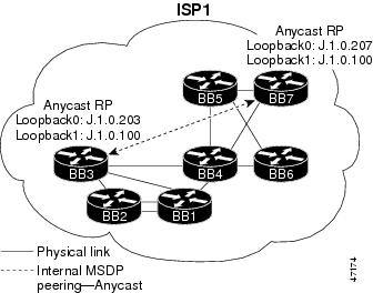
ISP1 is a larger, more established ISP that wants the flexibility to decide which of its IP addresses to advertise to other ISPs. ISP1 also wants redundancy and load-sharing capability within its multicast network. Therefore, ISP1 implemented two Anycast RPs at the edge of its network.
Anycast RP is a useful application of MSDP. This technique is used for configuring a multicast sparse mode network to provide for fault tolerance and load sharing within a single multicast domain.
Two or more RPs are configured with the same IP address (for example, 10.0.0.1) on loopback interfaces. The loopback address should be configured with a 32-bit mask. All the downstream routers are configured so that they know that 10.0.0.1 is the IP address of their local RP. IP routing automatically selects the topologically closest RP for each source and receiver. Because some sources use only one RP and some receivers a different RP, a method is needed for the RPs to exchange information about active sources. This information exchange is done with MSDP. All the RPs are configured to be MSDP peers of each other. Each RP will know about the active sources in the area of the other RP. If any of the RPs were to fail, IP routing would converge and one of the RPs would become the active RP in both areas.
Note ![]() The Anycast RP example in the previous paragraph used IP addresses from RFC 1918. These IP addresses are normally blocked at interdomain borders and therefore are not accessible to other ISPs. You must use valid IP addresses if you want the RPs to be reachable from other domains.
The Anycast RP example in the previous paragraph used IP addresses from RFC 1918. These IP addresses are normally blocked at interdomain borders and therefore are not accessible to other ISPs. You must use valid IP addresses if you want the RPs to be reachable from other domains.
Note ![]() There are several ways to configure a network to ensure that RPF checks will always succeed. These alternatives will not be discussed in this document.
There are several ways to configure a network to ensure that RPF checks will always succeed. These alternatives will not be discussed in this document.
ISP1—Intradomain Multicast Network Topology
Figure 6 shows the intradomain multicast network diagram for ISP1.
Figure 6 Network Diagram for ISP1—Intradomain Multicast
ISP1—Intradomain Multicast Benefits
The benefits of deploying the ISP1 multicast network are as follows:
•![]() Redundancy capability due to Anycast RPs. If one RP were to fail, the other RP would take over at the convergence rate of the unicast routing protocol.
Redundancy capability due to Anycast RPs. If one RP were to fail, the other RP would take over at the convergence rate of the unicast routing protocol.
•![]() Load-sharing capability due to Anycast RPs. Devices will use the RP they are topologically closest to (based on routing metric) in the network.
Load-sharing capability due to Anycast RPs. Devices will use the RP they are topologically closest to (based on routing metric) in the network.
•![]() Anycast RP mechanism depends only on the fast convergence of unicast routing.
Anycast RP mechanism depends only on the fast convergence of unicast routing.
ISP1—Intradomain Multicast Ramifications
The ramification of deploying the ISP1 multicast network is that it is more difficult to implement and troubleshoot than the network topology used for ISP2.
ISP1—Intradomain Multicast Configuration Summary
The following is a summary of the tasks that were performed to configure the devices in ISP1 for intradomain multicast:
Step 1 ![]() Configure multicast globally.
Configure multicast globally.
The following sample configuration, taken from the configuration file for the ISP1BB4 router, shows how to configure multicast globally on a router. Multicast is configured on all ISP1 routers.
ip multicast-routing distributed
Step 2 ![]() Configure multicast on the interfaces.
Configure multicast on the interfaces.
The following sample configuration shows how to configure multicast on an interface of the ISP1BB4 router. Multicast is configured on the interfaces of all the ISP1 routers.
interface POS1/0/0
ip pim sparse-mode
ip mroute-cache distributed
Step 3 ![]() Select the router to be RP.
Select the router to be RP.
To benefit from load sharing and redundancy, ISP1 implemented Anycast RPs in its network. The Anycast RPs of ISP1 (ISP1BB3 and ISP1BB7) are placed at the edge of the ISP domain. The following sample configuration shows how a unique IP address with a 32-bit mask is configured on the loopback interfaces of the Anycast RPs. The same unique loopback address is configured on both the ISP1BB3 and ISP1BB7 routers.
interface Loopback1
ip address J.1.0.100 255.255.255.255
ip pim sparse-mode
The following sample configuration shows how to configure an MSDP peering session between the ISP1BB3 and ISP1BB7 routers using the unique IP addresses that were already configured for BGP on the Loopback0 interface:
For the ISP1BB3 router:
ip msdp peer J.1.0.207 connect-source Loopback0
ip msdp cache-sa-state
ip msdp originator-id Loopback0
For the ISP1BB7 router:
ip msdp peer J.1.0.203 connect-source Loopback0
ip msdp cache-sa-state
ip msdp originator-id Loopback0
Note ![]() The configuration shown is applicable for intradomain multicast traffic, but creates a problem if ISP1 is connected to other ISPs. This problem and proposed solution is discussed further in the "ISP1—Implementing Interdomain Multicast" section later in this document.
The configuration shown is applicable for intradomain multicast traffic, but creates a problem if ISP1 is connected to other ISPs. This problem and proposed solution is discussed further in the "ISP1—Implementing Interdomain Multicast" section later in this document.
Step 4 ![]() Configure the RP statically on each router in ISP1.
Configure the RP statically on each router in ISP1.
The following sample configuration shows how to configure the RP address on each router in ISP1:
ip pim rp-address J.1.0.100
Step 5 ![]() Restrict available multicast groups from using 232/24. (Optional)
Restrict available multicast groups from using 232/24. (Optional)
Source Specific Multicast (SSM) will use the 232.0.0.0 through 232.255.255.255 address range for specific well-known sources. This address range will not require the use of an RP. The following sample configuration shows how to restrict the RP from allowing sources to register sources in this range. These statements need to be configured only on the RP.
ip pim accept-register list no-ssm-range
ip access-list extended no-ssm-range
deny ip any 232.0.0.0 0.255.255.255
permit ip any any
For the device characteristics and complete configuration files of the devices in ISP1, see the "ISP1—Device Characteristics and Complete Configuration Files" section of this document.
ISP1—Implementing Interdomain Multicast
This section contains the following subsections:
•![]() ISP1—Interdomain Multicast Network Topology
ISP1—Interdomain Multicast Network Topology
•![]() ISP1—Interdomain Multicast Configuration Summary
ISP1—Interdomain Multicast Configuration Summary
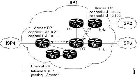
ISP1—Interdomain Multicast Network Topology
Figure 7 shows the interdomain multicast network diagram for ISP1.
Figure 7 Network Diagram for ISP1—Interdomain Multicast
ISP1—Interdomain Multicast Configuration Summary
The following is a summary of the tasks that were performed to configure the devices in ISP1 for interdomain multicast:
Step 1 ![]() Configure MBGP to exchange multicast routing information.
Configure MBGP to exchange multicast routing information.
a. ![]() Configure MBGP peering sessions.
Configure MBGP peering sessions.
The following MBGP peering sessions exist in ISP1:
–![]() ISP1BB3 externally peers with ISP4BB4.
ISP1BB3 externally peers with ISP4BB4.
–![]() ISP1BB6 externally peers with ISP3BB6.
ISP1BB6 externally peers with ISP3BB6.
–![]() ISP1BB7 externally peers with ISP2BB7.
ISP1BB7 externally peers with ISP2BB7.
–![]() All backbone routers in ISP1 internally peer with each other directly or through route reflectors.
All backbone routers in ISP1 internally peer with each other directly or through route reflectors.
The routers in ISP1 are running Cisco IOS Release 12.1 or 12.1 T software. These routers must be configured for multicast NLRI information using the address-family address family configuration command. The ISP1INTERNAL peer group is configured on every router in ISP1. The following sample configuration, taken from the configuration file for the ISP1BB3 router, shows how to configure the internal peers. The configuration is slightly different on the ISP1BB6 and ISP1BB7 routers.
router bgp 1
neighbor ISP1INTERNAL peer-group
neighbor ISP1INTERNAL remote-as 1
neighbor ISP1INTERNAL update-source Loopback0
!
address-family ipv4 multicast
neighbor ISP1INTERNAL activate
neighbor J.1.0.200 activate
neighbor J.1.0.201 activate
neighbor J.1.0.202 activate
neighbor J.1.0.204 activate
neighbor J.1.0.205 activate
neighbor J.1.0.208 activate
neighbor J.1.0.209 activate
neighbor J.1.0.210 activate
exit-address-family
The following sample configurations show how to configure the external peers. The configuration is different for each router.
For the ISP1BB3 router:
router bgp 1
neighbor ISP4ISP1PEER peer-group
neighbor ISP4ISP1PEER remote-as 4
neighbor J.4.0.33 peer-group ISP4ISP1PEER
!
address-family ipv4 multicast
neighbor ISP4ISP1PEER activate
neighbor J.4.0.33 activate
exit-address-family
For the ISP1BB6 router:
router bgp 1
neighbor ISP3ISP1PEER peer-group
neighbor ISP3ISP1PEER remote-as 3
neighbor J.3.0.245 peer-group ISP3ISP1PEER
!
address-family ipv4 multicast
neighbor J.3.0.245 activate
exit-address-family
For the ISP1BB7 router:
router bgp 1
neighbor J.2.0.253 remote-as 2
!
address-family ipv4 multicast
neighbor J.2.0.253 activate
exit-address-family
b. ![]() Verify that MBGP is configured properly.
Verify that MBGP is configured properly.
The following sample output shows how to verify that MBGP peers have negotiated for multicast routes:
ISP1BB3# show ip bgp neighbors J.4.0.33
BGP neighbor is J.4.0.33, remote AS 4, external link
Member of peer-group ISP4ISP1PEER for session parameters
BGP version 4, remote router ID J.4.0.204
BGP state = Established, up for 1d01h
Last read 00:00:19, hold time is 180, keepalive interval is 60 seconds
Neighbor capabilities:
Route refresh:advertised and received(new)
Address family IPv4 Unicast:advertised and received
Address family IPv4 Multicast:advertised
Received 1527053 messages, 1 notifications, 0 in queue
Sent 1525164 messages, 0 notifications, 0 in queue
Route refresh request:received 0, sent 0
Default minimum time between advertisement runs is 30 seconds
For address family:IPv4 Unicast
BGP table version 7180619, neighbor version 7180618
Index 2, Offset 0, Mask 0x4
ISP4ISP1PEER peer-group member
393 accepted prefixes consume 14148 bytes
Prefix advertised 3913222, suppressed 15560, withdrawn 569094
For address family:IPv4 Multicast
BGP table version 179740, neighbor version 0
Index 9, Offset 1, Mask 0x2
0 accepted prefixes consume 0 bytes
Prefix advertised 0, suppressed 0, withdrawn 0
Connections established 5; dropped 4
Last reset 6d02h, due to Peer closed the session
Connection state is ESTAB, I/O status:1, unread input bytes:0
Local host:J.4.0.34, Local port:179
Foreign host:J.4.0.33, Foreign port:11001
Enqueued packets for retransmit:0, input:0 mis-ordered:0 (0 bytes)
Event Timers (current time is 0xC44ED904):
Timer Starts Wakeups Next
Retrans 4226 20 0x0
TimeWait 0 0 0x0
AckHold 2577 2106 0x0
SendWnd 0 0 0x0
KeepAlive 0 0 0x0
GiveUp 0 0 0x0
PmtuAger 0 0 0x0
DeadWait 0 0 0x0
iss: 788905143 snduna: 789055186 sndnxt: 789055186 sndwnd: 13161
irs: 788903705 rcvnxt: 788982188 rcvwnd: 15115 delrcvwnd: 1269
SRTT:300 ms, RTTO:303 ms, RTV:3 ms, KRTT:0 ms
minRTT:0 ms, maxRTT:304 ms, ACK hold:200 ms
Flags:passive open, nagle, gen tcbs
Datagrams (max data segment is 4430 bytes):
Rcvd:5847 (out of order:0), with data:2577, total data bytes:78482
Sent:6330 (retransmit:20), with data:4205, total data bytes:150042
ISP1BB3#
ISP1BB3# show ip bgp ipv4 multicast summary
BGP router identifier J.1.0.203, local AS number 1
BGP table version is 179746, main routing table version 1
3 network entries and 1 paths using 330 bytes of memory
8 BGP path attribute entries using 480 bytes of memory
2 BGP rrinfo entries using 48 bytes of memory
3 BGP AS-PATH entries using 72 bytes of memory
0 BGP route-map cache entries using 0 bytes of memory
0 BGP filter-list cache entries using 0 bytes of memory
BGP activity 399426/517203 prefixes, 3845743/3844578 paths, scan interval 15 secs
Neighbor V AS MsgRcvd MsgSent TblVer InQ OutQ Up/Down State/PfxRcd
J.1.0.200 4 1 69546 1027381 179746 0 0 5w3d 0
J.1.0.201 4 1 54860 1027256 179746 0 0 2w6d 0
J.1.0.202 4 1 54846 1027272 179746 0 0 2w6d 0
J.1.0.204 4 1 1822972 1027387 179746 0 0 5w3d 0
J.1.0.205 4 1 996842 1027387 179746 0 0 5w3d 1
J.1.0.208 4 1 70235 1027387 179746 0 0 5w3d 0
J.1.0.209 4 1 76084 1027381 179746 0 0 5w3d 0
J.1.0.210 4 1 67412 1027068 179746 0 0 5w2d 0
J.4.0.33 4 4 1527057 1525173 0 0 0 1d01h 0
ISP1BB3#
Step 2 ![]() Configure MSDP peering sessions.
Configure MSDP peering sessions.
The configuration of the BGP route reflector servers and route reflector clients adds some complexity to the configuration of ISP1. For example, the MSDP peers must perform an RPF check to verify from which AS the SA messages originated, and the IP addresses must match the IP address of the route reflector server. To ensure that RPF checks will always succeed in the ISP1 network, the route reflector server (ISP1BB4) is configured to have an MSDP peering sessions with the Anycast RPs (ISP1BB3 and ISP1BB7). In addition, the direct peering relationship between ISP1BB3 and ISP1BB7 is removed.
a. ![]() Select an IP address.
Select an IP address.
For MSDP peering sessions, we use the same IP address that was used for the BGP peering session. In this case, it is the unique IP address with a 32-bit mask configured on Loopback0.
b. ![]() Configure peering sessions.
Configure peering sessions.
As shown in Figure 7, the following new intradomain Anycast peering sessions exist in ISP1:
–![]() ISP1BB3 peers with ISP1BB4
ISP1BB3 peers with ISP1BB4
–![]() ISP1BB4 peers with ISP1BB7
ISP1BB4 peers with ISP1BB7
As shown in Figure 3, the following MSDP peering sessions exist in ISP1:
–![]() ISP1BB3 peers with ISP4BB3
ISP1BB3 peers with ISP4BB3
–![]() ISP1BB7 peers with ISP2BB4
ISP1BB7 peers with ISP2BB4
The following sample configurations show how to configure the MSDP peering sessions in ISP1:
For the ISP1BB3 router:
ip msdp peer J.4.0.203 connect-source Loopback0 remote-as 4
ip msdp peer J.1.0.204 connect-source Loopback0
ip msdp originator-id Loopback0
For the ISP1BB4 router:
ip msdp peer J.1.0.203 connect-source Loopback0
ip msdp peer J.1.0.207 connect-source Loopback0
For the ISP1BB7 router:
ip msdp peer J.2.0.204 connect-source Loopback0 remote-as 2
ip msdp peer J.1.0.204 connect-source Loopback0
ip msdp originator-id Loopback0
Step 3 ![]() Configure recommended SA filters.
Configure recommended SA filters.
The following sample configurations show how to configure the SA filters on the RPs of ISP1 (ISP1BB3 and ISP1BB7):
For the ISP1BB3 router (connection to the ISP4BB3 router):
ip msdp sa-filter in J.4.0.203 list 124
ip msdp sa-filter out J.4.0.203 list 124
For the ISP1BB7 router (connection to the ISP2BB4 router):
ip msdp sa-filter in J.2.0.204 list 124
ip msdp sa-filter out J.2.0.204 list 124
The following access list is configured on both the ISP1BB3 and ISP1BB7 routers:
access-list 124 deny ip any host 224.0.2.2
access-list 124 deny ip any host 224.0.1.3
access-list 124 deny ip any host 224.0.1.24
access-list 124 deny ip any host 224.0.1.22
access-list 124 deny ip any host 224.0.1.2
access-list 124 deny ip any host 224.0.1.35
access-list 124 deny ip any host 224.0.1.60
access-list 124 deny ip any host 224.0.1.39
access-list 124 deny ip any host 224.0.1.40
access-list 124 deny ip any 239.0.0.0 0.255.255.255
access-list 124 deny ip 10.0.0.0 0.255.255.255 any
access-list 124 deny ip 127.0.0.0 0.255.255.255 any
access-list 124 deny ip 172.16.0.0 0.15.255.255 any
access-list 124 deny ip 192.168.0.0 0.0.255.255 any
access-list 124 deny ip any 232.0.0.0 0.255.255.255
Step 4 ![]() Configure SA caching.
Configure SA caching.
The following sample configuration shows how to enable SA caching. This feature is enabled on all the routers in ISP1 running MSDP (ISP1BB3, ISP1BB4, and ISP1BB7 routers).
ip msdp cache-sa-state
Step 5 ![]() Verify that MSDP peers are working properly.
Verify that MSDP peers are working properly.
The following sample output shows how to verify that MSDP peers are working properly:
ISP1BB3# show ip msdp peer J.4.0.203
MSDP Peer J.4.0.203 (?), AS 4 (configured AS)
Description:
Connection status:
State:Up, Resets:4, Connection source:Loopback0 (J.1.0.203)
Uptime(Downtime):1d06h, Messages sent/received:4022/5221
Output messages discarded:0
Connection and counters cleared 5w3d ago
SA Filtering:
Input (S,G) filter:124, route-map:none
Input RP filter:none, route-map:none
Output (S,G) filter:124, route-map:none
Output RP filter:none, route-map:none
SA-Requests:
Input filter:none
Sending SA-Requests to peer:enabled
Peer ttl threshold:0
Input queue size:0, Output queue size:0
ISP1BB3#
Step 6 ![]() Configure multicast borders appropriately.
Configure multicast borders appropriately.
Multicast borders must be configured on every router interface that borders another ISP. For ISP1, multicast borders are configured on the ISP1BB3, ISP1BB6, and ISP1BB7 routers. The following sample configuration, taken from the configuration file for the ISP1BB3 router, shows how to configure multicast borders:
interface POS9/0/0
description TO ISP4BB4, POS 12/0/0
ip pim bsr-border
ip pim sparse-mode
ip multicast boundary 10
!
access-list 10 deny 224.0.1.39
access-list 10 deny 224.0.1.40
access-list 10 deny 239.0.0.0 0.255.255.255
access-list 10 permit any
For the device characteristics and complete configuration files of the devices in ISP1, see the "ISP1—Device Characteristics and Complete Configuration Files" section of this document.
ISP1—Connecting Customers into Infrastructure
This section contains the following subsections:
•![]() Internal RP Scenario Without MBGP
Internal RP Scenario Without MBGP
External RP Scenario
This section contains the following subsections:
•![]() External RP—Configuration Summary
External RP—Configuration Summary
External RP—Strategy
In this scenario, the customer uses the RP in ISP1 for multicasting. This customer requires its internal content to be seen by others outside the company.
External RP—Network Topology
The network topology for ISP1-POP is the same topology as ISP1 with the addition of a point of presence (POP). In Figure 8, ISP1AC2 represents the "external RP customer" scenario.
Figure 8 Network Diagram for ISP1-POP
External RP—Benefits
The benefits for customers using the RP of ISP1 for multicasting are as follows:
•![]() Allows controlled access to multicast content on the Internet.
Allows controlled access to multicast content on the Internet.
•![]() Configuration is simple.
Configuration is simple.
•![]() Requires minimal configuration.
Requires minimal configuration.
External RP—Ramifications
The ramification for customers using an external RP scenario for multicasting is the possibility for a denial of service attack by another customer of the ISP.
External RP—Configuration Summary
The following is a summary of the tasks that were performed to configure the ISP1AC2 router for multicasting using an RP in ISP1:
Step 1 ![]() Configure multicast globally.
Configure multicast globally.
ip multicast-routing
Step 2 ![]() Configure multicast on the interfaces.
Configure multicast on the interfaces.
interface fa3/0
ip pim sparse-mode
interface eth5/2
ip pim sparse-mode
Step 3 ![]() Configure the RP statically.
Configure the RP statically.
ip pim rp-address J.1.0.100
For the device characteristics and complete configuration files of the devices in ISP1-POP, see the "ISP1—Device Characteristics and Complete Configuration Files" section of this document.
Internal RP Scenario Without MBGP
This section contains the following subsections:
•![]() Internal RP—Intradomain Multicast Configuration Summary
Internal RP—Intradomain Multicast Configuration Summary
•![]() Internal RP—Interdomain Multicast Configuration Summary
Internal RP—Interdomain Multicast Configuration Summary
Internal RP—Strategy
In this scenario, the customer uses its own internal RP for multicasting without MBGP. This customer wants the flexibility to decide whether its internal multicast content can be seen by others outside of the company. The internal RP allows the customer to filter private multicast traffic.
Internal RP—Network Topology
See Figure 8. ISP1AC1 represents the "internal RP customer without MBGP" scenario. The customer is in the same AS as the provider.
Internal RP—Benefits
The benefits for customers using their own internal RP for multicasting without MBGP are as follows:
•![]() Allows access to multicast content on the Internet.
Allows access to multicast content on the Internet.
•![]() Customer can have its own multicast sessions that do not leave the company.
Customer can have its own multicast sessions that do not leave the company.
•![]() Customer can limit exposure to multicast denial of service attacks.
Customer can limit exposure to multicast denial of service attacks.
Internal RP—Ramifications
The ramification for customers using their own internal RP for multicasting without MBGP is that this scenario is more difficult to implement than the external RP scenario.
Internal RP—Intradomain Multicast Configuration Summary
The following is a summary of the tasks that were performed to configure the ISP1AC1 router for intradomain multicasting. In this example, the customer has only one router. If the customer has multiple routers, the intradomain multicast tasks should be performed on all of these routers.
Step 1 ![]() Configure multicast globally.
Configure multicast globally.
ip multicast-routing
Step 2 ![]() Configure multicast on the interfaces.
Configure multicast on the interfaces.
interface FastEthernet3/0
ip pim sparse-mode
interface Ethernet5/2
ip pim sparse-mode
interface Ethernet5/3
ip pim sparse-mode
Step 3 ![]() Select the router to be RP.
Select the router to be RP.
In this example, the customer has only one router (ISP1AC1). The following sample configuration shows how a unique IP address with a 32-bit mask is configured on the loopback interface of the RP (ISP1AC1).
interface Loopback0
ip address K.250.0.201 255.255.255.255
ip pim sparse-mode
ip mroute-cache distributed
no shut
Step 4 ![]() Configure the RP statically.
Configure the RP statically.
ip pim rp-address K.250.0.201
Internal RP—Interdomain Multicast Configuration Summary
The following is a summary of the tasks that were performed to configure the ISP1AC1 router for interdomain multicasting. In this example, the customer has only one router. If the customer has multiple routers, the interdomain multicast tasks should be performed on all of these routers.
Step 1 ![]() Configure MSDP peering session.
Configure MSDP peering session.
The following sample configuration shows how to configure the peering session between the ISP1AC1 router and the ISP1BB3 router:
For the ISP1AC1 router:
ip msdp peer J.1.0.203 connect-source Loopback0
For the ISP1BB3 router:
ip msdp peer K.250.1.2 connect-source Loopback0
Step 2 ![]() Configure recommended SA filters.
Configure recommended SA filters.
The following sample configuration shows how to configure the SA filters on the ISP1AC1 router for the connection to the ISP1BB3 router:
ip msdp sa-filter in J.1.0.203 list 124
ip msdp sa-filter out J.1.0.203 list 124
access-list 124 deny ip any host 224.0.2.2
access-list 124 deny ip any host 224.0.1.3
access-list 124 deny ip any host 224.0.1.24
access-list 124 deny ip any host 224.0.1.22
access-list 124 deny ip any host 224.0.1.2
access-list 124 deny ip any host 224.0.1.35
access-list 124 deny ip any host 224.0.1.60
access-list 124 deny ip any host 224.0.1.39
access-list 124 deny ip any host 224.0.1.40
access-list 124 deny ip any 239.0.0.0 0.255.255.255
access-list 124 deny ip 10.0.0.0 0.255.255.255 any
access-list 124 deny ip 127.0.0.0 0.255.255.255 any
access-list 124 deny ip 172.16.0.0 0.15.255.255 any
access-list 124 deny ip K.168.0.0 0.0.255.255 any
access-list 124 deny ip any 232.0.0.0 0.255.255.255
access-list 124 permit ip any any
Step 3 ![]() Configure SA caching.
Configure SA caching.
The following sample configuration shows how to enable SA caching. This feature is enabled on the ISP1AC1 router.
ip msdp cache-sa-state
Step 4 ![]() Verify that MSDP peers are working properly.
Verify that MSDP peers are working properly.
The following sample output shows how to verify that MSDP peers are working properly:
ISP1AC1# show ip msdp peer
MSDP Peer J.1.0.203 (?), AS ?
Description:
Connection status:
State:Up, Resets:1, Connection source:Loopback0 (K.250.0.201)
Uptime(Downtime):2w1d, Messages sent/received:21824/66342
Output messages discarded:0
Connection and counters cleared 2w2d ago
SA Filtering:
Input (S,G) filter:124, route-map:none
Input RP filter:none, route-map:none
Output (S,G) filter:124, route-map:none
Output RP filter:none, route-map:none
SA-Requests:
Input filter:none
Sending SA-Requests to peer:disabled
Peer ttl threshold:0
Input queue size:0, Output queue size:0
Step 5 ![]() Configure multicast borders appropriately.
Configure multicast borders appropriately.
The following sample configuration shows how to configure a multicast border on the ISP1AC1 router:
interface FastEthernet3/0
ip pim bsr-border
ip pim sparse-mode
ip multicast boundary 1
access-list 1 deny 224.0.1.39
access-list 1 deny 224.0.1.40
access-list 1 deny 239.0.0.0 0.255.255.255
access-list 1 permit any
For the device characteristics and complete configuration files of the devices in ISP1-POP, see the "ISP1—Device Characteristics and Complete Configuration Files" section of this document.
ISP3 and ISP4 Scenarios
This section contains the "ISP3 and ISP4—Implementing Interdomain Multicast" subsection.
ISP3 and ISP4—Implementing Interdomain Multicast
The detailed network scenarios of ISP3 and ISP4 will not be discussed in this document. For these two ISPs, we will focus only on the routers that are configured to implement interdomain multicast among the ISP1, ISP2, ISP3, and ISP4 domains.
This section contains the following subsections:
•![]() ISP3—Interdomain Multicast Network Topology
ISP3—Interdomain Multicast Network Topology
•![]() ISP3—Interdomain Multicast Configuration Summary
ISP3—Interdomain Multicast Configuration Summary
•![]() ISP4—Interdomain Multicast Network Topology
ISP4—Interdomain Multicast Network Topology
•![]() ISP4—Interdomain Multicast Configuration Summary
ISP4—Interdomain Multicast Configuration Summary
ISP3—Interdomain Multicast Network Topology
Figure 9 shows the interdomain multicast network diagram for ISP3.
Figure 9 Network Diagram for ISP3—Interdomain Multicast
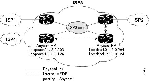
ISP3—Interdomain Multicast Configuration Summary
The following is a summary of the tasks that were performed to configure the devices in ISP3 for interdomain multicast:
Step 1 ![]() Configure MBGP to exchange multicast routing information.
Configure MBGP to exchange multicast routing information.
a. ![]() Configure MBGP peering sessions.
Configure MBGP peering sessions.
The following MBGP peering sessions exist in ISP3:
–![]() ISP3BB3 externally peers with ISP4BB3.
ISP3BB3 externally peers with ISP4BB3.
–![]() ISP3BB6 externally peers with ISP1BB6.
ISP3BB6 externally peers with ISP1BB6.
–![]() ISP3BB7 externally peers with ISP2BB3.
ISP3BB7 externally peers with ISP2BB3.
–![]() All backbone routers in ISP3 internally peer with each other directly or through route reflectors.
All backbone routers in ISP3 internally peer with each other directly or through route reflectors.
The routers in ISP3 are running Cisco IOS Release 12.1 or 12.1 T software. These routers must be configured for multicast NLRI information using the address-family address family configuration command. The ISP3INTERNAL peer group is configured on every router in ISP3. The following sample configuration, taken from the configuration file for the ISP3BB3 router, shows how to configure the internal peers. The configuration is slightly different on the ISP3BB6 and ISP3BB7 routers.
router bgp 3
neighbor ISP3INTERNAL peer-group
neighbor ISP3INTERNAL remote-as 3
neighbor ISP3INTERNAL update-source Loopback0
neighbor J.3.0.201 peer-group ISP3INTERNAL
neighbor J.3.0.202 peer-group ISP3INTERNAL
neighbor J.3.0.204 peer-group ISP3INTERNAL
neighbor J.3.0.205 peer-group ISP3INTERNAL
neighbor J.3.0.206 peer-group ISP3INTERNAL
neighbor J.3.0.207 peer-group ISP3INTERNAL
neighbor J.3.0.240 remote-as 3
neighbor J.3.0.240 update-source Loopback0
!
address-family ipv4 multicast
neighbor ISP3INTERNAL activate
neighbor ISP3ISP4PEER activate
neighbor J.3.0.201 activate
neighbor J.3.0.202 activate
neighbor J.3.0.204 activate
neighbor J.3.0.205 activate
neighbor J.3.0.206 activate
neighbor J.3.0.207 activate
neighbor J.3.0.240 activate
exit-address-family
!
The following sample configurations show how to configure the external peers. The configuration is different for each router.
For the ISP3BB3 router:
router bgp 3
neighbor ISP3ISP4PEER peer-group
neighbor J.3.0.250 remote-as 4
neighbor J.3.0.250 peer-group ISP3ISP4PEER
!
address-family ipv4 multicast
neighbor ISP3ISP4PEER activate
neighbor J.3.0.250 activate
exit-address-family
For the ISP3BB6 router:
router bgp 3
neighbor ISP3ISP1PEER peer-group
neighbor ISP3ISP1PEER remote-as 1
neighbor J.3.0.246 peer-group ISP3ISP1PEER
!
address-family ipv4 multicast
neighbor ISP3ISP1PEER activate
neighbor J.3.0.246 activate
exit-address-family
For the ISP3BB7 router:
router bgp 3
neighbor ISP3ISP2PEER peer-group
neighbor ISP3ISP2PEER remote-as 2
neighbor J.2.0.245 peer-group ISP3ISP2PEER
!
address-family ipv4 multicast
neighbor ISP3ISP2PEER activate
neighbor J.2.0.245 activate
exit-address-family
b. ![]() Verify that MBGP is configured properly.
Verify that MBGP is configured properly.
The following sample output shows how to verify that MBGP peers have negotiated for multicast routes:
ISP3BB6# show ip bgp neighbors J.3.0.246
BGP neighbor is J.3.0.246, remote AS 1, external link
Member of peer-group ISP3ISP1PEER for session parameters
BGP version 4, remote router ID J.1.0.206
BGP state = Established, up for 1w0d
Last read 00:00:49, hold time is 180, keepalive interval is 60 seconds
Neighbor capabilities:
Route refresh:advertised and received(new)
Address family IPv4 Unicast:advertised and received
Address family IPv4 Multicast:advertised and received
Received 18404 messages, 0 notifications, 0 in queue
Sent 18548 messages, 0 notifications, 0 in queue
Route refresh request:received 0, sent 0
Default minimum time between advertisement runs is 30 seconds
For address family:IPv4 Unicast
BGP table version 726089, neighbor version 726089
Index 1, Offset 0, Mask 0x2
ISP3ISP1PEER peer-group member
50376 accepted prefixes consume 1813536 bytes
Prefix advertised 388255, suppressed 26, withdrawn 337751
For address family:IPv4 Multicast
BGP table version 22917, neighbor version 22917
Index 8, Offset 1, Mask 0x1
0 accepted prefixes consume 0 bytes
Prefix advertised 265, suppressed 0, withdrawn 263
Connections established 1; dropped 0
Last reset never
Connection state is ESTAB, I/O status:1, unread input bytes:0
Local host:J.3.0.245, Local port:11019
Foreign host:J.3.0.246, Foreign port:179
Enqueued packets for retransmit:0, input:0 mis-ordered:0 (0 bytes)
Event Timers (current time is 0x287B19C4):
Timer Starts Wakeups Next
Retrans 14396 46 0x0
TimeWait 0 0 0x0
AckHold 14205 11580 0x0
SendWnd 0 0 0x0
KeepAlive 0 0 0x0
GiveUp 0 0 0x0
PmtuAger 0 0 0x0
DeadWait 0 0 0x0
iss:2895360363 snduna:2898650079 sndnxt:2898650079 sndwnd: 14007
irs:2895361023 rcvnxt:2898664417 rcvwnd: 14970 delrcvwnd: 1414
SRTT:300 ms, RTTO:303 ms, RTV:3 ms, KRTT:0 ms
minRTT:0 ms, maxRTT:484 ms, ACK hold:200 ms
Flags:higher precedence, nagle
Datagrams (max data segment is 4430 bytes):
Rcvd:29082 (out of order:0), with data:14786, total data bytes:3303393
Sent:27252 (retransmit:46), with data:14751, total data bytes:3289715
ISP3BB6# show ip bgp ipv4 multicast summary
BGP router identifier J.3.0.206, local AS number 3
BGP table version is 22917, main routing table version 1
6 network entries and 2 paths using 660 bytes of memory
292 BGP path attribute entries using 17520 bytes of memory
7 BGP rrinfo entries using 168 bytes of memory
99 BGP AS-PATH entries using 5832 bytes of memory
187 BGP extended community entries using 4488 bytes of memory
0 BGP route-map cache entries using 0 bytes of memory
0 BGP filter-list cache entries using 0 bytes of memory
BGP activity 388470/342418 prefixes, 401299/350266 paths, scan interval 15 secs
Neighbor V AS MsgRcvd MsgSent TblVer InQ OutQ Up/Down State/PfxRcd
J.3.0.201 4 3 11546 12644 22917 0 0 1w0d 0
J.3.0.202 4 3 11362 12644 22917 0 0 1w0d 0
J.3.0.203 4 3 11919 12644 22917 0 0 1w0d 1
J.3.0.204 4 3 11322 11905 22917 0 0 1w0d 0
J.3.0.205 4 3 11328 11905 22917 0 0 1w0d 1
J.3.0.207 4 3 11403 11905 22917 0 0 1w0d 0
J.3.0.241 4 3 12377 12620 0 0 0 2d16h 0
J.3.0.246 4 1 18405 18549 22917 0 0 1w0d 0
Step 2 ![]() Configure MSDP peering sessions.
Configure MSDP peering sessions.
The configuration of the BGP route reflector servers and route reflector clients adds some complexity to the configuration of ISP3. For example, the MSDP peers must perform an RPF check to verify from which AS the SA messages originated, and the IP addresses must match the IP address of the route reflector server. To ensure that RPF checks will always succeed in the ISP3 network, the router reflector server (ISP3BB4) is configured to have an MSDP peering session with the Anycast RPs (ISP3BB3 and ISP3BB4).
a. ![]() Select an IP address.
Select an IP address.
For MSDP peering sessions, we use the same IP address that was used for the BGP peering session. In this case, it is the unique IP address with a 32-bit mask configured on Loopback0.
b. ![]() Configure peering sessions.
Configure peering sessions.
The following sample configurations show how to configure the MSDP peering sessions in ISP3:
For the ISP3BB3 router:
ip msdp peer J.3.0.250 connect-source Loopback0 remote-as 4
ip msdp peer J.3.0.204 connect-source Loopback0 remote-as 3
For the ISP3BB4 router:
ip msdp peer J.3.0.203 connect-source Loopback0
ip msdp peer J.3.0.207 connect-source Loopback0
For the ISP3BB7 router:
ip msdp peer J.3.0.204 connect-source Loopback0
ip msdp peer J.2.0.204 connect-source Loopback0 remote-as 2
Step 3 ![]() Configure recommended SA filters.
Configure recommended SA filters.
The following sample configurations show how to configure the SA filters on the RPs of ISP3 (ISP3BB3 and ISP3BB4):
For the ISP3BB3 router (connection to the ISP4BB3 router):
ip msdp sa-filter in J.3.0.250 list 124
ip msdp sa-filter out J.3.0.250 list 124
For the ISP3BB7 router (connection to the ISP2BB3 router):
ip msdp sa-filter in J.2.0.204 list 124
ip msdp sa-filter out J.2.0.204 list 124
The following access list is configured on both the ISP3BB3 and ISP3BB7 routers:
access-list 124 deny ip any host 224.0.2.2
access-list 124 deny ip any host 224.0.1.3
access-list 124 deny ip any host 224.0.1.24
access-list 124 deny ip any host 224.0.1.22
access-list 124 deny ip any host 224.0.1.2
access-list 124 deny ip any host 224.0.1.35
access-list 124 deny ip any host 224.0.1.60
access-list 124 deny ip any host 224.0.1.39
access-list 124 deny ip any host 224.0.1.40
access-list 124 deny ip any 239.0.0.0 0.255.255.255
access-list 124 deny ip 10.0.0.0 0.255.255.255 any
access-list 124 deny ip 127.0.0.0 0.255.255.255 any
access-list 124 deny ip 172.16.0.0 0.15.255.255 any
access-list 124 deny ip K.168.0.0 0.0.255.255 any
access-list 124 permit ip any any
Step 4 ![]() Configuring SA caching.
Configuring SA caching.
The following sample configuration shows how to enable SA caching. This feature is enabled on all the routers in ISP3 running MSDP (ISP3BB3, ISP3BB4, and ISP3BB7 routers).
ip msdp cache-sa-state
Step 5 ![]() Verify that MSDP peers are working properly.
Verify that MSDP peers are working properly.
The following sample output shows how to verify that MSDP peers are working properly:
ISP3BB3# show ip msdp peer J.3.0.250
MSDP Peer J.3.0.250 (?), AS 4
Description:
Connection status:
State:Up, Resets:1, Connection source:none configured
Uptime(Downtime):10:05:21, Messages sent/received:605/3321
Output messages discarded:0
Connection and counters cleared 2w3d ago
SA Filtering:
Input (S,G) filter:124, route-map:none
Input RP filter:none, route-map:none
Output (S,G) filter:124, route-map:none
Output RP filter:none, route-map:none
SA-Requests:
Input filter:none
Sending SA-Requests to peer:enabled
Peer ttl threshold:0
Input queue size:0, Output queue size:0
Step 6 ![]() Configure multicast borders appropriately.
Configure multicast borders appropriately.
Multicast borders must be configured on every router interface that borders another ISP. For ISP3, multicast borders are configured on the ISP3BB3, ISP3BB6, and ISP3BB7 routers. The following sample configuration, taken from the configuration file for the ISP3BB3 router, shows how to configure multicast borders:
interface POS12/0/0
description Connected to ISP4BB3, POS12/0/0
ip pim bsr-border
ip pim sparse-mode
ip multicast boundary 1
!
access-list 1 deny 224.0.1.39
access-list 1 deny 224.0.1.40
access-list 1 deny 239.0.0.0 0.255.255.255
access-list 1 permit any
For the device characteristics and complete configuration files of the significant devices in ISP3, see the "ISP3 and ISP4—Device Characteristics and Complete Configuration Files" section of this document.
ISP4—Interdomain Multicast Network Topology
Figure 10 shows the interdomain multicast network diagram for ISP4.
Figure 10 Network Diagram for ISP4—Interdomain Multicast
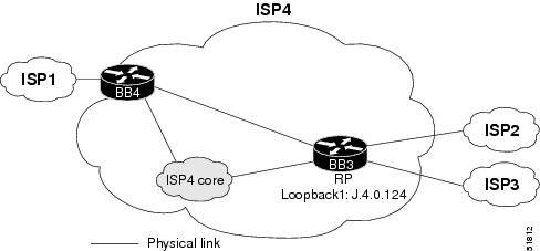
ISP4—Interdomain Multicast Configuration Summary
The following is a summary of the tasks that were performed to configure the devices in ISP4 for interdomain multicast:
Step 1 ![]() Configure MBGP to exchange multicast routing information.
Configure MBGP to exchange multicast routing information.
a. ![]() Configure MBGP peering sessions.
Configure MBGP peering sessions.
The following MBGP peering sessions exist in ISP4:
–![]() ISP4BB3 externally peers with ISP3BB3.
ISP4BB3 externally peers with ISP3BB3.
–![]() ISP4BB3 externally peers with ISP2BB6.
ISP4BB3 externally peers with ISP2BB6.
–![]() ISP4BB4 externally peers with ISP1BB3.
ISP4BB4 externally peers with ISP1BB3.
–![]() All backbone routers in ISP4 internally peer with each other directly or through router reflectors.
All backbone routers in ISP4 internally peer with each other directly or through router reflectors.
The following sample configurations show how to configure the external peers. The configuration is different for each router.
For the ISP4BB3 router:
router bgp 4
neighbor ISP3ISP4PEER peer-group nlri unicast multicast
neighbor ISP4ISP2PEER peer-group nlri unicast multicast
neighbor ISP4INTERNAL peer-group nlri unicast multicast
For the ISP4BB4 router:
router bgp 4
neighbor ISP4INTERNAL peer-group nlri unicast multicast
neighbor ISP4ISP1PEER peer-group nlri unicast multicast
b. ![]() Verify that MBGP is configured properly.
Verify that MBGP is configured properly.
The following sample output shows how to verify that the MBGP peers have negotiated for multicast routes:
ISP4BB3# show ip bgp neighbors J.3.0.249
BGP neighbor is J.3.0.249, remote AS 3, external link
Member of peer-group ISP3ISP4PEER for session parameters
BGP version 4, remote router ID J.3.0.203
BGP state = Established, up for 00:08:45
Last read 00:00:46, hold time is 180, keepalive interval is 60 seconds
Neighbor capabilities:
Route refresh:advertised and received(new)
Address family IPv4 Unicast:advertised and received
Address family IPv4 Multicast:advertised and received
Received 5414 messages, 0 notifications, 0 in queue
Sent 4790 messages, 0 notifications, 0 in queue
Route refresh request:received 0, sent 0
Default minimum time between advertisement runs is 30 seconds
For address family:IPv4 Unicast
BGP table version 243679, neighbor version 243679
Index 1, Offset 0, Mask 0x2
ISP3ISP4PEER peer-group member
102 accepted prefixes consume 3672 bytes
Prefix advertised 241691, suppressed 2, withdrawn 89926
For address family:IPv4 Multicast
BGP table version 7, neighbor version 7
Index 2, Offset 0, Mask 0x4
2 accepted prefixes consume 72 bytes
Prefix advertised 1, suppressed 0, withdrawn 1
Connections established 4; dropped 3
Last reset 00:09:26, due to Address family activated
Connection state is ESTAB, I/O status:1, unread input bytes:0
Local host:J.3.0.250, Local port:179
Foreign host:J.3.0.249, Foreign port:11031
Enqueued packets for retransmit:0, input:0 mis-ordered:0 (0 bytes)
Event Timers (current time is 0x606BEC4):
Timer Starts Wakeups Next
Retrans 44 0 0x0
TimeWait 0 0 0x0
AckHold 33 11 0x0
SendWnd 6 0 0x0
KeepAlive 0 0 0x0
GiveUp 0 0 0x0
PmtuAger 0 0 0x0
DeadWait 0 0 0x0
iss:2625748112 snduna:2625894217 sndnxt:2625894217 sndwnd: 14092
irs:2625727436 rcvnxt:2625873688 rcvwnd: 12635 delrcvwnd: 3749
SRTT:309 ms, RTTO:376 ms, RTV:67 ms, KRTT:0 ms
minRTT:4 ms, maxRTT:552 ms, ACK hold:200 ms
Flags:passive open, nagle, gen tcbs
Datagrams (max data segment is 4430 bytes):
Rcvd:125 (out of order:0), with data:54, total data bytes:146251
Sent:115 (retransmit:6), with data:73, total data bytes:146098
ISP4BB3# show ip mbgp summary
BGP router identifier J.4.0.203, local AS number 4
BGP table version is 7, main routing table version 1
3 network entries and 3 paths using 399 bytes of memory
41 BGP path attribute entries using 2460 bytes of memory
37 BGP AS-PATH entries using 2076 bytes of memory
0 BGP route-map cache entries using 0 bytes of memory
0 BGP filter-list cache entries using 0 bytes of memory
BGP activity 120888/92256 prefixes, 213008/181966 paths, scan interval 15 secs
Neighbor V AS MsgRcvd MsgSent TblVer InQ OutQ Up/Down State/PfxRcd
J.2.0.249 4 2 4049 3878 7 0 0 00:09:19 1
J.3.0.249 4 3 5415 4791 7 0 0 00:09:13 2
J.4.0.201 4 4 1699 1697 0 0 0 00:09:22 0
J.4.0.202 4 4 1691 1697 0 0 0 00:09:17 0
J.4.0.204 4 4 1680 1684 0 0 0 00:09:16 0
Step 2 ![]() Configure MSDP peering sessions.
Configure MSDP peering sessions.
a. ![]() Select an IP address.
Select an IP address.
For MSDP peering sessions, we use the same IP address that was used for the BGP peering session. In this case, it is the unique IP address with a 32-bit mask configured on Loopback0.
b. ![]() Configure peering sessions.
Configure peering sessions.
The ISP4BB3 router peers with the ISP1BB3, ISP2BB4, and ISP3BB3 routers. The following sample configuration shows how to configure these peering sessions:
ip msdp peer J.3.0.249 connect-source Loopback0 remote-as 3
ip msdp peer J.2.0.204 connect-source Loopback0 remote-as 2
ip msdp peer J.1.0.203 connect-source Loopback0 remote-as 1
Step 3 ![]() Configure recommended SA filters.
Configure recommended SA filters.
The following sample configurations show how to configure the SA filters on the RP of ISP4 (ISP4BB3) for the connections to the ISP1BB3, ISP2BB4, and ISP3BB3 routers:
For the connection to the ISP1BB3 router:
ip msdp sa-filter in J.1.0.203 list 124
ip msdp sa-filter out J.1.0.203 list 124
For the connection to the ISP2BB4 router:
ip msdp sa-filter in J.2.0.204 list 124
ip msdp sa-filter out J.2.0.204 list 124
For the connection to the ISP3BB3 router:
ip msdp sa-filter in J.3.0.249 list 124
ip msdp sa-filter out J.3.0.249 list 124
The following access list is configured on the ISP4BB3 router:
access-list 124 deny ip any host 224.0.2.2
access-list 124 deny ip any host 224.0.1.3
access-list 124 deny ip any host 224.0.1.24
access-list 124 deny ip any host 224.0.1.22
access-list 124 deny ip any host 224.0.1.2
access-list 124 deny ip any host 224.0.1.35
access-list 124 deny ip any host 224.0.1.60
access-list 124 deny ip any host 224.0.1.39
access-list 124 deny ip any host 224.0.1.40
access-list 124 deny ip any 239.0.0.0 0.255.255.255
access-list 124 deny ip 10.0.0.0 0.255.255.255 any
access-list 124 deny ip 127.0.0.0 0.255.255.255 any
access-list 124 deny ip 172.16.0.0 0.15.255.255 any
access-list 124 deny ip K.168.0.0 0.0.255.255 any
Step 4 ![]() Configure SA caching.
Configure SA caching.
The following sample configuration shows how to enable SA caching. This feature is enabled on the ISP4BB3 router.
ip msdp cache-sa-state
Step 5 ![]() Verify that MSDP peers are working properly.
Verify that MSDP peers are working properly.
The following sample output shows how to verify that the MSDP peers are working properly:
ISP4BB3# show ip msdp peer
MSDP Peer J.3.0.249 (?), AS 3
Description:
Connection status:
State:Up, Resets:1, Connection source:none configured
Uptime(Downtime):01:47:57, Messages sent/received:554/111
Output messages discarded:0
Connection and counters cleared 1d04h ago
SA Filtering:
Input (S,G) filter:124, route-map:none
Input RP filter:none, route-map:none
Output (S,G) filter:124, route-map:none
Output RP filter:none, route-map:none
SA-Requests:
Input filter:none
Sending SA-Requests to peer:enabled
Peer ttl threshold:0
Input queue size:0, Output queue size:0
MSDP Peer J.2.0.204 (?), AS 2 (configured AS)
Description:
Connection status:
State:Up, Resets:1, Connection source:Loopback0 (J.4.0.203)
Uptime(Downtime):00:49:19, Messages sent/received:163/108
Output messages discarded:0
Connection and counters cleared 1d04h ago
SA Filtering:
Input (S,G) filter:124, route-map:none
Input RP filter:none, route-map:none
Output (S,G) filter:124, route-map:none
Output RP filter:none, route-map:none
SA-Requests:
Input filter:none
Sending SA-Requests to peer:enabled
Peer ttl threshold:0
Input queue size:0, Output queue size:0
MSDP Peer J.1.0.203 (?), AS 1 (configured AS)
Description:
Connection status:
State:Up, Resets:1, Connection source:Loopback0 (J.4.0.203)
Uptime(Downtime):00:49:31, Messages sent/received:155/164
Output messages discarded:0
Connection and counters cleared 1d04h ago
SA Filtering:
Input (S,G) filter:124, route-map:none
Input RP filter:none, route-map:none
Output (S,G) filter:124, route-map:none
Output RP filter:none, route-map:none
SA-Requests:
Input filter:none
Sending SA-Requests to peer:enabled
Peer ttl threshold:0
Input queue size:0, Output queue size:0
Step 6 ![]() Configure multicast borders appropriately.
Configure multicast borders appropriately.
Multicast borders must be configured on every router interface that borders another ISP. For ISP4, multicast borders are configured on the ISP4BB3 and ISP4BB4 routers. The following sample configuration, taken from the configuration file for the ISP4BB3 router, shows how to configure multicast borders:
interface POS5/0/0
description TO ISP2BB6, POS 0/0
ip pim bsr-border
ip pim sparse-mode
ip multicast boundary 1
interface POS12/0/0
description To ISP3BB3, POS 12/0/0
ip pim bsr-border
ip pim sparse-mode
ip multicast boundary 1
access-list 1 deny 224.0.1.39
access-list 1 deny 224.0.1.40
access-list 1 deny 239.0.0.0 0.255.255.255
access-list 1 permit any
For the device characteristics and complete configuration files of the significant devices in ISP4, see the "ISP3 and ISP4—Device Characteristics and Complete Configuration Files" section of this document.
Related Documents
•![]() IP Multicast Technology Overview, Cisco white paper
IP Multicast Technology Overview, Cisco white paper
http://www.cisco.com/univercd/cc/td/doc/cisintwk/intsolns/mcst_sol/mcst_ovr.htm
•![]() MSDP Feature Broadens Reach of Multicast Services, Cisco Beyond Basic IP Newsletter V1.22
MSDP Feature Broadens Reach of Multicast Services, Cisco Beyond Basic IP Newsletter V1.22
http://www.cisco.com/warp/public/779/servpro/promotions/bbip/volume_01_issue22.html
•![]() PIM-SM Protocol Improves Multicast Service Availability, Cisco Beyond Basic IP Newsletter V1.11
PIM-SM Protocol Improves Multicast Service Availability, Cisco Beyond Basic IP Newsletter V1.11
http://www.cisco.com/warp/public/779/servpro/promotions/bbip/volume_01_issue11.html
•![]() Multicast Source Discovery Protocol, Cisco IOS Release 12.0(7)T feature module
Multicast Source Discovery Protocol, Cisco IOS Release 12.0(7)T feature module
http://www.cisco.com/univercd/cc/td/doc/product/software/ios120/120newft/120t/120t7/msdp.htm
•![]() Multiprotocol BGP Extensions for IP Multicast, Cisco IOS Release 12.0(7)T feature module
Multiprotocol BGP Extensions for IP Multicast, Cisco IOS Release 12.0(7)T feature module
http://www.cisco.com/univercd/cc/td/doc/product/software/ios120/120newft/120t/120t7/mbgp.htm
•![]() Changes in MBGP Commands Between 12.0S and 12.0T/12.1, Cisco Application Note
Changes in MBGP Commands Between 12.0S and 12.0T/12.1, Cisco Application Note
http://www.cisco.com/warp/public/cc/pd/iosw/prodlit/mcb12_an.htm
•![]() Multicast Source Discovery Protocol SA Filter Recommendations, Cisco Tech Note
Multicast Source Discovery Protocol SA Filter Recommendations, Cisco Tech Note
http://www.cisco.com/warp/public/105/49.html
•![]() Multicast Quick-Start Configuration Guide, Cisco Tech Note
Multicast Quick-Start Configuration Guide, Cisco Tech Note
http://www.cisco.com/warp/customer/105/48.html
•![]() Cisco IOS IP and IP Routing Configuration Guide, Release 12.1
Cisco IOS IP and IP Routing Configuration Guide, Release 12.1
http://www.cisco.com/univercd/cc/td/doc/product/software/ios121/121cgcr/ip_c/index.htm
•![]() Cisco IOS IP and IP Routing Command Reference, Release 12.1
Cisco IOS IP and IP Routing Command Reference, Release 12.1
http://www.cisco.com/univercd/cc/td/doc/product/software/ios121/121cgcr/ip_r/index.htm
•![]() Cisco IOS Software IP Multicast Group External Homepage
Cisco IOS Software IP Multicast Group External Homepage
ftp://ftpeng.cisco.com/ipmulticast/index.html
•![]() Cisco IOS Software Multicast Services Web Page
Cisco IOS Software Multicast Services Web Page
http://www.cisco.com/go/ipmulticast
•![]() RFC 1918, Address Allocation for Private Internets
RFC 1918, Address Allocation for Private Internets
•![]() RFC 2283, Multiprotocol Extensions for BGP-4
RFC 2283, Multiprotocol Extensions for BGP-4
•![]() RFC 2362, Protocol Independent Multicast-Sparse Mode (PIM-SM): Protocol Specification
RFC 2362, Protocol Independent Multicast-Sparse Mode (PIM-SM): Protocol Specification
 Feedback