- Pseudowire Emulation Edge-to-Edge MIBs for Ethernet, Frame Relay, and ATM Services
- MPLS EM�MPLS LSP Multipath Tree Trace
- MPLS Enhancements to Interfaces MIB
- MPLS Label Distribution Protocol MIB
- MPLS Label Distribution Protocol MIB Version 8 Upgrade
- MPLS LSP Ping/Traceroute for LDP/TE, and LSP Ping for VCCV
- MPLS Label Switching Router MIB
- Monitoring MPLS VPNs with MIBs
- MPLS Traffic Engineering - Fast Reroute MIB
- MPLS Traffic Engineering MIB
- MPLS VPN�MIB Support
- MPLS VPN�SNMP Notifications
- Contents
- Prerequisites for MPLS LDP MIB Version 8 Upgrade
- Restrictions for MPLS LDP MIB Version 8 Upgrade
- Information About MPLS LDP MIB Version 8 Upgrade
- Description of MPLS LDP MIB Elements for MPLS LDP MIB Version 8 Upgrade
- Events Generating MPLS LDP MIB Notifications in MPLS LDP MIB Version 8 Upgrade
- MIB Tables in MPLS LDP MIB Version 8 Upgrade
- mplsLdpEntityTable
- mplsLdpEntityConfGenLRTable
- mplsLdpEntityAtmParmsTable
- mplsLdpEntityConfAtmLRTable
- mplsLdpEntityStatsTable
- mplsLdpPeerTable
- mplsLdpHelloAdjacencyTable
- mplsLdpSessionTable
- mplsLdpAtmSesTable
- mplsLdpSesStatsTable
- VPN Contexts in MPLS LDP MIB Version 8 Upgrade
- SNMP Contexts
- VPN Aware LDP MIB Sessions
- VPN Aware LDP MIB Notifications
- How to Configure MPLS LDP MIB Version 8 Upgrade
- Configuration Examples for MPLS LDP MIB Version 8 Upgrade
- Additional References
- Command Reference
- Glossary
MPLS Label Distribution Protocol MIB Version 8 Upgrade
The MPLS Label Distribution Protocol (LDP) MIB Version 8 Upgrade feature enhances the LDP MIB to support the Internet Engineering Task Force (IETF) draft Version 8.

Note ![]() In Cisco IOS Release 12.2(33)SRB and Cisco IOS Release 12.2(33)SB, this MIB has been deprecated and replaced by MPLS-LDP-STD-MIB (RFC 3815). In those two releases and in later images, the entire MIB can be referenced by the name mplsLdpMIB for purposes of the SNMP server excluded/included command. If other MIB object names need to be referenced on the router, they must be referenced by MPLS-LDP-MIB::<table_entry_name>.
In Cisco IOS Release 12.2(33)SRB and Cisco IOS Release 12.2(33)SB, this MIB has been deprecated and replaced by MPLS-LDP-STD-MIB (RFC 3815). In those two releases and in later images, the entire MIB can be referenced by the name mplsLdpMIB for purposes of the SNMP server excluded/included command. If other MIB object names need to be referenced on the router, they must be referenced by MPLS-LDP-MIB::<table_entry_name>.
History for MLPS Label Distribution Protocol MIB Version 8 Update Feature
Finding Support Information for Platforms and Cisco IOS and Catalyst OS Software Images
Use Cisco Feature Navigator to find information about platform support and Cisco IOS and Catalyst OS software image support. To access Cisco Feature Navigator, go to http://www.cisco.com/go/cfn. An account on Cisco.com is not required.
Contents
•![]() Prerequisites for MPLS LDP MIB Version 8 Upgrade
Prerequisites for MPLS LDP MIB Version 8 Upgrade
•![]() Restrictions for MPLS LDP MIB Version 8 Upgrade
Restrictions for MPLS LDP MIB Version 8 Upgrade
•![]() Information About MPLS LDP MIB Version 8 Upgrade
Information About MPLS LDP MIB Version 8 Upgrade
•![]() Description of MPLS LDP MIB Elements for MPLS LDP MIB Version 8 Upgrade
Description of MPLS LDP MIB Elements for MPLS LDP MIB Version 8 Upgrade
•![]() Events Generating MPLS LDP MIB Notifications in MPLS LDP MIB Version 8 Upgrade
Events Generating MPLS LDP MIB Notifications in MPLS LDP MIB Version 8 Upgrade
•![]() MIB Tables in MPLS LDP MIB Version 8 Upgrade
MIB Tables in MPLS LDP MIB Version 8 Upgrade
•![]() VPN Contexts in MPLS LDP MIB Version 8 Upgrade
VPN Contexts in MPLS LDP MIB Version 8 Upgrade
•![]() How to Configure MPLS LDP MIB Version 8 Upgrade
How to Configure MPLS LDP MIB Version 8 Upgrade
•![]() Configuration Examples for MPLS LDP MIB Version 8 Upgrade
Configuration Examples for MPLS LDP MIB Version 8 Upgrade
Prerequisites for MPLS LDP MIB Version 8 Upgrade
•![]() Simple Network Management Protocol (SNMP) must be installed and enabled on the label switch routers (LSRs).
Simple Network Management Protocol (SNMP) must be installed and enabled on the label switch routers (LSRs).
•![]() Multiprotocol Label Switching (MPLS) must be enabled on the LSRs.
Multiprotocol Label Switching (MPLS) must be enabled on the LSRs.
•![]() LDP must be enabled on the LSRs.
LDP must be enabled on the LSRs.
Restrictions for MPLS LDP MIB Version 8 Upgrade
This implementation of the MPLS LDP MIB is limited to read-only (RO) permission for MIB objects, except for MIB object mplsLdpSessionUpDownTrapEnable, which has been extended to be writable by the SNMP agent.
Setting this object to a value of true enables both the mplsLdpSessionUp and mplsLdpSessionDown notifications on the LSR; conversely, setting this object to a value of false disables both of these notifications.
For a description of notification events, see the "Events Generating MPLS LDP MIB Notifications in MPLS LDP MIB Version 8 Upgrade" section.
Most MPLS LDP MIB objects are set up automatically during the LDP peer discovery (hello) process and the subsequent negotiation of parameters and establishment of LDP sessions between the LDP peers.
The following tables are not implemented in this feature:
•![]() mplsLdpEntityFrParmsTable
mplsLdpEntityFrParmsTable
•![]() mplsLdpEntityConfFrLRTable
mplsLdpEntityConfFrLRTable
•![]() mplsLdpFrameRelaySesTable
mplsLdpFrameRelaySesTable
•![]() mplsFecTable
mplsFecTable
•![]() mplsLdpSesInLabelMapTable
mplsLdpSesInLabelMapTable
•![]() mplsXCsFecsTable
mplsXCsFecsTable
•![]() mplsLdpSesPeerAddrTable
mplsLdpSesPeerAddrTable
Information About MPLS LDP MIB Version 8 Upgrade
To configure MPLS LDP MIB Version 8 Upgrade, you need to understand the following concepts:
•![]() Feature Design of MPLS LDP MIB Version 8 Upgrade
Feature Design of MPLS LDP MIB Version 8 Upgrade
•![]() Enhancements in Version 8 of the MPLS LDP MIB
Enhancements in Version 8 of the MPLS LDP MIB
•![]() Benefits of MPLS LDP MIB Version 8 Upgrade
Benefits of MPLS LDP MIB Version 8 Upgrade
Feature Design of MPLS LDP MIB Version 8 Upgrade
MPLS is a packet forwarding technology that uses a short, fixed-length value called a label in packets to specify the next hop for packet transport through an MPLS network by means of label switch routers (LSRs).
A fundamental MPLS principle is that LSRs in an MPLS network must agree on the definition of the labels being used for packet forwarding operations. Label agreement is achieved in an MPLS network by means of procedures defined in the LDP.
LDP operations begin with a discovery (hello) process, during which an LDP entity (a local LSR) finds a cooperating LDP peer in the network, and the two negotiate basic operating procedures. The recognition and identification of a peer by means of this discovery process results in a hello adjacency, which represents the context within which label binding information is exchanged between the local LSR and its LDP peer. LDP then creates an active LDP session between the two LSRs to effect the exchange of label binding information. When this process is carried to completion with respect to all of the LSRs in an MPLS network, the result is a label-switched path (LSP), which constitutes an end-to-end packet transmission pathway between the communicating network devices.
By means of LDP, LSRs can collect, distribute, and release label binding information to other LSRs in an MPLS network, thereby enabling the hop-by-hop forwarding of packets in the network along normally routed paths.
The MPLS LDP MIB has been implemented to enable standard, SNMP-based network management of the label switching features in Cisco IOS software. Providing this capability requires SNMP agent code to execute on a designated network management station (NMS) in the network. The NMS serves as the medium for user interaction with the network management objects in the MPLS LDP MIB.
The SNMP agent code has a layered structure that is compatible with Cisco IOS software and presents a network administrative and management interface to the objects in the MPLS LDP MIB and, thence, to the rich set of label switching capabilities supported by Cisco IOS software.
By means of an SNMP agent, you can access MPLS LDP MIB objects using standard SNMP GET operations, and you can use those objects to accomplish a variety of network management tasks. All the objects in the MPLS LDP MIB follow the conventions defined in the IETF draft MIB entitled draft-ietf-mpls-ldp-mib-08.txt, which defines network management objects in a structured and standardized manner. This draft MIB is evolving and is soon expected to be a standard. Accordingly, the MPLS LDP MIB will be implemented in such a way that it tracks the evolution of this IETF document.
However, slight differences exist between the IETF draft MIB and the implementation of equivalent Cisco IOS functions. As a result, some minor translations between the MPLS LDP MIB objects and the internal Cisco IOS data structures are needed. Such translations are accomplished by the SNMP agent, which runs in the background on the NMS workstation as a low-priority process.
The extensive Cisco IOS label switching capabilities provide an integrated approach to managing the large volumes of traffic carried by WANs. These capabilities are integrated into the Layer 3 network services, thus optimizing the routing of high-volume traffic through Internet service provider backbones while, at the same time, ensuring the resistance of the network to link or node failures.
Cisco IOS Release 12.0(11)ST and later releases support the following MPLS LDP MIB-related functions:
•![]() Tag Distribution Protocol (TDP)
Tag Distribution Protocol (TDP)
•![]() Generation and sending of event notification messages that signal changes in the status of LDP sessions
Generation and sending of event notification messages that signal changes in the status of LDP sessions
•![]() Enabling and disabling of event notification messages by means of extensions to existing SNMP CLI commands
Enabling and disabling of event notification messages by means of extensions to existing SNMP CLI commands
•![]() Specification of the name or the IP address of an NMS workstation in the operating environment to which Cisco IOS event notification messages are to be sent to serve network administrative and management purposes
Specification of the name or the IP address of an NMS workstation in the operating environment to which Cisco IOS event notification messages are to be sent to serve network administrative and management purposes
•![]() Storage of the configuration pertaining to an event notification message in NVRAM of the NMS
Storage of the configuration pertaining to an event notification message in NVRAM of the NMS
The structure of the MPLS LDP MIB conforms to Abstract Syntax Notation One (ASN.1), so the MIB forms a highly structured and idealized database of network management objects.
Using any standard SNMP application, you can retrieve and display information from the MPLS LDP MIB by means of standard SNMP GET and GETNEXT operations.
Note ![]() Because the MPLS LDP MIB was not given an Internet Assigned Numbers Authority (IANA) experimental object identifier (OID) at the time of its implementation, Cisco chose to implement the MIB under the ciscoExperimental OID number, as follows:
Because the MPLS LDP MIB was not given an Internet Assigned Numbers Authority (IANA) experimental object identifier (OID) at the time of its implementation, Cisco chose to implement the MIB under the ciscoExperimental OID number, as follows:
ciscoExperimental
1.3.6.1.4.1.9.10
mplsLdpMIB
1.3.6.1.4.1.9.10.65
If the MPLS LDP MIB is assigned an IANA Experimental OID number, Cisco will replace all objects in the MIB under the ciscoExperimental OID and reposition the objects under the IANA Experimental OID.
Enhancements in Version 8 of the MPLS LDP MIB
Version 8 of the MPLS LDP MIB contains the following enhancements:
•![]() TDP support
TDP support
•![]() Upgraded objects
Upgraded objects
•![]() New indexing that is no longer based on the number of sessions
New indexing that is no longer based on the number of sessions
•![]() Multiple SNMP context support for Virtual Private Networks (VPNs)
Multiple SNMP context support for Virtual Private Networks (VPNs)
Benefits of MPLS LDP MIB Version 8 Upgrade
•![]() Supports TDP and LDP
Supports TDP and LDP
•![]() Establishes LDP sessions between peer devices in an MPLS network
Establishes LDP sessions between peer devices in an MPLS network
•![]() Retrieves MIB parameters relating to the operation of LDP entities, such as:
Retrieves MIB parameters relating to the operation of LDP entities, such as:
–![]() Well-known LDP discovery port
Well-known LDP discovery port
–![]() Maximum transmission unit (MTU)
Maximum transmission unit (MTU)
–![]() Proposed keepalive timer interval
Proposed keepalive timer interval
–![]() Loop detection
Loop detection
–![]() Session establishment thresholds
Session establishment thresholds
–![]() Range of virtual path identifier/virtual channel identifier (VPI/VCI) pairs to be used in forming labels
Range of virtual path identifier/virtual channel identifier (VPI/VCI) pairs to be used in forming labels
•![]() Gathers statistics related to LDP operations, such as error counters (Table 5)
Gathers statistics related to LDP operations, such as error counters (Table 5)
•![]() Monitors the time remaining for hello adjacencies
Monitors the time remaining for hello adjacencies
•![]() Monitors the characteristics and status of LDP peers, such as:
Monitors the characteristics and status of LDP peers, such as:
–![]() Internetwork layer address of LDP peers
Internetwork layer address of LDP peers
–![]() Loop detection of the LDP peers
Loop detection of the LDP peers
–![]() Default MTU of the LDP peer
Default MTU of the LDP peer
–![]() Number of seconds the LDP peer proposes as the value of the keepalive interval
Number of seconds the LDP peer proposes as the value of the keepalive interval
•![]() Monitors the characteristics and status of LDP sessions, such as:
Monitors the characteristics and status of LDP sessions, such as:
–![]() Displaying the error counters (Table 10)
Displaying the error counters (Table 10)
–![]() Determining the LDP version being used by the LDP session
Determining the LDP version being used by the LDP session
–![]() Determining the keepalive hold time remaining for an LDP session
Determining the keepalive hold time remaining for an LDP session
–![]() Determining the state of an LDP session (whether the session is active or not)
Determining the state of an LDP session (whether the session is active or not)
–![]() Displaying the label ranges (Table 2) for platform-wide and interface-specific sessions
Displaying the label ranges (Table 2) for platform-wide and interface-specific sessions
–![]() Displaying the ATM parameters (Table 3)
Displaying the ATM parameters (Table 3)
Description of MPLS LDP MIB Elements for MPLS LDP MIB Version 8 Upgrade
LDP operations related to an MPLS LDP MIB involve the following functional elements:
•![]() LDP entity—Relates to an instance of LDP for purposes of exchanging label spaces; describes a potential session.
LDP entity—Relates to an instance of LDP for purposes of exchanging label spaces; describes a potential session.
•![]() LDP peer—Refers to a remote LDP entity (that is, a nonlocal LSR).
LDP peer—Refers to a remote LDP entity (that is, a nonlocal LSR).
•![]() LDP session—Refers to an active LDP process between a local LSR and a remote LDP peer.
LDP session—Refers to an active LDP process between a local LSR and a remote LDP peer.
•![]() Hello adjacency—Refers to the result of an LDP discovery process that affirms the state of two LSRs in an MPLS network as being adjacent to each other (that is, as being LDP peers). When the neighbor is discovered, the neighbor becomes a hello adjacency. An LDP session can be established with the hello adjacency. After the session is established, label bindings can be exchanged between the LSRs.
Hello adjacency—Refers to the result of an LDP discovery process that affirms the state of two LSRs in an MPLS network as being adjacent to each other (that is, as being LDP peers). When the neighbor is discovered, the neighbor becomes a hello adjacency. An LDP session can be established with the hello adjacency. After the session is established, label bindings can be exchanged between the LSRs.
These MPLS LDP MIB elements are briefly described under separate headings below.
In effect, the MPLS LDP MIB provides a network management database that supports real-time access to the various MIB objects in the database. This database reflects the current state of MPLS LDP operations in the network. You can access this network management information database by means of standard SNMP commands issued from an NMS in the MPLS LDP operating environment.
The MPLS LDP MIB supports the following network management and administrative activities:
•![]() Retrieving MPLS LDP MIB parameters pertaining to LDP operations
Retrieving MPLS LDP MIB parameters pertaining to LDP operations
•![]() Monitoring the characteristics and the status of LDP peers
Monitoring the characteristics and the status of LDP peers
•![]() Monitoring the status of LDP sessions between LDP peers
Monitoring the status of LDP sessions between LDP peers
•![]() Monitoring hello adjacencies in the network
Monitoring hello adjacencies in the network
•![]() Gathering statistics regarding LDP sessions
Gathering statistics regarding LDP sessions
LDP Entities
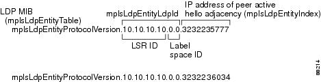
An LDP entity is uniquely identified by an LDP identifier that consists of the mplsLdpEntityLdpId and the mplsLdpEntityIndex (see Figure 1).
•![]() The mplsLdpEntityLdpId consists of the local LSR ID (four octets) and the label space ID (two octets). The label space ID identifies a specific label space available within the LSR.
The mplsLdpEntityLdpId consists of the local LSR ID (four octets) and the label space ID (two octets). The label space ID identifies a specific label space available within the LSR.
•![]() The mplsLdpEntityIndex consists of the IP address of the peer active hello adjacency, which is the 32-bit representation of the IP address assigned to the peer LSR.
The mplsLdpEntityIndex consists of the IP address of the peer active hello adjacency, which is the 32-bit representation of the IP address assigned to the peer LSR.
The mplsldpEntityProtocolVersion is a sample object from the mplsLdpEntityTable.
Figure 1 shows the following indexing:
•![]() mplsLdpEntityLdpId = 10.10.10.10.0.0
mplsLdpEntityLdpId = 10.10.10.10.0.0
•![]() LSR ID = 10.10.10.10
LSR ID = 10.10.10.10
•![]() Label space ID = 0.0
Label space ID = 0.0
The mplsLdpEntityLdpId or the LDP ID consists of the LSR ID and the label space ID.
•![]() The IP address of peer active hello adjacency or the mplsLdpEntityIndex = 3232235777, which is the 32-bit representation of the IP address assigned to the peer's active hello adjacency.
The IP address of peer active hello adjacency or the mplsLdpEntityIndex = 3232235777, which is the 32-bit representation of the IP address assigned to the peer's active hello adjacency.
Figure 1 Sample Indexing for an LDP Entity
An LDP entity represents a label space that has the potential for a session with an LDP peer. An LDP entity is set up when a hello adjacency receives a hello message from an LDP peer.
In Figure 2, Router A has potential sessions with two remote peers, Routers B and C. The mplsLdpEntityLdpId is 10.10.10.10.0.0, and the IP address of the peer active hello adjacency (mplsLdpEntityIndex) is 3232235777, which is the 32-bit representation of the IP address 192.168.1.1 for Router B.
Figure 2
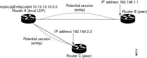
LDP Entity
LDP Sessions and Peers
LDP sessions exist between local entities and remote peers for the purpose of distributing label spaces. There is always a one-to-one correspondence between an LDP peer and an LDP session. A single LDP session is an LDP instance that communicates across one or more network links with a single LDP peer.
LDP supports the following types of sessions:
•![]() Interface-specific—An interface-specific session uses interface resources for label space distributions. For example, each label-controlled ATM (LC-ATM) interface uses its own VPIs/VCIs for label space distributions. Depending on its configuration, an LDP platform can support zero, one, or more interface-specific sessions. Each LC-ATM interface has its own interface-specific label space and a nonzero label space ID.
Interface-specific—An interface-specific session uses interface resources for label space distributions. For example, each label-controlled ATM (LC-ATM) interface uses its own VPIs/VCIs for label space distributions. Depending on its configuration, an LDP platform can support zero, one, or more interface-specific sessions. Each LC-ATM interface has its own interface-specific label space and a nonzero label space ID.
•![]() Platform-wide—An LDP platform supports a single platform-wide session for use by all interfaces that can share the same global label space. For Cisco platforms, all interface types except LC-ATM use the platform-wide session and have a label space ID of zero.
Platform-wide—An LDP platform supports a single platform-wide session for use by all interfaces that can share the same global label space. For Cisco platforms, all interface types except LC-ATM use the platform-wide session and have a label space ID of zero.
When a session is established between two peers, entries are created in the mplsLdpPeerTable and the mplsLdpSessionTable because they have the same indexing.
In Figure 3, Router A has two remote peers, Routers B and C. Router A has a single platform-wide session that consists of two serial interfaces with Router B and another platform-wide session with Router C. Router A also has two interface-specific sessions with Router B.
Figure 3
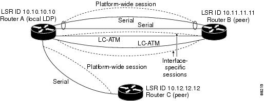
LDP Sessions
Figure 4 shows entries that correspond to the mplsLdpPeerTable and the mplsLdpSessionTable in Figure 3.
In Figure 4, mplsLdpSesState is a sample object from the mplsLdpSessionTable on Router A. There are four mplsLdpSesState sample objects shown (top to bottom). The first object represents a platform-wide session associated with two serial interfaces. The next two objects represent interface-specific sessions for the LC-ATM interfaces on Routers A and B. These interface-specific sessions have nonzero peer label space IDs. The last object represents a platform-wide session for the next peer, Router C.
The indexing is based on the entries in the mplsLdpEntityTable. It begins with the indexes of the mplsLdpEntityTable and adds the following:
•![]() Peer LDP ID = 10.11.11.11.0.0
Peer LDP ID = 10.11.11.11.0.0
The peer LDP ID consists of the peer LSR ID (four octets) and the peer label space ID (two octets).
•![]() Peer LSR ID = 10.11.11.11
Peer LSR ID = 10.11.11.11
•![]() Peer label space ID = 0.0
Peer label space ID = 0.0
The peer label space ID identifies a specific peer label space available within the LSR.
Figure 4
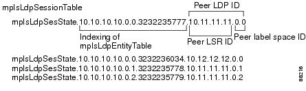
Sample Indexing for an LDP Session
LDP Hello Adjacencies
An LDP hello adjacency is a network link between a router and its peers. An LDP hello adjacency enables two adjacent peers to exchange label binding information.
An LDP hello adjacency exists for each link on which LDP runs. Multiple LDP hello adjacencies exist whenever there is more than one link in a session between a router and its peer, such as in a platform-wide session.
A hello adjacency is considered active if it is currently engaged in a session, or nonactive if it is not currently engaged in a session.
A targeted hello adjacency is not directly connected to its peer and has an unlimited number of hops between itself and its peer. A linked hello adjacency is directly connected between two routers.
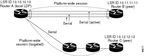
In Figure 5, Router A has two remote peers, Routers B and C. Router A has a platform-wide session with Router B that consists of three serial interfaces, one of which is active and another platform-wide (targeted) session with Router C.
Figure 5
Hello Adjacency
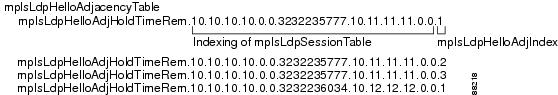
Figure 6 shows entries in the mplsLdpHelloAdjacencyTable. There are four
mplsLdpHelloAdjHoldTime sample objects (top to bottom). They represent the two platform-wide sessions and the four serial links shown in Figure 5.
The indexing is based on the mplsLdpSessionTable. When the mplsLdpHelloAdjIndex enumerates the different links within a single session, the active link is mplsLdpHelloAdjIndex = 1.
Figure 6
Sample Indexing for an LDP Hello Adjacency
Events Generating MPLS LDP MIB Notifications in MPLS LDP MIB Version 8 Upgrade
When you enable MPLS LDP MIB notification functionality by issuing the snmp-server enable traps mpls ldp command, notification messages are generated and sent to a designated NMS in the network to signal the occurrence of specific events within Cisco IOS.
The MPLS LDP MIB objects involved in LDP status transitions and event notifications include the following:
•![]() mplsLdpSessionUp—This message is generated when an LDP entity (a local LSR) establishes an LDP session with another LDP entity (an adjacent LDP peer in the network).
mplsLdpSessionUp—This message is generated when an LDP entity (a local LSR) establishes an LDP session with another LDP entity (an adjacent LDP peer in the network).
•![]() mplsLdpSessionDown—This message is generated when an LDP session between a local LSR and its adjacent LDP peer is terminated.
mplsLdpSessionDown—This message is generated when an LDP session between a local LSR and its adjacent LDP peer is terminated.
•![]() mplsLdpPathVectorLimitMismatch—This message is generated when a local LSR establishes an LDP session with its adjacent peer LSR, but the two LSRs have dissimilar path vector limits.
mplsLdpPathVectorLimitMismatch—This message is generated when a local LSR establishes an LDP session with its adjacent peer LSR, but the two LSRs have dissimilar path vector limits.
The value of the path vector limit can range from 0 through 255; a value of 0 indicates that loop detection is off; any value other than zero up to 255 indicates that loop detection is on and, in addition, specifies the maximum number of hops through which an LDP message can pass before a loop condition in the network is sensed.
We recommend that all LDP-enabled routers in the network be configured with the same path vector limit. Accordingly, the mplsLdpPathVectorLimitMismatch object exists in the MPLS LDP MIB to provide a warning message to the NMS when two routers engaged in LDP operations have different path vector limits.
Note ![]() This notification is generated only if the distribution method is downstream-on-demand.
This notification is generated only if the distribution method is downstream-on-demand.
•![]() mplsLdpFailedInitSessionThresholdExceeded—This message is generated when a local LSR and an adjacent LDP peer attempt to set up an LDP session between them, but fail to do so after a specified number of attempts. The default number of attempts is 8. This default value is implemented and cannot be changed.
mplsLdpFailedInitSessionThresholdExceeded—This message is generated when a local LSR and an adjacent LDP peer attempt to set up an LDP session between them, but fail to do so after a specified number of attempts. The default number of attempts is 8. This default value is implemented and cannot be changed.
Eight failed attempts to establish an LDP session between a local LSR and an LDP peer, due to any type of incompatibility between the devices, causes this notification message to be generated. Cisco routers support the same features across multiple platforms.
Therefore, the most likely incompatibility to occur between Cisco LSRs is a mismatch of their respective ATM VPI/VCI label ranges.
For example, if you specify a range of valid labels for an LSR that does not overlap the range of its adjacent LDP peer, the routers try eight times to create an LDP session between themselves before the mplsLdpFailedInitSessionThresholdExceeded notification is generated and sent to the NMS as an informational message.
The LSRs whose label ranges do not overlap continue their attempt to create an LDP session between themselves after the eight-retry threshold is exceeded.
In such cases, the LDP threshold exceeded notification alerts the network administrator about a condition in the network that might warrant attention.
RFC 3036, LDP Specification, details the incompatibilities that can exist between Cisco routers and/or other vendor LSRs in an MPLS network.
Among such incompatibilities, for example, are the following:
–![]() Nonoverlapping ATM VPI/VCI ranges (as noted above) or nonoverlapping Frame-Relay DLCI ranges between LSRs attempting to set up an LDP session
Nonoverlapping ATM VPI/VCI ranges (as noted above) or nonoverlapping Frame-Relay DLCI ranges between LSRs attempting to set up an LDP session
–![]() Unsupported label distribution method
Unsupported label distribution method
–![]() Dissimilar protocol data unit (PDU) sizes
Dissimilar protocol data unit (PDU) sizes
–![]() Dissimilar types of LDP feature support
Dissimilar types of LDP feature support
MIB Tables in MPLS LDP MIB Version 8 Upgrade
Version 8 of the MPLS LDP MIB consists of the following tables:
•![]() mplsLdpEntityTable (Table 1)—Contains entries for every active LDP hello adjacency. Nonactive hello adjacencies appear in the mplsLdpHelloAdjacencyTable, rather than this table. This table is indexed by the local LDP identifier for the interface and the IP address of the peer active hello adjacency. (See Figure 1.)
mplsLdpEntityTable (Table 1)—Contains entries for every active LDP hello adjacency. Nonactive hello adjacencies appear in the mplsLdpHelloAdjacencyTable, rather than this table. This table is indexed by the local LDP identifier for the interface and the IP address of the peer active hello adjacency. (See Figure 1.)
The advantage of showing the active hello adjacency instead of sessions in this table is that the active hello adjacency can exist even if an LDP session is not active (cannot be established). Previous implementations of the IETF MPLS-LDP MIB used sessions as the entries in this table. This approach was inadequate because as sessions went down, the entries in the entity table would disappear completely because the agent code could no longer access them. This resulted in the MIB failing to provide information about failed LDP sessions.
Directed adjacencies are also shown in this table. These entries, however, are always up administratively (adminStatus) and operationally (operStatus), because the adjacencies disappear if the directed session fails. Nondirected adjacencies might disappear from the MIB on some occasions, because adjacencies are deleted if the underlying interface becomes operationally down, for example.
•![]() mplsLdpEntityConfGenLRTable (Table 2)—Contains entries for every LDP-enabled interface that is in the global label space. (For Cisco, this applies to all interfaces except LC-ATM. LC-ATM entities are shown in the mplsLdpEntityConfAtmLRTable instead.) Indexing is the same as it is for the mplsLdpEntityTable, except two indexes have been added, mplsLdpEntityConfGenLRMin and mplsLdpEntityConfGenLRMax. These additional indexes allow more than one label range to be defined. However, in the current Cisco IOS implementation, only one global label range is allowed.
mplsLdpEntityConfGenLRTable (Table 2)—Contains entries for every LDP-enabled interface that is in the global label space. (For Cisco, this applies to all interfaces except LC-ATM. LC-ATM entities are shown in the mplsLdpEntityConfAtmLRTable instead.) Indexing is the same as it is for the mplsLdpEntityTable, except two indexes have been added, mplsLdpEntityConfGenLRMin and mplsLdpEntityConfGenLRMax. These additional indexes allow more than one label range to be defined. However, in the current Cisco IOS implementation, only one global label range is allowed.
•![]() mplsLdpEntityAtmParmsTable (Table 3)—Contains entries for every LDP-enabled LC-ATM interface. This table is indexed the same as the mplsLdpEntityTable although only LC-ATM interfaces are shown.
mplsLdpEntityAtmParmsTable (Table 3)—Contains entries for every LDP-enabled LC-ATM interface. This table is indexed the same as the mplsLdpEntityTable although only LC-ATM interfaces are shown.
•![]() mplsLdpEntityConfAtmLRTable (Table 4)—Contains entries for every LDP-enabled LC-ATM interface. Indexing is the same as it is for the mplsLdpEntityTable, except two indexes have been added, mplsLdpEntityConfAtmLRMinVpi and mplsLdpEntityConfAtmLRMinVci. These additional indexes allow more than one label range to be defined. However, in the current Cisco IOS implementation, only one label range per LC-ATM interface is allowed.
mplsLdpEntityConfAtmLRTable (Table 4)—Contains entries for every LDP-enabled LC-ATM interface. Indexing is the same as it is for the mplsLdpEntityTable, except two indexes have been added, mplsLdpEntityConfAtmLRMinVpi and mplsLdpEntityConfAtmLRMinVci. These additional indexes allow more than one label range to be defined. However, in the current Cisco IOS implementation, only one label range per LC-ATM interface is allowed.
•![]() mplsLdpEntityStatsTable (Table 5)—Augments the mplsLdpEntityTable and shares the exact same indexing for performing GET and GETNEXT operations. This table shows additional statistics for entities.
mplsLdpEntityStatsTable (Table 5)—Augments the mplsLdpEntityTable and shares the exact same indexing for performing GET and GETNEXT operations. This table shows additional statistics for entities.
•![]() mplsLdpPeerTable (Table 6)—Contains entries for all peer sessions. This table is indexed by the local LDP identifier of the session, the IP address of the peer active hello adjacency, and the peer's LDP identifier. (See Figure 4.)
mplsLdpPeerTable (Table 6)—Contains entries for all peer sessions. This table is indexed by the local LDP identifier of the session, the IP address of the peer active hello adjacency, and the peer's LDP identifier. (See Figure 4.)
•![]() mplsLdpHelloAdjacencyTable (Table 7)—Contains entries for all hello adjacencies. This table is indexed by the local LDP identifier of the associated session, the IP address of the peer active hello adjacency, the LDP identifier for the peer, and an arbitrary index that is set to the list position of the adjacency. (See Figure 6.)
mplsLdpHelloAdjacencyTable (Table 7)—Contains entries for all hello adjacencies. This table is indexed by the local LDP identifier of the associated session, the IP address of the peer active hello adjacency, the LDP identifier for the peer, and an arbitrary index that is set to the list position of the adjacency. (See Figure 6.)
•![]() mplsLdpSessionTable (Table 8)—Augments the mplsLdpPeerTable and shares the same indexing for performing GET and GETNEXT operations. This table shows all sessions.
mplsLdpSessionTable (Table 8)—Augments the mplsLdpPeerTable and shares the same indexing for performing GET and GETNEXT operations. This table shows all sessions.
•![]() mplsLdpAtmSesTable (Table 9)—Contains entries for LC-ATM sessions. Indexing is the same as it is for the mplsLdpPeerTable, except two indexes have been added, mplsLdpSesAtmLRLowerBoundVpi and mplsLdpSesAtmLRLowerBoundVci. These additional indexes allow more than one label range to be defined. However, in the current Cisco IOS implementation, only one label range per LC-ATM interface is allowed.
mplsLdpAtmSesTable (Table 9)—Contains entries for LC-ATM sessions. Indexing is the same as it is for the mplsLdpPeerTable, except two indexes have been added, mplsLdpSesAtmLRLowerBoundVpi and mplsLdpSesAtmLRLowerBoundVci. These additional indexes allow more than one label range to be defined. However, in the current Cisco IOS implementation, only one label range per LC-ATM interface is allowed.
•![]() mplsLdpSesStatsTable (Table 10)—Augments the mplsLdpPeerTable and shares the exact same indexing for performing GET and GETNEXT operations. This table shows additional statistics for sessions.
mplsLdpSesStatsTable (Table 10)—Augments the mplsLdpPeerTable and shares the exact same indexing for performing GET and GETNEXT operations. This table shows additional statistics for sessions.
mplsLdpEntityTable
Table 1 lists the mplsLdpEntityTable objects and their descriptions.
mplsLdpEntityConfGenLRTable
Table 2 lists the mplsLdpEntityConfGenLRTable objects and their descriptions.
mplsLdpEntityAtmParmsTable
Table 3 lists the mplsLdpEntityAtmParmsTable objects and their descriptions.
mplsLdpEntityConfAtmLRTable
Table 4 lists the mplsLdpEntityConfAtmLRTable objects and their descriptions.
mplsLdpEntityStatsTable
Table 5 lists the mplsLdpEntityStatsTable objects and their descriptions.
mplsLdpPeerTable
Table 6 lists the mplsLdpPeerTable objects and their descriptions.
mplsLdpHelloAdjacencyTable
Table 7 lists the mplsLdpHelloAdjacencyTable objects and their descriptions.
mplsLdpSessionTable
Table 8 lists the mplsLdpSessionTable objects and their descriptions.
mplsLdpAtmSesTable
Table 9 lists the mplsLdpAtmSesTable objects and their descriptions.
mplsLdpSesStatsTable
Table 10 lists the mplsLdpSesStatsTable objects and their descriptions.
VPN Contexts in MPLS LDP MIB Version 8 Upgrade
Within an MPLS Border Gateway Protocol (BGP) 4 Virtual Private Network (VPN) environment, separate LDP processes can be created for each VPN. These processes and their associated data are called LDP contexts. Each context is independent from all others and contains data specific only to that context.
Cisco IOS Release 12.0(11)ST and later releases include the VPN Aware LDP MIB feature that allows the LDP MIB to get VPN context information. The feature adds support for different contexts for different MPLS VPNs. Users of the MIB can view MPLS LDP processes for a given MPLS VPN. The VPN Aware LDP MIB feature does not change the syntax of the IETF MPLS-LDP MIB. It changes the number and types of entries within the tables.
The IETF MPLS-LDP MIB can show information about only one context at a time. You can specify a context, either a global context or an MPLS VPN context, using an SMNP security name.
The following sections describe topics related to the VPN Aware LDP MIB feature:
•![]() VPN Aware LDP MIB Notifications
VPN Aware LDP MIB Notifications
SNMP Contexts
SNMP contexts provide VPN users with a secure way of accessing MIB data. When a VPN is associated with a context, that VPN's specific MIB data exists in that context. Associating a VPN with a context enables service providers to manage networks with multiple VPNs. Creating and associating a context with a VPN enables a provider to prevent the users of one VPN from accessing information about users of other VPNs on the same networking device.
VPN-aware SNMP requires that SNMP manager and agent entities operating in a VPN environment agree on mapping between the SNMP security name and the VPN name. This mapping is created by using different contexts for the SNMP data of different VPNs, which is accomplished through the configuration of the SNMP View-based Access Control Model MIB (SNMP-VACM-MIB). The SNMP-VACM-MIB is configured with views so that a user on a VPN with a security name is allowed access to the restricted object space within the context of only that VPN.
SNMP request messages undergo three phases of security and access control before a response message is sent back with the object values within a VPN context:
•![]() The first security phase is authentication of the username. During this phase, the user is authorized for SNMP access.
The first security phase is authentication of the username. During this phase, the user is authorized for SNMP access.
•![]() The second phase is access control. During this phase, the user is authorized for SNMP access to the group objects in the requested SNMP context.
The second phase is access control. During this phase, the user is authorized for SNMP access to the group objects in the requested SNMP context.
•![]() In the third phase, the user can access a particular instance of a table entry. With this third phase, complete retrieval can be based on the SNMP context name.
In the third phase, the user can access a particular instance of a table entry. With this third phase, complete retrieval can be based on the SNMP context name.
IP access lists can be configured and associated with SNMP community strings. This feature enables you to configure an association between VRF instances and SNMP community strings. When a VRF instance is associated with an SNMP community string, SNMP processes requests coming in for a particular community string only if they are received from the configured VRF. If the community string contained in the incoming packet does not have a VRF associated with it, it is processed only if it came in through a non-VRF interface.
You can also enable or disable authentication traps for SNMP packets dropped due to VRF mismatches. By default, if SNMP authentication traps are enabled, VRF authentication traps are also enabled.
VPN Aware LDP MIB Sessions
Prior to Cisco IOS Release 12.0(11)ST, an SNMP query to the MPLS LDP MIB returned information about global sessions only. A query did not return information about LDP sessions in a VPN context. The IETF MPLS LDP MIB retrieved information from global routing tables, but did not retrieve information from VPN routing and forwarding instances (VRFs) that store per-VPN routing data. The MPLS LDP MIB looked only at LDP processes in the global context and ignored all other sessions. A query on a VRF returned no information. You can view LDP processes in a VPN context.
Figure 7 shows a sample MPLS VPN network with the MPLS LDP sessions prior to the implementation of the VPN Aware LDP MIB feature.
Figure 7 MPLS LDP Sessions Setup Before VPN Aware LDP MIB Feature
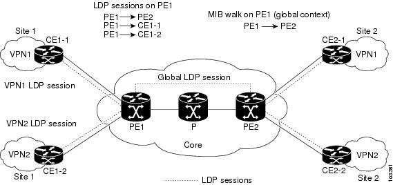
A MIB walk prior to this Cisco IOS release displayed only global session information.
With the VPN Aware LDP MIB enhancement in this Cisco IOS release, an SNMP query to the IETF MPLS-LDP-MIB supports both global and VPN contexts. This feature allows you to enter LDP queries on any VRF and on the core (global context). A query can differentiate between LDP sessions from different VPNs. LDP session information for a VPN stays in the context of that VPN. Therefore, the information from one VPN is not available to a user of a different VPN. The VPN Aware update to the LDP MIB also allows you to view LDP processes operating in a Carrier Supporting Carrier (CSC) network.
In an MPLS VPN, a service provider edge router (PE) might contain VRFs for several VPNs as well as a global routing table. To set up separate LDP processes for different VPNs on the same device, you need to configure each VPN with a unique securityName, contextName, and View-based Access Control Model (VACM) view. The VPN securityName must be configured for the IETF MPLS LDP MIB.
Figure 8 shows LDP sessions for a sample MPLS VPN network with the VPN Aware LDP MIB feature.
Figure 8 MPLS LDP Sessions with the VPN Aware LDP MIB Feature
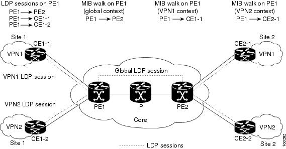
With the VPN Aware LDP MIB feature, you can do MIB queries or MIB walks for an MPLS VPN LDP session or a global LDP session.
Note ![]() To verify LDP session information for a specific VPN, use the show mpls ldp neighbor vrf vpn-name detail command.
To verify LDP session information for a specific VPN, use the show mpls ldp neighbor vrf vpn-name detail command.
VPN Aware LDP MIB Notifications
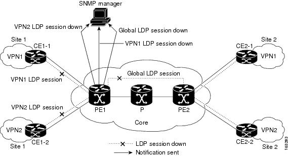
Prior to Cisco IOS Release 12.0(11)ST, all notification messages for MPLS LDP sessions were sent to the same designated network management station (NMS) in the network. The notifications were enabled with the snmp-server enable traps mpls ldp command.
Figure 9 shows LDP notifications that were sent before the implementation of the VPN Aware LDP MIB feature.
Figure 9 LDP Notifications Sent Before the VPN Aware LDP MIB Feature
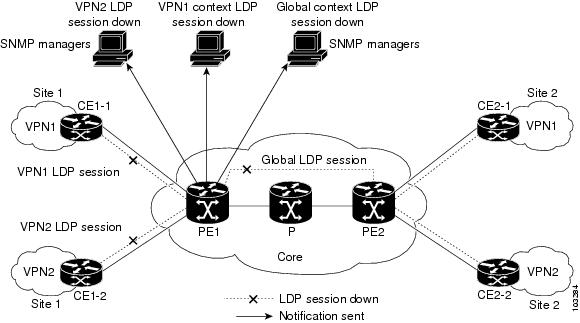
The VPN Aware LDP MIB feature supports LDP notifications for multiple LDP contexts for VPNs. LDP notifications can be generated for the core (global context) and for different VPNs. You can cause notifications be sent to different NMS hosts for different LDP contexts. LDP notifications associated with a specific VRF are sent to the NMS designated for that VRF. LDP global notifications are sent to the NMS configured to receive global traps.
To enable LDP context notifications for the VPN Aware LDP MIB feature, use either the SNMP object mplsLdpSessionsUpDownEnable (in the global LDP context only) or the following extended global configuration commands.
To enable LDP notifications for the global context, use the following commands:
PE-Router(config)# snmp-server host host-address traps community mpls-ldp
PE-Router(config)# snmp-server enable traps mpls ldp
To enable LDP notifications for a VPN context, use the following commands:
PE-Router(config)# snmp-server host host-address vrf vrf-name version {v1|v2c|v3}
community community-string udp-port upd-port mpls-ldp
PE-Router(config)# snmp-server enable traps mpls ldp
Figure 10 shows LDP notifications with the VPN Aware LDP MIB feature.
Figure 10 LDP Notifications With the VPN Aware LDP MIB Feature
How to Configure MPLS LDP MIB Version 8 Upgrade
This section contains the following procedures:
•![]() Enabling the SNMP Agent (required)
Enabling the SNMP Agent (required)
•![]() Enabling Cisco Express Forwarding (required)
Enabling Cisco Express Forwarding (required)
•![]() Enabling MPLS Globally (required)
Enabling MPLS Globally (required)
•![]() Enabling LDP Globally (required)
Enabling LDP Globally (required)
•![]() Enabling MPLS on an Interface (required)
Enabling MPLS on an Interface (required)
•![]() Enabling LDP on an Interface (required)
Enabling LDP on an Interface (required)
•![]() Configuring a VPN Aware LDP MIB (required)
Configuring a VPN Aware LDP MIB (required)
•![]() Verifying MPLS LDP MIB Version 8 Upgrade (optional)
Verifying MPLS LDP MIB Version 8 Upgrade (optional)
Enabling the SNMP Agent
Perform this task to enable the SNMP agent.
SUMMARY STEPS
1. ![]() enable
enable
2. ![]() show running-config
show running-config
3. ![]() configure terminal
configure terminal
4. ![]() snmp-server community string [view view-name] [ro] [number]
snmp-server community string [view view-name] [ro] [number]
5. ![]() end
end
6. ![]() write memory
write memory
DETAILED STEPS
Enabling Cisco Express Forwarding
Perform this task to enable Cisco Express Forwarding or distributed Cisco Express Forwarding.
SUMMARY STEPS
1. ![]() enable
enable
2. ![]() configure terminal
configure terminal
3. ![]() ip cef distributed
ip cef distributed
4. ![]() end
end
DETAILED STEPS
Enabling MPLS Globally
Perform this task to enable MPLS globally.
SUMMARY STEPS
1. ![]() enable
enable
2. ![]() configure terminal
configure terminal
3. ![]() mpls ip
mpls ip
4. ![]() end
end
DETAILED STEPS
Enabling LDP Globally
Perform this task to enable LDP globally.
SUMMARY STEPS
1. ![]() enable
enable
2. ![]() configure terminal
configure terminal
3. ![]() mpls label protocol {ldp | tdp}
mpls label protocol {ldp | tdp}
4. ![]() end
end
DETAILED STEPS
Enabling MPLS on an Interface
Perform this task to enable MPLS on an interface.
SUMMARY STEPS
1. ![]() enable
enable
2. ![]() configure terminal
configure terminal
3. ![]() interface [type number]
interface [type number]
4. ![]() mpls ip
mpls ip
5. ![]() end
end
DETAILED STEPS
Enabling LDP on an Interface
Perform this task to enable LDP on an interface.
SUMMARY STEPS
1. ![]() enable
enable
2. ![]() configure terminal
configure terminal
3. ![]() interface [type number]
interface [type number]
4. ![]() mpls label protocol {ldp | tdp | both}
mpls label protocol {ldp | tdp | both}
5. ![]() end
end
DETAILED STEPS
Configuring a VPN Aware LDP MIB
To configure a VPN Aware LDP MIB, perform the following tasks:
•![]() Configuring SNMP Support for a VPN
Configuring SNMP Support for a VPN
•![]() Configuring an SNMP Context for a VPN
Configuring an SNMP Context for a VPN
•![]() Associating an SNMP VPN Context with SNMPv1 or SNMPv2
Associating an SNMP VPN Context with SNMPv1 or SNMPv2
Configuring SNMP Support for a VPN
Perform this task to configure SNMP support for a Virtual Private Network (VPN) or a remote VPN.
SUMMARY STEPS
1. ![]() enable
enable
2. ![]() configure terminal
configure terminal
3. ![]() snmp-server host host-address [traps | informs] [version {1 | 2c | 3 [auth | noauth | priv]}]
snmp-server host host-address [traps | informs] [version {1 | 2c | 3 [auth | noauth | priv]}]
community-string [udp-port port] [notification-type] [vrf vrf-name]
4. ![]() snmp-server engineID remote ip-address [udp-port udp-port-number] [vrf vrf-name]
snmp-server engineID remote ip-address [udp-port udp-port-number] [vrf vrf-name]
engineid-string
5. ![]() end
end
DETAILED STEPS
What to Do Next
Proceed to the "Configuring an SNMP Context for a VPN" section.
Configuring an SNMP Context for a VPN
Perform this task to configure an SNMP context for a VPN. This sets up a unique SNMP context for a VPN, which allows you to access the VPN's LDP session information.
SNMP Context
SNMP contexts provide VPN users with a secure way of accessing MIB data. When a VPN is associated with a context, that VPN's specific MIB data exists in that context. Associating a VPN with a context enables service providers to manage networks with multiple VPNs. Creating and associating a context with a VPN enables a provider to prevent the users of one VPN from accessing information about users of other VPNs on the same networking device.
VPN Route Distinguishers
A route distinguisher (RD) creates routing and forwarding tables for a VPN. Cisco IOS adds the RD to the beginning of the customer's IPv4 prefixes to change them into globally unique VPN-IPv4 prefixes.
Either the RD is an autonomous system number (ASN)-relative RD, in which case it is composed of an autonomous system number and an arbitrary number, or it is an IP-address-relative RD, in which case it is composed of an IP address and an arbitrary number. You can enter an RD in either of these formats:
•![]() 16-bit ASN: your 32-bit number, for example, 101:3.
16-bit ASN: your 32-bit number, for example, 101:3.
•![]() 32-bit IP address: your 16-bit number, for example, 192.168.122.15:1.
32-bit IP address: your 16-bit number, for example, 192.168.122.15:1.
SUMMARY STEPS
1. ![]() enable
enable
2. ![]() configure terminal
configure terminal
3. ![]() snmp-server context context-name
snmp-server context context-name
4. ![]() ip vrf vrf-name
ip vrf vrf-name
5. ![]() rd route-distinguisher
rd route-distinguisher
6. ![]() context context-name
context context-name
7. ![]() route-target {import | export | both} route-target-ext-community
route-target {import | export | both}
route-target-ext-community
8. ![]() end
end
DETAILED STEPS
What to Do Next
Proceed to the "Associating an SNMP VPN Context with SNMPv1 or SNMPv2" section.
Associating an SNMP VPN Context with SNMPv1 or SNMPv2
Perform this task to associate an SNMP VPN context with SNMPv1 or SNMPv2. This allows you to access LDP session information for a VPN using SNMPv1 or SNMPv2.
SNMPv1 or SNMPv2 Security
SNMPv1 and SNMPv2 are not as secure as SNMPv3. SNMP Versions 1 and 2 use plain text communities and do not perform the authentication or security checks that SNMP Version 3 performs.
To configure the VPN Aware LDP MIB feature when using SNMP Version 1 or SNMP Version 2, you need to associate a community name with a VPN. This association causes SNMP to process requests coming in for a particular community string only if they come in from the configured VRF. If the community string contained in the incoming packet does not have an associated VRF, the packet is processed only if it came in through a non-VRF interface. This process prevents users outside the VPN from using a clear text community string to query the VPN data. However, this is not as secure as using SNMPv3.
SUMMARY STEPS
1. ![]() enable
enable
2. ![]() configure terminal
configure terminal
3. ![]() snmp-server user username group-name [remote host [udp-port port]] {v1 | v2c | v3 [encrypted]
snmp-server user username group-name [remote host [udp-port port]] {v1 | v2c | v3 [encrypted]
[auth {md5 | sha} auth-password]} [access access-list]
4. ![]() snmp-server group group-name {v1 | v2c | v3 {auth | noauth | priv}} [context context-name]
snmp-server group group-name {v1 | v2c | v3 {auth | noauth | priv}} [context context-name]
[read readview] [write writeview] [notify notifyview] [access access-list]
5. ![]() snmp-server view view-name oid-tree {included | excluded}
snmp-server view view-name oid-tree {included | excluded}
6. ![]() snmp-server enable traps [notification-type]
snmp-server enable traps [notification-type]
7. ![]() snmp-server host host-address [traps | informs] [version {1 | 2c | 3 [auth | noauth | priv]}]
snmp-server host host-address [traps | informs] [version {1 | 2c | 3 [auth | noauth | priv]}]
community-string [udp-port port] [notification-type] [vrf vrf-name]
8. ![]() snmp mib community-map community-name [context context-name] [engineid engine-id]
snmp mib community-map community-name [context context-name] [engineid engine-id]
[security-name security-name] target-list vpn-list-name
9. ![]() snmp mib target list vpn-list-name {vrf vrf-name | host ip-address}
snmp mib target list vpn-list-name {vrf vrf-name | host ip-address}
10. ![]() no snmp-server trap authentication vrf
no snmp-server trap authentication vrf
11. ![]() exit
exit
DETAILED STEPS
Verifying MPLS LDP MIB Version 8 Upgrade
Perform a MIB walk using your SNMP management tool to verify that the MPLS LDP MIB Version 8 Upgrade feature is functioning.
Configuration Examples for MPLS LDP MIB Version 8 Upgrade
This section provides the following configuration examples:
•![]() MPLS LDP MIB Version 8 Upgrade Examples
MPLS LDP MIB Version 8 Upgrade Examples
•![]() Configuring a VPN Aware SNMP Context for SNMPv1 or SNMPv2: Example
Configuring a VPN Aware SNMP Context for SNMPv1 or SNMPv2: Example
MPLS LDP MIB Version 8 Upgrade Examples
The following example shows how to enable an SNMP agent on the host NMS:
Router# configure terminal
Enter configuration commands, one per line. End with CNTL/Z.
Router(config)# snmp-server community
The following example shows how to enable SNMPv1 and SNMPv2C on the host NMS. The configuration permits any SNMP agent to access all MPLS LDP MIB objects that have read-only permission using the community string public.
Router(config)# snmp-server community public
The following example shows how to allow read-only access to all MPLS LDP MIB objects relating to members of access list 4 that specify the comaccess community string. No other SNMP agents will have access to any of the MPLS LDP MIB objects.
Router(config)# snmp-server community comaccess ro 4
The following example shows how to enable LDP globally and then on an interface:
Router# configure terminal
Enter configuration commands, one per line. End with CNTL/Z.
Router(config)# mpls label protocol ldp
Router(config)# interface Ethernet1
Router(config-if)# mpls label protocol ldp
Router(config-if)# end
Configuring a VPN Aware SNMP Context for SNMPv1 or SNMPv2: Example
The following configuration example shows how to configure a VPN Aware SNMP context for the MPLS LDP MIB Version 8 with SNMPv1 or SNMPv2:
snmp-server context A
snmp-server context B
ip vrf CustomerA
rd 100:110
context A
route-target export 100:1000
route-target import 100:1000
!
ip vrf CustomerB
rd 100:120
context B
route-target export 100:2000
route-target import 100:2000
!
interface Ethernet3/1
description Belongs to VPN A
ip vrf forwarding CustomerA
ip address 10.0.0.0 255.255.0.0
interface Ethernet3/2
description Belongs to VPN B
ip vrf forwarding CustomerB
ip address 10.0.0.1 255.255.0.0
snmp-server user commA grp1A v1
snmp-server user commA grp2A v2c
snmp-server user commB grp1B v1
snmp-server user commB grp2B v2c
snmp-server group grp1A v1 context A read viewA write viewA notify viewA
snmp-server group grp1B v1 context B read viewB write viewB notify viewB
snmp-server view viewA ipForward included
snmp-server view viewA ciscoPingMIB included
snmp-server view viewB ipForward included
snmp-server view viewB ciscoPingMIB included
snmp-server enable traps
snmp-server host 10.0.0.3 vrf CustomerA commA udp-port 7002
snmp-server host 10.0.0.4 vrf CustomerB commB udp-port 7002
snmp mib community-map commA context A target-list commAvpn
! Configures source address validation
snmp mib community-map commB context B target-list commBvpn
! Configures source address validation
snmp mib target list commAvpn vrf CustomerA
! Configures a list of VRFs or from which community commA is valid
snmp mib target list commBvpn vrf CustomerB
! Configures a list of VRFs or from which community commB is valid
Additional References
Related Documents
|
|
|
|---|---|
MPLS LDP configuration tasks |
Standards
|
|
|
|---|---|
No new or modified standards are supported by this feature, and support for existing standards has not been modified by this feature. |
— |
MIBs
RFCs
Technical Assistance
Command Reference
The following commands are introduced or modified in the feature or features documented in this module. For information about these commands, see the Cisco IOS Multiprotocol Label Switching Command Reference at http://www.cisco.com/en/US/docs/ios/mpls/command/reference/mp_book.html. For information about all Cisco IOS commands, go to the Command Lookup Tool at http://tools.cisco.com/Support/CLILookup or to the Cisco IOS Master Commands List.
•![]() context
context
•![]() show mpls ldp neighbor
show mpls ldp neighbor
•![]() snmp mib community-map
snmp mib community-map
•![]() snmp mib target list
snmp mib target list
•![]() snmp-server community
snmp-server community
•![]() snmp-server context
snmp-server context
•![]() snmp-server enable traps (MPLS)
snmp-server enable traps (MPLS)
•![]() snmp-server group
snmp-server group
•![]() snmp-server host
snmp-server host
•![]() snmp-server trap authentication vrf
snmp-server trap authentication vrf
Glossary
ATM—Asynchronous Transfer Mode. The international standard for cell relay in which multiple service types (such as voice, video, or data) are conveyed in fixed-length (53-byte) cells. Fixed-length cells allow cell processing to occur in hardware, thereby reducing transit delays. ATM is designed to take advantage of high-speed transmission media, such as E3, SONET, and T3.
downstream-on-demand distribution—A label distribution method in which a downstream label switch router (LSR) sends a binding upstream only if the upstream LSR requests it.
downstream unsolicited distribution—A label distribution method in which labels are dispersed if a downstream label switch router (LSR) needs to establish a new binding with its neighboring upstream LSR. For example, an edge LSR might enable a new interface with another subnet. The LSR then announces to the upstream router a binding to reach this network.
informs—A type of notification message that is more reliable than a conventional trap notification message, because the informs message notification requires acknowledgment, but a trap notification does not.
label—A short, fixed-length data identifier that tells switching nodes how to forward data (packets or cells).
label distribution—The techniques and processes that are used by label switch routers (LSRs) to exchange label binding information for supporting hop-by-hop forwarding along normally routed paths.
LDP—Label Distribution Protocol. The protocol that supports MPLS hop-by-hop forwarding and the distribution of bindings between labels and network prefixes. The Cisco proprietary version of this protocol is the Tag Distribution Protocol (TDP).
LSP—label-switched path. A configured connection between two label switch routers (LSRs) in which label-switching techniques are used for packet forwarding; also a specific path through an MPLS network.
LSR—label switch router. A Multiprotocol Label Switching (MPLS) node that can forward native Layer 3 packets. The LSR forwards a packet based on the value of a label attached to the packet.
MIB—Management Information Base. A database of network management information that is used and maintained by a network management protocol such as Simple Network Management Protocol (SNMP). The value of a MIB object can be changed or retrieved by the use of SNMP commands, usually through a network management system. MIB objects are organized in a tree structure that includes public (standard) and private (proprietary) branches.
MPLS—Multiprotocol Label Switching. A switching method for the forwarding of IP traffic through the use of a label. This label instructs the routers and the switches in the network where to forward the packets based on preestablished IP routing information.
MPLS label distribution—A constraint-based routing algorithm for routing label-switched path (LSP) tunnels.
NMS—network management station. A powerful, well-equipped computer (typically an engineering workstation) that is used by a network administrator to communicate with other devices in the network. An NMS is typically used to manage network resources, gather statistics, and perform a variety of network administration and configuration tasks. In the context of SNMP, an NMS is a device that performs SNMP queries to the SNMP agent of a managed device to retrieve or modify information.
notification—A message sent by a Simple Network Management Protocol (SNMP) agent to a network management station, console, or terminal to indicate that a significant network event has occurred. See also trap.
RSVP—Resource Reservation Protocol. A protocol that supports the reservation of resources across an IP network. Applications running on IP end systems can use RSVP to indicate to other nodes the nature of the packet streams they want to receive by specifying such items as bandwidth, jitter, and maximum burst.
RTR—Response Time Reporter. A tool that allows you to monitor network performance, network resources, and applications by measuring response times and availability.
SNMP—Simple Network Management Protocol. A network management protocol used almost exclusively in TCP/IP networks. SNMP enables a user to monitor and control network devices, manage configurations, collect statistics, monitor performance, and ensure network security.
SNMP communities—Authentication scheme that enables an intelligent network device to validate SNMP requests.
SNMPv2c—Version 2c of the Simple Network Management Protocol. SNMPv2c supports centralized as well as distributed network management strategies and includes improvements in the Structure of Management Information (SMI), protocol operations, management architecture, and security.
SNMPv3—Version 3 of the Simple Network Management Protocol. Interoperable standards-based protocol for network management. SNMPv3 provides secure access to devices by a combination of authenticating and encrypting packets over the network.
TDP—Tag Distribution Protocol. A standard protocol used by MPLS-enabled routers to negotiate the tags (addresses) used for forwarding packets. See also LDP.
TLV—Type-Length-Value. A mechanism used by several routing protocols to carry a variety of attributes. Cisco Discovery Protocol (CDP), Label Discovery Protocol (LDP), and Border Gateway Protocol (BGP) are examples of protocols that use TLVs. BGP uses TLVs to carry attributes such as Network Layer Reachability Information (NLRI), Multiple Exit Discriminator (MED), and local preference.
trap—A message sent by an SNMP agent to a network management station, console, or terminal to indicate that a significant network event has occurred. Traps (notifications) are less reliable than inform requests, because the receiver of the trap does not send an acknowledgment of receipt; furthermore, the sender of the trap cannot determine if the trap was received. See also notification.
VCC—virtual channel connection. A logical circuit, made up of virtual channel links (VCLs), that carries data between two endpoints in an ATM network. Sometimes called a virtual circuit connection.
VCI—virtual channel identifier. A 16-bit field in the header of an ATM cell. The VCI, together with the virtual path identifier (VPI), is used to identify the next network virtual channel link (VCL) as the cell passes through a series of ATM switches on its way to its final destination.
VCL—virtual channel link. The logical connection that exists between two adjacent switches in an ATM network.
VPI—virtual path identifier. An 8-bit field in the header of an ATM cell. The VPI, together with the virtual channel identifier (VCI), is used to identify the next network virtual channel link (VCL) as the cell passes through a series of ATM switches on its way to its final destination.
VPN—Virtual Private Network. A network that enables IP traffic to use tunneling to travel securely over a public TCP/IP network.
VRF—VPN routing and forwarding instance. A VRF consists of an IP routing table, a derived forwarding table, a set of interfaces that use the forwarding table, and a set of rules and routing protocols that determine what goes into the forwarding table. In general, a VRF includes the routing information that defines a customer VPN site that is attached to a PE router.

 Feedback