16- and 36-Port Cisco EtherSwitch Network Module for Cisco 2600 Series, Cisco 3600 Series, and Cisco 3700 Series
Available Languages
Table Of Contents
Switch Virtual Interfaces (SVI)
Maximum Number of VLAN and Multicast Groups
IGMP snooping Versions 1 and 2
Ethernet Switching in Cisco AVVID Architecture
Related Features and Technologies
Supported Standards, MIBs, and RFCs
Configuring Layer 2 Interfaces
Configuring a Range of Interfaces
Verifying Configuration of a Range of Interfaces
Configuring Layer 2 Optional Interface Features
Interface Speed and Duplex Configuration Guidelines
Configuring the Interface Speed
Configuring the Interface Duplex Mode
Verifying Interface Speed and Duplex Mode Configuration
Configuring a Description for an Interface
Configuring an Ethernet Interface as a Layer 2 Trunk
Verifying an Ethernet Interface as a Layer 2 Trunk
Configuring an Ethernet Interface as a Layer 2 Access
Verifying an Ethernet Interface as a Layer 2 Access
Verifying the VLAN Configuration.
Deleting a VLAN from the Database
Configuring VLAN Trunking Protocol (VTP)
Disabling VTP (VTP Transparent Mode)
Configuring Layer 2 EtherChannels (Port-Channel Logical Interfaces)
Configuring Layer 2 EtherChannels (Port-Channel Logical Interfaces)
Verifying Layer 2 EtherChannels
Configuring EtherChannel Load Balancing
Verifying EtherChannel Load Balancing
Removing an Interface from an EtherChannel
Configuring Removing an EtherChannel
Verify Removing an EtherChannel
Configuring Spanning Tree Port Priority
Verify Spanning Tree Port Priority
Configuring Spanning Tree Port Cost
Verifying Spanning Tree Port Cost
Configuring the Bridge Priority of a VLAN
Verifying the Bridge Priority of a VLAN
Configuring the Forward-Delay Time for a VLAN
Configuring the Maximum Aging Time for a VLAN
Verifying that Spanning Tree is Disabled.
Configuring Mac Table Manipulation — Port Security
Enabling Known MAC Address Traffic
Verifying the mac-address-table secure
Creating a Static or Dynamic Entry in the MAC Address Table
Verifying the mac-address-table
Configuring Cisco Discovery Protocol (CDP)
Configuring Cisco Discovery Protocol (CDP)
Verifying the CDP Global Configuration
Verifying the CDP Interface Configuration
Monitoring and Maintaining CDP
Configuring Switched Port Analyzer (SPAN)
Removing Sources or Destinations from a SPAN Session
Configuring Power Management on the Interface
Verifying Power Management on the Interface
Verifying Other Power Management CLI
Configuring IP Multicast Layer 3 Switching
Enabling IP Multicast Routing Globally
Enabling IP PIM on Layer 3 Interfaces
Verifying IP Multicast Layer 3 Hardware Switching Summary
Verifying the IP Multicast Routing Table
Default Storm-Control Configuration
Configuring Separate Voice and Data VLANs
Configuring a Single Subnet for Voice and Data
Verifying Switchport Configuration
Configuring Ethernet Ports to Support Cisco IP Phones with Multiple Ports
Managing the Ethernet switch network module
Assigning IP Information to the Switch
Specifying a Domain Name and Configuring the DNS
Configuring a Port to Connect to a Cisco 7960 IP phone
Verifying Voice Traffic Configuration
Disabling Inline Power on a Ethernet switch network module
Verifying Inline Power Configuration
Enabling Switch Port Analyzer (SPAN)
Managing the MAC Address Tables
Changing the Address Aging Time
Verifying Aging-Time Configuration
Clearing all MAC Address Tables
Configuring Intrachassis Stacking
Verifying Intra-chassis Stacking
Configuring Flow Control on Gigabit Ethernet Ports
Single Range Configuration Example
Multiple Range Configuration Example
Range Macro Definition Example
Optional Interface Feature Examples
Setting the Interface Duplex Mode Example
Adding a Description for an Interface Example
Configuring an Ethernet Interface as a Layer 2 Trunk Example
Disabling VTP (VTP Transparent Mode) Example
EtherChannel Load Balancing Example
EtherChannel Load Balancing Example
Removing an EtherChannel Example
Spanning-Tree Interface and Spanning-Tree Port Priority Example
Spanning-Tree Port Cost Example
Forward-Delay Time for a VLAN Example
Maximum Aging Time for a VLAN Example
Mac Table Manipulation Examples
Cisco Discovery Protocol (CDP) Example
Switched Port Analyzer (SPAN) Source Examples
SPAN Source Configuration Example
Removing Sources or Destinations from a SPAN Session Example
Subnets for Voice and Data Example
Single Subnet Configuration Example
Ethernet Ports on IP Phones with Multiple Ports Example
Flow Control on Gigabit Ethernet Ports Example
16- and 36-Port Cisco EtherSwitch Network Module for Cisco 2600 Series, Cisco 3600 Series, and Cisco 3700 Series
Feature History
This feature module describes the 16- and 36-Port Cisco EtherSwitch Network Module (NM-16ESW and NM-36ESW) for Cisco 2600 series, Cisco 3600 series, and Cisco 3700 series routers in Cisco IOS Release 12.2(2)XT and Cisco IOS Release 12.2(8)T and above.
This document includes the following sections:
•
Supported Standards, MIBs, and RFCs
Feature Overview
This document explains how to configure the 16- and 36-port Cisco EtherSwitch network modules. This network module is supported on Cisco 2600 series, Cisco 3600 series, and Cisco 3700 series routers. The Cisco EtherSwitch network module is a modular, high density voice network module that provides layer 2 switching across Ethernet ports. The 16-port Cisco EtherSwitch network module has 16 10/100BASE-TX ports and an optional 10/100/1000BASE-T Gigabit Ethernet port. The 36-port Cisco EtherSwitch network module has 36 10/100BASE-TX ports and two optional 10/100/1000BASE-T Gigabit Ethernet ports. The gigabit Ethernet can be used as an uplink port to a server or, as a stacking link to another 16- or 36-port Cisco EtherSwitch network modules in the same system. The 36-port Cisco EtherSwitch network module requires a double-wide slot. An optional power module can also be added to provide inline power for IP telephones.
The 16- and 36-port Cisco EtherSwitch network modules support the following:
•
•
•
•
Layer 2 Ethernet Interfaces
Layer 2 Ethernet Switching
Cisco EtherSwitch network modules support simultaneous, parallel connections between Layer 2 Ethernet segments. Switched connections between Ethernet segments last only for the duration of the packet. New connections can be made between different segments for the next packet.
The Cisco EtherSwitch network module solves congestion problems caused by high-bandwidth devices and a large number of users by assigning each device (for example, a server) to its own 10-, 100-, or 1000-Mbps segment. Because each Ethernet interface on the switch represents a separate Ethernet segment, servers in a properly configured switched environment achieve full access to the bandwidth.
Because collisions are a major bottleneck in Ethernet networks, an effective solution is full-duplex communication. Normally, Ethernet operates in half-duplex mode, which means that stations can either receive or transmit. In full-duplex mode, two stations can transmit and receive at the same time. When packets can flow in both directions simultaneously, effective Ethernet bandwidth doubles to 20 Mbps for 10-Mbps interfaces and to 200 Mbps for Fast Ethernet interfaces.
Switching Frames Between Segments
Each Ethernet interface on an Cisco EtherSwitch network module can connect to a single workstation or server, or to a hub through which workstations or servers connect to the network.
On a typical Ethernet hub, all ports connect to a common backplane within the hub, and the bandwidth of the network is shared by all devices attached to the hub. If two stations establish a session that uses a significant level of bandwidth, the network performance of all other stations attached to the hub is degraded.
To reduce degradation, the switch treats each interface as an individual segment. When stations on different interfaces need to communicate, the switch forwards frames from one interface to the other at wire speed to ensure that each session receives full bandwidth.
To switch frames between interfaces efficiently, the switch maintains an address table. When a frame enters the switch, it associates the MAC address of the sending station with the interface on which it was received.
Building the Address Table
The Cisco EtherSwitch network module builds the address table by using the source address of the frames received. When the switch receives a frame for a destination address not listed in its address table, it floods the frame to all interfaces of the same virtual local area network (VLAN) except the interface that received the frame. When the destination station replies, the switch adds its relevant source address and interface ID to the address table. The switch then forwards subsequent frames to a single interface without flooding to all interfaces. The address table can store at least 8,191 address entries without flooding any entries. The switch uses an aging mechanism, defined by a configurable aging timer; so if an address remains inactive for a specified number of seconds, it is removed from the address table.

Note
VLAN Trunks
A trunk is a point-to-point link between one or more Ethernet switch interfaces and another networking device such as a router or a switch. Trunks carry the traffic of multiple VLANs over a single link and allow you to extend VLANs across an entire network and supports only one encapsulation on all Ethernet interfaces:
802.1Q-802.1Q is an industry-standard trunking encapsulation.
You can configure a trunk on a single Ethernet interface or on an EtherChannel bundle. For more information about EtherChannel, see the "Configuring Layer 2 EtherChannels (Port-Channel Logical Interfaces)" section.
Layer 2 Interface Modes
Switchport mode access puts the interface into nontrunking mode. The interface will stay in access mode regardless of what the connected port mode is. Only access VLAN traffic will travel on the access port and untagged (802.3).
Switchport mode trunk puts the interface into permanent trunking mode.
Table 1 Default Layer 2 Ethernet Interface Configuration
When you connect a Cisco switch to a device other than a Cisco device through an 802.1Q trunk, the Cisco switch combines the spanning tree instance of the VLAN trunk with the spanning tree instance of the other 802.1Q switch. However, spanning tree information for each VLAN is maintained by Cisco switches separated by a cloud of 802.1Q switches that are not Cisco switches. The 802.1Q cloud separating the Cisco switches that is not Cisco devised, is treated as a single trunk link between the switches.
Make sure that the native VLAN for an 802.1Q trunk is the same on both ends of the trunk link. If the VLAN on one end of the trunk is different from the VLAN on the other end, spanning tree loops might result. Inconsistencies detected by a Cisco switch mark the line as broken and block traffic for the specific VLAN.
Disabling spanning tree on the VLAN of an 802.1Q trunk without disabling spanning tree on every VLAN in the network can potentially cause spanning tree loops. Cisco recommends that you leave spanning tree enabled on the VLAN of an 802.1Q trunk or that you disable spanning tree on every VLAN in the network. Make sure that your network is loop-free before disabling spanning tree.
Layer 2 Interface Configuration Guidelines and Restrictions
Switch Virtual Interfaces (SVI)
A switch virtual interface (SVI) represents a VLAN of switch ports as one interface to the routing or bridging function in the system. Only one SVI can be associated with a VLAN, but it is necessary to configure an SVI for a VLAN only when you wish to route between VLANs, fallback-bridge nonroutable protocols between VLANs, or to provide IP host connectivity to the switch. By default, an SVI is created for the default VLAN (VLAN 1) to permit remote switch administration. Additional SVIs must be explicitly configured. In Layer 2 mode, SVIs provide IP host connectivity only to the system; in Layer 3 mode, you can configure routing across SVIs.
To use SVIs in Layer 3 mode, you must have the enhanced multilayer switch image installed on your switch.
SVIs are created the first time that you enter the vlan interface configuration command for a VLAN interface. The VLAN corresponds to the VLAN tag associated with data frames on an ISL or 802.1Q encapsulated trunk or the VLAN ID configured for an access port. Configure a VLAN interface for each VLAN for which you want to route traffic, and assign it an IP address.
SVIs support routing protocol and bridging configurations. For more information about configuring IP routing, see the "Configuring IP Multicast Layer 3 Switching" section.
VLAN Trunk Protocol
VLAN Protocol (VTP) is a Layer 2 messaging protocol that maintains VLAN configuration consistency by managing the addition, deletion, and renaming of VLANs within a VTP domain. A VTP domain (also called a VLAN management domain) is made up of one or more switches that share the same VTP domain name and that are interconnected with trunks. VTP minimizes misconfigurations and configuration inconsistencies that can result in a number of problems, such as duplicate VLAN names, incorrect VLAN-type specifications, and security violations. Before you create VLANs, you must decide whether to use VTP in your network. With VTP, you can make configuration changes centrally on one or more switches and have those changes automatically communicated to all the other switches in the network.
VTP Domain
A VTP domain (also called a VLAN management domain) is made up of one or more interconnected switches that share the same VTP domain name. A switch can be configured to be in one and only one VTP domain. You make global VLAN configuration changes for the domain using either the command-line interface (CLI) or Simple Network Management Protocol (SNMP).
By default, the switch is in VTP server mode and is in an un-named domain state until the switch receives an advertisement for a domain over a trunk link or until you configure a management domain. You cannot create or modify VLANs on a VTP server until the management domain name is specified or learned.
If the switch receives a VTP advertisement over a trunk link, it inherits the management domain name and the VTP configuration revision number. The switch ignores advertisements with a different management domain name or an earlier configuration revision number.
If you configure the switch as VTP transparent, you can create and modify VLANs but the changes affect only the individual switch.
When you make a change to the VLAN configuration on a VTP server, the change is propagated to all switches in the VTP domain. VTP advertisements are transmitted out all trunk connections using IEEE 802.1Q encapsulation.
VTP maps VLANs dynamically across multiple LAN types with unique names and internal index associations. Mapping eliminates excessive device administration required from network administrators.
VTP Modes
You can configure a switch to operate in any one of these VTP modes:
•
•
•
VTP Advertisements
Each switch in the VTP domain sends periodic advertisements out each trunk interface to a reserved multicast address. VTP advertisements are received by neighboring switches, which update their VTP and VLAN configurations as necessary.
The following global configuration information is distributed in VTP advertisements:
•
•
•
•
•
VTP Version 2
If you use VTP in your network, you must decide whether to use VTP version 1 or version 2. VTP version 2 supports the following features not supported in version 1:
Unrecognized Type-Length-Value (TLV) Support—A VTP server or client propagates configuration changes to its other trunks, even for TLVs it is not able to parse. The unrecognized TLV is saved in NVRAM.
Version-Dependent Transparent Mode—In VTP version 1, a VTP transparent switch inspects VTP messages for the domain name and version, and forwards a message only if the version and domain name match. Since only one domain is supported in the NM-16ESW software, VTP version 2 forwards VTP messages in transparent mode, without checking the version.
Consistency Checks—In VTP version 2, VLAN consistency checks (such as VLAN names and values) are performed only when you enter new information through the CLI or SNMP. Consistency checks are not performed when new information is obtained from a VTP message, or when information is read from NVRAM. If the digest on a received VTP message is correct, its information is accepted without consistency checks.
VTP Configuration Guidelines and Restrictions
Follow these guidelines and restrictions when implementing VTP in your network:
•
•
•
•
•
•
•
EtherChannel
EtherChannel bundles up to eight individual Ethernet links into a single logical link that provides bandwidth of up to 1600 Mbps (Fast EtherChannel full duplex) between the network module and another switch or host.
A Cisco EtherSwitch network module system supports a maximum of six EtherChannels. All interfaces in each EtherChannel must have the same speed duplex and mode.
Load Balancing
EtherChannel balances traffic load across the links in a channel by reducing part of the binary pattern formed from the addresses in the frame to a numerical value that selects one of the links in the channel.
EtherChannel load balancing can use MAC addresses, or IP addresses; either source or destination or both source and destination. The selected mode applies to all EtherChannels configured on the switch.
Use the option that provides the greatest variety in your configuration. For example, if the traffic on a channel is going only to a single MAC address, using the destination MAC address always chooses the same link in the channel; using source addresses or IP addresses may result in better load balancing.
EtherChannel Configuration Guidelines and Restrictions
If improperly configured, some EtherChannel interfaces are disabled automatically to avoid network loops and other problems. Follow these guidelines and restrictions to avoid configuration problems:
•
Configure all interfaces in an EtherChannel to operate at the same speed and duplex mode.
•
•
For Layer 2 EtherChannels:
•
An EtherChannel supports the same allowed range of VLANs on all interfaces in a trunking Layer 2 EtherChannel. If the allowed range of VLANs is not the same, the interfaces do not form an EtherChannel.
Interfaces with different Spanning Tree Protocol (STP) port path costs can form an EtherChannel as long they are otherwise compatibly configured. Setting different STP port path costs does not, by itself, make interfaces incompatible for the formation of an EtherChannel.
After you configure an EtherChannel, configuration that you apply to the port-channel interface affects the EtherChannel.
Spanning Tree Protocol
This section describes how to configure the Spanning Tree Protocol (STP) on Cisco EtherSwitch network module systems.
Spanning tree is a Layer 2 link management protocol that provides path redundancy while preventing undesirable loops in the network. For a Layer 2 Ethernet network to function properly, only one active path can exist between any two stations. Spanning tree operation is transparent to end stations, which cannot detect whether they are connected to a single LAN segment or to a switched LAN of multiple segments.
The Cisco EtherSwitch network module uses STP (the IEEE 802.1D bridge protocol) on all VLANs. By default, a single instance of STP runs on each configured VLAN (provided that you do not manually disable STP). You can enable and disable STP on a per-VLAN basis.
When you create fault-tolerant internetworks, you must have a loop-free path between all nodes in a network. The spanning tree algorithm calculates the best loop-free path throughout a switched Layer 2 network. Switches send and receive spanning tree frames at regular intervals. The switches do not forward these frames, but use the frames to construct a loop-free path.
Spanning Tree Protocol defines a tree with a root switch and a loop-free path from the root to all switches in the Layer 2 network. Spanning tree forces redundant data paths into a standby (blocked) state. If a network segment in the spanning tree fails and a redundant path exists, the spanning tree algorithm recalculates the spanning tree topology and activates the standby path.
When two ports on a switch are part of a loop, the spanning tree port priority and port path cost setting determine which port is put in the forwarding state and which port is put in the blocking state. The spanning tree port priority value represents the location of an interface in the network topology and how well located it is to pass traffic. The spanning tree port path cost value represents media speed.
Bridge Protocol Data Units
The stable active spanning tree topology of a switched network is determined by the following:
•
•
•
The Bridge Protocol Data Units (BPDU) are transmitted in one direction from the root switch, and each switch sends configuration BPDUs to communicate and compute the spanning tree topology. Each configuration BPDU contains the following minimal information:
•
•
•
•
•
•
When a switch transmits a bridge packet data unit (BPDU) frame, all switches connected to the LAN on which the frame is transmitted receive the BPDU. When a switch receives a BPDU, it does not forward the frame but instead uses the information in the frame to calculate a BPDU, and, if the topology changes, initiate a BPDU transmission.
A BPDU exchange results in the following:
•
•
•
•
•
•
For each VLAN, the switch with the highest bridge priority (the lowest numerical priority value) is elected as the root switch. If all switches are configured with the default priority (32768), the switch with the lowest MAC address in the VLAN becomes the root switch.
The spanning tree root switch is the logical center of the spanning tree topology in a switched network. All paths that are not needed to reach the root switch from anywhere in the switched network are placed in spanning tree blocking mode.
BPDUs contain information about the transmitting bridge and its ports, including bridge and MAC addresses, bridge priority, port priority, and path cost. Spanning tree uses this information to elect the root bridge and root port for the switched network, as well as the root port and designated port for each switched segment.
STP Timers
The following describe the STP timers that affect the entire spanning tree performance:
Spanning Tree Port States
Propagation delays can occur when protocol information passes through a switched LAN. As a result, topology changes can take place at different times and at different places in a switched network. When a Layer 2 interface transitions directly from nonparticipation in the spanning tree topology to the forwarding state, it can create temporary data loops. Ports must wait for new topology information to propagate through the switched LAN before starting to forward frames. They must allow the frame lifetime to expire for frames that have been forwarded using the old topology.
Each Layer 2 interface on a switch using spanning tree exists in one of the following five states:
•
•
•
•
•
A Layer 2 interface moves through these five states as follows:
•
•
•
•
•
Figure 1 illustrates how a port moves through the five stages.
Figure 1 STP Port States
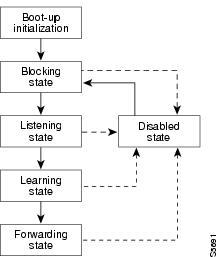
When you enable spanning tree, every port in the switch, VLAN, or network goes through the blocking state and the transitory states of listening and learning at power up. If properly configured, each Layer 2 interface stabilizes to the forwarding or blocking state.
When the spanning tree algorithm places a Layer 2 interface in the forwarding state, the following process occurs:
1.
2.
3.
4.
Blocking State
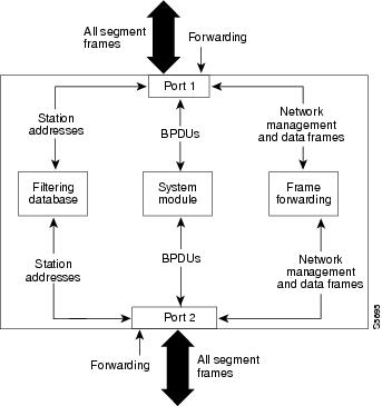
A Layer 2 interface in the blocking state does not participate in frame forwarding, as shown in Figure 2. After initialization, a BPDU is sent out to each Layer 2 interface in the switch. A switch initially assumes it is the root until it exchanges BPDUs with other switches. This exchange establishes which switch in the network is the root or root bridge. If only one switch is in the network, no exchange occurs, the forward delay timer expires, and the ports move to the listening state. A port always enters the blocking state following switch initialization.
Figure 2 Interface 2 in Blocking State
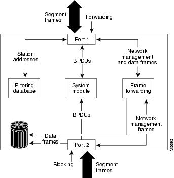
A Layer 2 interface in the blocking state performs as follows:
•
•
•
•
•
•
Listening State
The listening state is the first transitional state a Layer 2 interface enters after the blocking state. The Layer 2 interface enters this state when STP determines that the Layer 2 interface should participate in frame forwarding. Figure 3 shows a Layer 2 interface in the listening state.
Figure 3 Interface 2 in Listening State
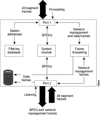
A Layer 2 interface in the listening state performs as follows:
•
•
•
•
•
•
Learning State
A Layer 2 interface in the learning state prepares to participate in frame forwarding. The Layer 2 interface enters the learning state from the listening state. Figure 4 shows a Layer 2 interface in the learning state.
Figure 4 Interface 2 in Learning State
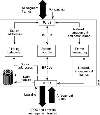
A Layer 2 interface in the learning state performs as follows:
•
•
•
•
•
•
Forwarding State
A Layer 2 interface in the forwarding state forwards frames, as shown in Figure 5. The Layer 2 interface enters the forwarding state from the learning state.
Figure 5 Interface 2 in Forwarding State
A Layer 2 interface in the forwarding state performs as follows:
•
•
•
•
•
•
Disabled State
A Layer 2 interface in the disabled state does not participate in frame forwarding or spanning tree, as shown in Figure 6. A Layer 2 interface in the disabled state is virtually nonoperational.
Figure 6 Interface 2 in Disabled State
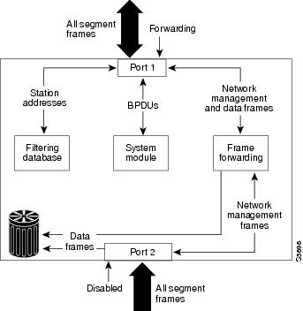
A disabled Layer 2 interface performs as follows:
•
•
•
•
•
MAC Address Allocation
The mac address allocation manager has a pool of MAC addresses that are used as the bridge IDs for the VLAN spanning trees.
MAC addresses are allocated sequentially, with the first MAC address in the range assigned to VLAN 1, the second MAC address in the range assigned to VLAN 2, and so forth.
For example, if the MAC address range is 00-e0-1e-9b-2e-00 to 00-e0-1e-9b-31-ff, the VLAN 1 bridge ID is 00-e0-1e-9b-2e-00, the VLAN 2 bridge ID is 00-e0-1e-9b-2e-01, the VLAN 3 bridge ID is 00-e0-1e-9b-2e-02, and so forth.
Default Spanning Tree Configuration
Spanning Tree Default Configuration
Spanning Tree Port Priority
In the event of a loop, spanning tree considers port priority when selecting an interface to put into the forwarding state. You can assign higher priority values to interfaces that you want spanning tree to select first, and lower priority values to interfaces that you want spanning tree to select last. If all interfaces have the same priority value, spanning tree puts the interface with the lowest interface number in the forwarding state and blocks other interfaces. The possible priority range is 0 through 255, configurable in increments of 4 (the default is 128).
Cisco IOS software uses the port priority value when the interface is configured as an access port and uses VLAN port priority values when the interface is configured as a trunk port.
Spanning Tree Port Cost
The spanning tree port path cost default value is derived from the media speed of an interface. In the event of a loop, spanning tree considers port cost when selecting an interface to put into the forwarding state. You can assign lower cost values to interfaces that you want spanning tree to select first and higher cost values to interfaces that you want spanning tree to select last. If all interfaces have the same cost value, spanning tree puts the interface with the lowest interface number in the forwarding state and blocks other interfaces.
The possible cost range is 0 through 65535 (the default is media-specific).
Spanning tree uses the port cost value when the interface is configured as an access port and uses VLAN port cost values when the interface is configured as a trunk port.
Cisco Discovery Protocol
Cisco Discovery Protocol (CDP) is a protocol that runs over Layer 2 (the data link layer) on all Cisco routers, bridges, access servers, and switches. CDP allows network management applications to discover Cisco devices that are neighbors of already known devices, in particular, neighbors running lower-layer, transparent protocols. With CDP, network management applications can learn the device type and the SNMP agent address of neighboring devices. This feature enables applications to send SNMP queries to neighboring devices.
CDP runs on all LAN and WAN media that support Subnetwork Access Protocol (SNAP). Each CDP-configured device sends periodic messages to a multicast address. Each device advertises at least one address at which it can receive SNMP messages. The advertisements also contain the time-to-live, or hold-time information, which indicates the length of time a receiving device should hold CDP information before discarding it.
Switched Port Analyzer (SPAN)
Switched Port Analyzer (SPAN) Session
A Switched Port Analyzer (SPAN) session is an association of a destination interface with a set of source interfaces. You configure SPAN sessions using parameters that specify the type of network traffic to monitor. SPAN sessions allow you to monitor traffic on one or more interfaces and to send either ingress traffic, egress traffic, or both to one destination interface. You can configure one SPAN session with separate or overlapping sets of SPAN source interfaces or VLANs. Only switched interfaces can be configured as SPAN sources or destinations on the same network module.
SPAN sessions do not interfere with the normal operation of the switch. You can enable or disable SPAN sessions with command-line interface (CLI) or SNMP commands. When enabled, a SPAN session might become active or inactive based on various events or actions, and this would be indicated by a syslog message. The show monitor session SPAN session number command displays the operational status of a SPAN session.
A SPAN session remains inactive after system power-up until the destination interface is operational.
Destination Interface
A destination interface (also called a monitor interface) is a switched interface to which SPAN sends packets for analysis. You can have one SPAN destination interface. Once an interface becomes an active destination interface, incoming traffic is disabled. You cannot configure a SPAN destination interface to receive ingress traffic. The interface does not forward any traffic except that required for the SPAN session.
An interface configured as a destination interface cannot be configured as a source interface. EtherChannel interfaces cannot be SPAN destination interfaces.
Specifying a trunk interface as a SPAN destination interface stops trunking on the interface.
Source Interface
A source interface is an interface monitored for network traffic analysis. One or more source interfaces can be monitored in a single SPAN session with user-specified traffic types (ingress, egress, or both) applicable for all the source interfaces.
You can configure source interfaces in any VLAN. You can configure EtherChannel as source interfaces, which means that all interfaces in the specified VLANs are source interfaces for the SPAN session.
Trunk interfaces can be configured as source interfaces and mixed with nontrunk source interfaces; however, the destination interface never encapsulates.
Traffic Types
Ingress SPAN (Rx) copies network traffic received by the source interfaces for analysis at the destination interface. Egress SPAN (Tx) copies network traffic transmitted from the source interfaces. Specifying the configuration option both copies network traffic received and transmitted by the source interfaces to the destination interface.
SPAN Traffic
Network traffic, including multicast, can be monitored using SPAN. Multicast packet monitoring is enabled by default. In some SPAN configurations, multiple copies of the same source packet are sent to the SPAN destination interface. For example, a bidirectional (both ingress and egress) SPAN session is configured for sources a1 and a2 to a destination interface d1. If a packet enters the switch through a1 and gets switched to a2, both incoming and outgoing packets are sent to destination interface d1; both packets would be the same (unless a Layer-3 rewrite had occurred, in which case the packets would be different).
Note
SPAN Configuration Guidelines and Restrictions
Follow these guidelines and restrictions when configuring SPAN:
•
•
•
•
•
•
•
•
•
•
•
•
•
Quality of Service
Understanding Quality of Service (QoS)
Typically, networks operate on a best-effort delivery basis, which means that all traffic has equal priority and an equal chance of being delivered in a timely manner. When congestion occurs, all traffic has an equal chance of being dropped.
With the QoS feature configured on your switch, you can select specific network traffic, prioritize it according to its relative importance, and use congestion-management and congestion-avoidance techniques to provide preferential treatment. Implementing QoS in your network makes network performance more predictable and bandwidth utilization more effective.
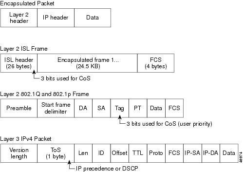
The QoS implementation for this release is based on the DiffServ architecture, an emerging standard from the Internet Engineering Task Force (IETF). This architecture specifies that each packet is classified upon entry into the network. The classification is carried in the IP packet header, using 6 bits from the deprecated IP type of service (ToS) field to carry the classification (class) information. Classification can also be carried in the Layer 2 frame. These special bits in the Layer 2 frame or a Layer 3 packet are described here and shown in Figure 7:
•
Layer 2 802.1Q frame headers have a 2-byte Tag Control Information field that carries the CoS value in the three most-significant bits, which are called the User Priority bits. On interfaces configured as Layer 2 802.1Q trunks, all traffic is in 802.1Q frames except for traffic in the native VLAN.
Other frame types cannot carry Layer 2 CoS values.
Layer 2 CoS values range from 0 for low priority to 7 for high priority.
•
Layer 3 IP packets can carry either an IP precedence value or a Differentiated Services Code Point (DSCP) value. QoS supports the use of either value, because DSCP values are backward-compatible with IP precedence values.
IP precedence values range from 0 to 7.
DSCP values range from 0 to 63.
Figure 7 QoS Classification Layers in Frames and Packets
Note
All switches and routers across the Internet rely on the class information to provide the same forwarding treatment to packets with the same class information and different treatment to packets with different class information. The class information in the packet can be assigned by end hosts or by switches or routers along the way, based on a configured policy, detailed examination of the packet, or both. Detailed examination of the packet is expected to happen closer to the edge of the network so that the core switches and routers are not overloaded.
Switches and routers along the path can use the class information to limit the amount of resources allocated per traffic class. The behavior of an individual device when handling traffic in the DiffServ architecture is called per-hop behavior. If all devices along a path provide a consistent per-hop behavior, you can construct an end-to-end QoS solution.
Implementing QoS in your network can be a simple or complex task and depends on the QoS features offered by your internetworking devices, the traffic types and patterns in your network, and the granularity of control you need over incoming and outgoing traffic.
The Ethernet switch network module can function as a Layer 2 switch connected to a Layer 3 router. When a packet enters the Layer 2 engine directly from a switch port, it is placed into one of four queues in the dynamic, 32-MB shared memory buffer. The queue assignment is based on the dot1p value in the packet. Any voice bearer packets that come in from the Cisco IP phones on the voice VLAN are automatically placed in the highest priority (Queue 3) based on the 802.1p value generated by the IP phone. The queues are then serviced on a WRR basis. The control traffic, which uses a CoS or ToS of 3, is placed in Queue 2.
Table 2 summarizes the queues, CoS values, and weights for Layer 2 QoS on the Ethernet switch network module network module.
Table 2 Queues, CoS values, and Weights for Layer 2 QoS
The weights specify the number of packets that are serviced in the queue before moving on to the next queue. Voice Realtime Transport Protocol (RTP) bearer traffic marked with a CoS or ToS of 5 and Voice Control plane traffic marked with a CoS/ToS of 3 are placed into the highest priority Queues. If the queue has no packets to be serviced, it is skipped. Weighted Random Early Detection (WRED) is not supported on the Fast Ethernet ports.
The WRR default values cannot be changed. There are currently no CLI commands to determine QoS information for WRR weights and queue mappings. You cannot configure port based QoS on the Layer 2 switch ports.
Maximum Number of VLAN and Multicast Groups
The maximum number is less than or equal to 242. The number of VLANs is determined by multiplying the number of VLANs by the number of multicast groups. For example, the maximum number for 10 VLAN's and 20 groups would be 200, under the 242 limit.
IP Multicast Support
The maximum number of multicast groups is related to the maximum number of VLANs. The product of the number of multicast groups and the number of VLANs cannot exceed 242.
•
IGMP snooping Versions 1 and 2
Understanding IGMP Snooping
In VLANs or subnets where you have configured IGMP support by enabling multicast routing on the Router and enabling PIM on the VLAN interfaces IGMP snooping manages multicast traffic at Layer2 dynamically forwarding multicast traffic only to those interfaces that want to receive it.
IGMP snooping constrains traffic in MAC multicast groups 01-00-5e-00-00-01 to 01-00-5e-ff-ff-ff. IGMP snooping does not constrain Layer 2 multicasts generated by routing protocols.
Note
IGMP (on a router) sends out periodic general IGMP queries. When you enable IGMP snooping, the switch responds at Layer 2 to the IGMP queries with only one IGMP join request per Layer 2 multicast group. The switch creates one entry per subnet in the Layer 2 forwarding table for each Layer 2 multicast group from which it receives an IGMP join request. All hosts interested in this multicast traffic send IGMP join requests and are added to the forwarding table entry.
Layer 2 multicast groups learned through IGMP snooping are dynamic.
When a host connected to a Layer 2 interface wants to join an IP multicast group, it sends an IGMP join request specifying the IP multicast group it wants to join. When hosts want to leave a multicast group, they can either ignore the periodic general IGMP queries, or they can send an IGMP leave message. When the switch receives an IGMP leave message from a host, it sends out a group-specific IGMP query to determine if any devices connected to that interface are interested in traffic for the specific multicast group. The switch then updates the table entry for that Layer 2 multicast group so that only those hosts interested in receiving multicast traffic for the group are listed. IGMP Snooping is enabled on a switchport only when the SVI is configured for PIM. IGMP snooping is disabled by default.
Fast-Leave Processing
IGMP snooping fast-leave processing allows the switch to remove an interface from the forwarding-table entry without first sending out group specific queries to the interface. The VLAN interface is pruned from the multicast tree for the multicast group specified in the original leave message. Fast-leave processing ensures optimal bandwidth management for all hosts on a switched network, even when multiple multicast groups are in use simultaneously.
When a switch with IGMP snooping enabled receives an IP group-specific IGMPv2 leave message, it sends a group-specific query out the interface where the leave message was received to determine if there are any other hosts attached to that interface that are interested in the MAC multicast group. If the switch does not receive an IGMP join message within the query-response-interval and none of the other 31 IP groups corresponding to the MAC group are interested in the multicast traffic for that MAC group and no multicast routers have been learned on the interface, then the interface is removed from the portmask of the (mac-group, vlan) entry in the L2 forwarding table. With fast-leave enabled on the VLAN, an interface can be removed immediately from the portmask of the L2 entry when the IGMP leave message is received, unless a multicast router was learned on the port
Note
Storm-Control
Understanding Storm-Control
Storm-control prevents switchports on a LAN from being disrupted by a broadcast, multicast, or unicast storm on one of the interfaces. A LAN storm occurs when packets flood the LAN, creating excessive traffic and degrading network performance. Errors in the protocol-stack implementation or in the network configuration can cause a storm.
Storm-control monitors incoming traffic statistics over a time period and compares the measurement with a predefined suppression level threshold. The threshold represents the percentage of the total available bandwidth of the port. If the threshold of a traffic type is reached, further traffic of that type is suppressed until the incoming traffic falls below the threshold level. Storm-control is disabled by default.
The switch supports storm-control for broadcast, multicast, and unicast traffic. This example of broadcast suppression can also be applied to multicast and unicast traffic.
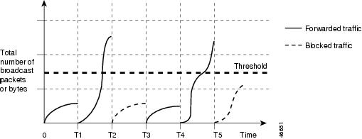
The graph in Figure 8 shows broadcast traffic patterns on an interface over a given period of time. In this example, the broadcast traffic exceeded the configured threshold between time intervals T1 and T2 and between T4 and T5. When the amount of specified traffic exceeds the threshold, all traffic of that kind is dropped. Therefore, broadcast traffic is blocked during those intervals. At the next time interval, if broadcast traffic does not exceed the threshold, it is again forwarded.
Figure 8 Broadcast Suppression Example
When storm-control is enabled, the switch monitors packets passing from an interface to the switching bus and determines if the packet is unicast, multicast, or broadcast. The switch monitors the number of broadcast, multicast, or unicast packets received within the 1-second time interval, and when a threshold for one type of traffic is reached, that type of traffic is dropped. This threshold is specified as a percentage of total available bandwidth that can be used by broadcast (multicast or unicast) traffic.
The combination of broadcast suppression threshold numbers and the 1-second time interval control the way the suppression algorithm works. A higher threshold allows more packets to pass through. A threshold value of 100 percent means that no limit is placed on the traffic.
Note
The switch continues to monitor traffic on the port, and when the utilization level is below the threshold level, the type of traffic that was dropped is forwarded again.
You use the storm-control broadcast, storm-control multicast, and storm-control unicast interface configuration commands to set up the storm-control threshold value.
Port Security
You can use port security to block input to an Ethernet, Fast Ethernet, or Gigabit Ethernet port when the MAC address of the station attempting to access the port is different from any of the MAC addresses specified for that port. Alternatively, you can use port security to filter traffic destined to or received from a specific host based on the host MAC address.
Ethernet Switching in Cisco AVVID Architecture
This section describes the Ethernet switching capabilities of the Ethernet switch network module, which is designed to work as part of the Cisco Architecture for Voice, Video, and Integrated Data (AVVID) solution.
The section outlines how to configure ethernet ports on the Ethernet switch network module to support Cisco IP phones in a branch office on your network. Also included is a section on performing basic tasks on the Ethernet switch network module.
The following topics are included:
•
Configuring the Ethernet switch network module for Cisco AVVID/IP Telephony
The Ethernet switch network module has sixteen 10/100 switched Ethernet ports with integrated inline power and QoS features that make it an ideal choice for extending Cisco AVVID (Architecture for Voice, Video and Integrated Data) based voice-over-IP (VoIP) networks to small branch offices.
As an access gateway switch, the Ethernet switch network module can be deployed as a component of a centralized call-processing network using a centrally deployed Cisco CallManager (CCM). Instead of deploying and managing key systems or PBXs in small branch offices, applications are centrally located at the corporate headquarters or data center and are accessed via the IP WAN.
Default Switch Configuration
By default, the Ethernet switch network module provides the following settings with respect to Cisco AVVID:
•
•
•
•
Stacking
Multiple switch modules may be installed simultaneously by connecting the Gigabit Ethernet (GE) ports of the Cisco EtherSwitch network module. This connection sustains a line-rate traffic similar to the switch fabric found in Cisco Catalyst switches and forms a single VLAN consisting of all ports in multiple Cisco EtherSwitch network modules. The stacking port must be configured for multiple switch modules to operate correctly in the same chassis.
•
•
For more details about the requirements for installing and connecting Cisco EtherSwitch network modules in a single chassis, go to the following URL:
Flow Control
Flow-control is a feature that Gigabit Ethernet ports use to inhibit the transmission of incoming packets. If a buffer on a Gigabit Ethernet port runs out of space, the port transmits a special packet that requests remote ports to delay sending packets for a period of time. This special packet is called a pause frame.
Using Flow-Control Keywords
Table 3 describes guidelines for using different configurations of the send and receive keywords with the set port flowcontrol command.
Benefits
•
•
•
•
•
•
Interface Range Specification feature makes configuration easier because:
•
•
Restrictions
The following features are not supported in this release:
•
•
•
•
•
•
•
•
•
•
•
•
•
•
•
•
•
•
Related Features and Technologies
•
•
•
Related Documents
For information about installing voice network modules and voice interface cards in Cisco 2600 series, Cisco 3600 series, and Cisco 3700 series routers see these publications:
•
•
•
•
•
•
•
For information about configuring Voice over IP features, see these publications:
•
•
•
For more information on Flow control, see the following publication:
•
Supported Platforms
•
•
•
Determining Platform Support Through Cisco Feature Navigator
Cisco IOS software is packaged in feature sets that support specific platforms. To get updated information regarding platform support for this feature, access Cisco Feature Navigator. Cisco Feature Navigator dynamically updates the list of supported platforms as new platform support is added for the feature.
Cisco Feature Navigator is a web-based tool that enables you to determine which Cisco IOS software images support a specific set of features and which features are supported in a specific Cisco IOS image. You can search by feature or release. Under the release section, you can compare releases side by side to display both the features unique to each software release and the features in common.
To access Cisco Feature Navigator, you must have an account on Cisco.com. If you have forgotten or lost your account information, send a blank e-mail to cco-locksmith@cisco.com. An automatic check will verify that your e-mail address is registered with Cisco.com. If the check is successful, account details with a new random password will be e-mailed to you. Qualified users can establish an account on Cisco.com by following the directions at http://www.cisco.com/register.
Cisco Feature Navigator is updated regularly when major Cisco IOS software releases and technology releases occur. For the most current information, go to the Cisco Feature Navigator home page at the following URL:
Availability of Cisco IOS Software Images
Platform support for particular Cisco IOS software releases is dependent on the availability of the software images for those platforms. Software images for some platforms may be deferred, delayed, or changed without prior notice. For updated information about platform support and availability of software images for each Cisco IOS software release, refer to the online release notes or, if supported, Cisco Feature Navigator.
Supported Standards, MIBs, and RFCs
Standards
•
•
•
MIBs
•
•
•
•
•
•
•
•
•
•
•
•
•
•
•
•
•
•
•
•
•
•
•
•
•
•
•
To obtain lists of supported MIBs by platform and Cisco IOS release, and to download MIB modules, go to the Cisco MIB website on Cisco.com at the following URL:
http://www.cisco.com/public/sw-center/netmgmt/cmtk/mibs.shtml
RFCs
No new or modified RFCs are supported by this feature.s
Prerequisites
•
•
In addition, complete the following tasks before configuring this feature:
•
For more information on IP routing, refer to the Cisco IOS IP Configuration Guide, Release 12.2.
•
For more information on setting up call agents, refer to the documentation that accompanies the call agents used in your network configuration.
Configuration Tasks
See the following sections for configuration tasks for the Ethernet switch network module.
•
•
•
•
•
•
•
•
•
•
•
Configuring Layer 2 Interfaces
•
•
•
•
•
Configuring a Range of Interfaces
To configure a range of interfaces, use the interface range command in global configuration mode:
Defining a Range Macro
Verifying Configuration of a Range of Interfaces
Step 1
Router#show running-configuration | include define define interface-range enet_list FastEthernet5/1 - 4
Configuring Layer 2 Optional Interface Features
•
•
•
•
•
•
Interface Speed and Duplex Configuration Guidelines
When configuring an interface speed and duplex mode, note these guidelines:
•
•
•

Caution
Configuring the Interface Speed
Note
Configuring the Interface Duplex Mode
To set the duplex mode of an Ethernet or Fast Ethernet interface, use the following commands beginning in global configuration mode:
Note
Router(config)# interface fastethernet 5/4Router(config-if)# duplex fullVerifying Interface Speed and Duplex Mode Configuration
Step 1
Router# show interfaces fastethernet 1/4
FastEthernet1/4 is up, line protocol is down
Hardware is Fast Ethernet, address is 0000.0000.0c89 (bia 0000.0000.0c89)
MTU 1500 bytes, BW 100000 Kbit, DLY 100 usec,
reliability 255/255, txload 1/255, rxload 1/255
Encapsulation ARPA, loopback not set
Keepalive set (10 sec)
Auto-duplex, Auto-speed
ARP type: ARPA, ARP Timeout 04:00:00
Last input never, output never, output hang never
Last clearing of "show interface" counters never
Queueing strategy: fifo
Output queue 0/40, 0 drops; input queue 0/75, 0 drops
5 minute input rate 0 bits/sec, 0 packets/sec
5 minute output rate 0 bits/sec, 0 packets/sec
0 packets input, 0 bytes, 0 no buffer
Received 0 broadcasts, 0 runts, 0 giants, 0 throttles
0 input errors, 0 CRC, 0 frame, 0 overrun, 0 ignored
0 input packets with dribble condition detected
3 packets output, 1074 bytes, 0 underruns(0/0/0)
0 output errors, 0 collisions, 5 interface resets
0 babbles, 0 late collision, 0 deferred
0 lost carrier, 0 no carrier0 output buffer failures, 0 output buffers swapped outRouter#
Configuring a Description for an Interface
You can add a description about an interface to help you remember its function. The description appears in the output of the following commands: show configuration, show running-config, and show interfaces.
To add a description for an interface, use the description command in interface configuration mode:
Configuring an Ethernet Interface as a Layer 2 Trunk
To configure an Ethernet interface as a Layer 2 trunk, use the following commands, beginning in global configuration mode:
Note
Verifying an Ethernet Interface as a Layer 2 Trunk
Step 1
Router# show running-config interface fastethernet 5/8Building configuration...Current configuration:!interface FastEthernet5/8no ip addressswitchportswitchport trunk encapsulation dot1qendStep 2
Router#show interfaces fastethernet 5/8 switchportName: Fa5/8Switchport: EnabledAdministrative Mode: static accessOperational Mode: static accessAdministrative Trunking Encapsulation: dot1qOperational Trunking Encapsulation: nativeNegotiation of Trunking: DisabledAccess Mode VLAN: 1 (default)Trunking Native Mode VLAN: 1 (default)Trunking VLANs Enabled: ALLPruning VLANs Enabled: 2-1001Protected: falseUnknown unicast blocked: falseUnknown multicast blocked: falseBroadcast Suppression Level: 100Multicast Suppression Level: 100Unicast Suppression Level: 100Voice VLAN: noneAppliance trust: noneStep 3
Router#show interfaces fastethernet 5/8 trunkPort Mode Encapsulation Status Native vlanFa1/15 off 802.1q not-trunking 1Port Vlans allowed on trunkFa1/15 1Port Vlans allowed and active in management domainFa1/15 1Port Vlans in spanning tree forwarding state and not prunedFa1/15 1
Configuring an Ethernet Interface as a Layer 2 Access
To configure an Ethernet Interface as a Layer 2 access use the following commands, beginning in global configuration mode:
Verifying an Ethernet Interface as a Layer 2 Access
Step 1
Router#show running-config interface {ethernet | fastethernet} slot/port
Step 1
Router#show interfaces [ethernet | fastethernet] slot/port switchport
Configuring VLANs
This section describes how to configure the VLANs on the Ethernet switch network modules, and contains the following sections:
•
•
Configuring VLANs
To configure an Ethernet Interface as a Layer 2 access, use the following commands beginning in EXEC mode:
Verifying the VLAN Configuration.
Step 1
Router# show vlan name VLAN0003VLAN Name Status Ports---- -------------------------------- --------- -------------------------------1 default active Fa1/0, Fa1/1, Fa1/2, Fa1/3Fa1/4, Fa1/5, Fa1/6, Fa1/7Fa1/8, Fa1/9, Fa1/10, Fa1/11Fa1/12, Fa1/13, Fa1/14, Fa1/151002 fddi-default active1003 token-ring-default active1004 fddinet-default active1005 trnet-default activeVLAN Type SAID MTU Parent RingNo BridgeNo Stp BrdgMode Trans1 Trans2---- ----- ---------- ----- ------ ------ -------- ---- -------- ------ ------1 enet 100001 1500 - - - - - 1002 10031002 fddi 101002 1500 - - - - - 1 10031003 tr 101003 1500 1005 0 - - srb 1 10021004 fdnet 101004 1500 - - 1 ibm - 0 01005 trnet 101005 1500 - - 1 ibm - 0 0Router#
Deleting a VLAN from the Database
Step 1
Enters VLAN configuration mode.
Step 2
Step 3
Router(vlan)# exit
Verifying VLAN Deletion
Step 1
Router#show vlan-switch briefVLAN Name Status Ports---- -------------------------------- --------- -------------------------------1 default active Fa0/2, Fa0/9, Fa0/14, Gi0/02 VLAN0002 active3 VLAN0003 active Fa0/4, Fa0/5, Fa0/10, Fa0/114 VLAN0004 active Fa0/6, Fa0/7, Fa0/12, Fa0/135 VLAN0005 active40 VLAN0040 active Fa0/1550 VLAN0050 active1000 VLAN1000 active1002 fddi-default active1003 token-ring-default active1004 fddinet-default active1005 trnet-default activeRouter#
Configuring VLAN Trunking Protocol (VTP)
This section describes how to configure the VLAN Trunking Protocol (VTP) on the Ethernet switch network module, and contains the following sections:
•
Configuring VTP Server
When a switch is in VTP server mode, you can change the VLAN configuration and have it propagate throughout the network.
To configure the switch as a VTP server, use the following commands beginning in privileged EXEC mode:
Configuring a VTP Client
When a switch is in VTP client mode, you cannot change the VLAN configuration on the switch. The client switch receives VTP updates from a VTP server in the management domain and modifies its configuration accordingly.
Disabling VTP (VTP Transparent Mode)
When you configure the switch as VTP transparent, you disable VTP on the switch. A VTP transparent switch does not send VTP updates and does not act on VTP updates received from other switches. However, a VTP transparent switch running VTP version 2 does forward received VTP advertisements out all of its trunk links.
To disable VTP on the switch, use the following commands beginning in privileged EXEC mode:
Configuring VTP version 2
To enable VTP version 2, use the following commands beginning in privileged EXEC mode:
Step 1
Router# vlan databaseStep 2
Enables VTP version 2. Use the no keyword to disable VTP version 2.
Step 3
Router(vlan)# exit
Verifying VTP
Step 1
Router# show vtp statusVTP Version : 2Configuration Revision : 247Maximum VLANs supported locally : 1005Number of existing VLANs : 33VTP Operating Mode : ClientVTP Domain Name : Lab_NetworkVTP Pruning Mode : EnabledVTP V2 Mode : DisabledVTP Traps Generation : DisabledMD5 digest : 0x45 0x52 0xB6 0xFD 0x63 0xC8 0x49 0x80Configuration last modified by 0.0.0.0 at 8-12-99 15:04:49Router#
Configuring Layer 2 EtherChannels (Port-Channel Logical Interfaces)
•
•
•
•
Configuring Layer 2 EtherChannels (Port-Channel Logical Interfaces)
To configure Layer 2 EtherChannels, configure the Ethernet interfaces with the channel-group command, which creates the port-channel logical interface.
Note
Note
To configure Layer 2 Ethernet interfaces as a Layer 2 EtherChannel, use the following commands beginning in global configuration mode for each interface:
Verifying Layer 2 EtherChannels
Use the following show commands to verify Layer 2 EtherChannels, as illustrated below:
Step 1
Router#show running-config interface fastethernet 5/6Building configuration...Current configuration:!interface FastEthernet5/6no ip addressswitchportswitchport access vlan 10switchport mode accesschannel-group 2 mode onendStep 2
Router#show interfaces fastethernet 5/6 etherchannelPort state = EC-Enbld Up In-Bndl Usr-ConfigChannel group = 2 Mode = Desirable Gcchange = 0Port-channel = Po2 GC = 0x00020001Port indx = 1 Load = 0x55Flags: S - Device is sending Slow hello. C - Device is in Consistent state.A - Device is in Auto mode. P - Device learns on physical port.Timers: H - Hello timer is running. Q - Quit timer is running.S - Switching timer is running. I - Interface timer is running.Local information:Hello Partner PAgP Learning GroupPort Flags State Timers Interval Count Priority Method IfindexFa5/6 SC U6/S7 30s 1 128 Any 56Partner's information:Partner Partner Partner Partner GroupPort Name Device ID Port Age Flags Cap.Fa5/6 JAB031301 0050.0f10.230c 2/47 18s SAC 2FAge of the port in the current state: 00h:10m:57sStep 3
Router#show running-config interface port-channel 2Building configuration...Current configuration:!interface Port-channel2no ip addressswitchportswitchport access vlan 10switchport mode accessendRouter#Step 4
Router#show etherchannel 2 port-channelPort-channels in the group:----------------------Port-channel: Po2------------Age of the Port-channel = 00h:23m:33sLogical slot/port = 10/2 Number of ports in agport = 2GC = 0x00020001 HotStandBy port = nullPort state = Port-channel Ag-InusePorts in the Port-channel:Index Load Port-------------------1 55 Fa5/60 AA Fa5/7Time since last port bundled: 00h:23m:33s Fa5/6
Configuring EtherChannel Load Balancing
To configure EtherChannel load balancing, use the following command in global configuration mode:
Note
Verifying EtherChannel Load Balancing
Step 1
Router# show etherchannel load-balanceSource XOR Destination IP addressRouter#
Removing an Interface from an EtherChannel
To remove an Ethernet interface from an EtherChannel, use the following commands in global configuration mode:
Configuring Removing an EtherChannel
To remove an EtherChannel, use the following command in global configuration mode:
Step 1
Removes the port-channel interface.
Step 2
Router(config)# endExits configuration mode.
Verify Removing an EtherChannel
Step 1
Router#show etherchannel summaryFlags: D - down P - in port-channelI - stand-alone s - suspendedR - Layer3 S - Layer2U - in useGroup Port-channel Ports-----+------------+-----------------------------------------------------------Router#
Configuring Spanning Tree
•
•
•
•
•
Enabling Spanning Tree
You can enable spanning tree on a per-VLAN basis. The switch maintains a separate instance of spanning tree for each VLAN (except on VLANs on which you disable spanning tree).
Step 1
Step 2
Router(config)# endExits configuration mode.
Verify Spanning Tree
Step 1
Router# show spanning-tree vlan 200VLAN200 is executing the ieee compatible Spanning Tree protocolBridge Identifier has priority 32768, address 0050.3e8d.6401Configured hello time 2, max age 20, forward delay 15Current root has priority 16384, address 0060.704c.7000Root port is 264 (FastEthernet5/8), cost of root path is 38Topology change flag not set, detected flag not setNumber of topology changes 0 last change occurred 01:53:48 agoTimes: hold 1, topology change 24, notification 2hello 2, max age 14, forward delay 10Timers: hello 0, topology change 0, notification 0Port 264 (FastEthernet5/8) of VLAN200 is forwardingPort path cost 19, Port priority 128, Port Identifier 129.9.Designated root has priority 16384, address 0060.704c.7000Designated bridge has priority 32768, address 00e0.4fac.b000Designated port id is 128.2, designated path cost 19Timers: message age 3, forward delay 0, hold 0Number of transitions to forwarding state: 1BPDU: sent 3, received 3417Router#
Configuring Spanning Tree Port Priority
To configure the spanning tree port priority of an interface, use the following commands beginning in global configuration mode:
Verify Spanning Tree Port Priority
Step 1
Router# show spanning-tree interface fastethernet 5/8Port 264 (FastEthernet5/8) of VLAN200 is forwardingPort path cost 19, Port priority 100, Port Identifier 129.8.Designated root has priority 32768, address 0010.0d40.34c7Designated bridge has priority 32768, address 0010.0d40.34c7Designated port id is 128.1, designated path cost 0Timers: message age 2, forward delay 0, hold 0Number of transitions to forwarding state: 1BPDU: sent 0, received 13513Router#
Configuring Spanning Tree Port Cost
To configure the spanning tree port cost of an interface, use the following commands beginning in global configuration mode:
Verifying Spanning Tree Port Cost
Step 1
Router# show spanning-tree vlan 200!!!Port 264 (FastEthernet5/8) of VLAN200 is forwardingPort path cost 17, Port priority 64, Port Identifier 129.8.Designated root has priority 32768, address 0010.0d40.34c7Designated bridge has priority 32768, address 0010.0d40.34c7Designated port id is 128.1, designated path cost 0Timers: message age 2, forward delay 0, hold 0Number of transitions to forwarding state: 1BPDU: sent 0, received 13513!!!Router#
Configuring the Bridge Priority of a VLAN
Caution
To configure the spanning tree bridge priority of a VLAN, use the following command in global configuration mode:
Verifying the Bridge Priority of a VLAN
Step 1
Router# show spanning-tree vlan 200 bridge briefHello Max FwdVlan Bridge ID Time Age Delay Protocol---------------- -------------------- ---- ---- ----- --------VLAN200 33792 0050.3e8d.64c8 2 20 15 ieeeRouter#
Configuring the Hello Time
To configure the hello interval for the spanning tree, use the following command in global configuration mode:
Configuring the Forward-Delay Time for a VLAN
Configuring the Maximum Aging Time for a VLAN
To configure the maximum age interval for the spanning tree, use the following command in global configuration mode:
Configuring the Root Bridge
The Ethernet switch network module maintains a separate instance of spanning tree for each active VLAN configured on the switch. A bridge ID, consisting of the bridge priority and the bridge MAC address, is associated with each instance. For each VLAN, the switch with the lowest bridge ID will become the root bridge for that VLAN.
To configure a VLAN instance to become the root bridge, the bridge priority can be modified from the default value (32768) to a significantly lower value so that the bridge becomes the root bridge for the specified VLAN. Use the spanning-tree vlan vlan-ID root command to alter the bridge priority.
The switch checks the bridge priority of the current root bridges for each VLAN. The bridge priority for the specified VLANs is set to 8192 if this value will cause the switch to become the root for the specified VLANs.
If any root switch for the specified VLANs has a bridge priority lower than 8192, the switch sets the bridge priority for the specified VLANs to 1 less than the lowest bridge priority.
For example, if all switches in the network have the bridge priority for VLAN 100 set to the default value of 32768, entering the spanning-tree vlan 100 root primary command on a switch will set the bridge priority for VLAN 100 to 8192, causing the switch to become the root bridge for VLAN 100.
Note
Use the diameter keyword to specify the Layer 2 network diameter (that is, the maximum number of bridge hops between any two end stations in the Layer 2 network). When you specify the network diameter, the switch automatically picks an optimal hello time, forward delay time, and maximum age time for a network of that diameter, which can significantly reduce the spanning tree convergence time. You can use the hello keyword to override the automatically calculated hello time.
Note
To configure the switch as the root, use the following command in global configuration mode:
Disabling Spanning Tree
Step 1
Disables spanning tree on a per-VLAN basis.
Step 2
Router(config)# endExits configuration mode.
Verifying that Spanning Tree is Disabled.
Step 1
Router# show spanning-tree vlan 200<...output truncated...>Spanning tree instance for VLAN 200 does not exist.Router#
Configuring Mac Table Manipulation — Port Security
•
•
Enabling Known MAC Address Traffic
To enable the MAC address secure option, use the following commands beginning in privileged EXEC mode:
Verifying the mac-address-table secure
Step 1
Router# show mac-address-table secureSecure Address Table:Destination Address Address Type VLAN Destination Port------------------- ------------ ---- --------------------0003.0003.0003 Secure 1 FastEthernet 2/8
Creating a Static or Dynamic Entry in the MAC Address Table
To create a static or dynamic entry in the mac address table, use the following commands beginning in privileged EXEC mode:
Note
Verifying the mac-address-table
Step 1
Router# show macDestination Address Address Type VLAN Destination Port------------------- ------------ ---- --------------------0001.6443.6440 Static 1 Vlan10004.c16d.9be1 Dynamic 1 FastEthernet2/130004.ddf0.0282 Dynamic 1 FastEthernet2/130006.0006.0006 Dynamic 1 FastEthernet2/13001b.001b.ad45 Dynamic 1 FastEthernet2/13
Configuring aging-timer
To configure the aging-timer, use the following commands beginning in privileged EXEC mode:
Caution
Verifying the aging-timer
Step 1
Router # show mac-address-table aging-timeMac address aging time 23
Configuring Cisco Discovery Protocol (CDP)
•
Configuring Cisco Discovery Protocol (CDP)
Step 1
Enables CDP globally. Use the no keyword to disable CDP.
Verifying the CDP Global Configuration
Step 1
Router# show cdpGlobal CDP information:Sending CDP packets every 120 secondsSending a holdtime value of 180 secondsSending CDPv2 advertisements is enabledRouter#
Enabling CDP on an Interface
To enable CDP on an interface, use the following command in interface configuration mode:
The following example shows how to enable CDP on Fast Ethernet interface 5/1:
Router(config)# interface fastethernet 5/1Router(config-if)# cdp enableVerifying the CDP Interface Configuration
Step 1
Router# show cdp interface fastethernet 5/1FastEthernet5/1 is up, line protocol is upEncapsulation ARPASending CDP packets every 120 secondsHoldtime is 180 secondsRouter#
Verifying CDP Neighbors
Step 1
Router# show cdp neighborsCapability Codes: R - Router, T - Trans Bridge, B - Source Route BridgeS - Switch, H - Host, I - IGMP, r - RepeaterDevice ID Local Intrfce Holdtme Capability Platform Port IDJAB023807H1 Fas 5/3 127 T S WS-C2948 2/46JAB023807H1 Fas 5/2 127 T S WS-C2948 2/45JAB023807H1 Fas 5/1 127 T S WS-C2948 2/44JAB023807H1 Gig 1/2 122 T S WS-C2948 2/50JAB023807H1 Gig 1/1 122 T S WS-C2948 2/49JAB03130104 Fas 5/8 167 T S WS-C4003 2/47JAB03130104 Fas 5/9 152 T S WS-C4003 2/48
Monitoring and Maintaining CDP
Switched Port Analyzer (SPAN)
•
•
•
Configuring Switched Port Analyzer (SPAN)
To configure the source for a SPAN session, use the following command in global configuration mode:
Note
The following example shows how to configure SPAN session 1 to monitor bidirectional traffic from source interface Fast Ethernet 5/1:
Router(config)# monitor session 1 source interface fastethernet 5/1Configuring SPAN Destinations
To configure the destination for a SPAN session, use the following command in global configuration mode:
Removing Sources or Destinations from a SPAN Session
To remove sources or destinations from a SPAN session, use the following command in global configuration mode:
Step 1
Router(config)# no monitor session session_number
Clears existing SPAN configuration for a session.
Configuring Power Management on the Interface
To manage the powering of the Cisco IP phones, use the following commands beginning in privileged EXEC mode:
Verifying Power Management on the Interface
Step 1
Router#show power inlinePowerSupply SlotNum. Maximum Allocated Status----------- -------- ------- --------- ------EXT-PS 1 165.000 20.000 PS1 GOOD PS2 ABSENTInterface Config Phone Powered PowerAllocated--------- ------ ----- ------- --------------FastEthernet1/0 auto no off 0.000 WattsFastEthernet1/1 auto no off 0.000 WattsFastEthernet1/2 auto no off 0.000 WattsFastEthernet1/3 auto no off 0.000 WattsFastEthernet1/4 auto unknown off 0.000 WattsFastEthernet1/5 auto unknown off 0.000 WattsFastEthernet1/6 auto unknown off 0.000 WattsFastEthernet1/7 auto unknown off 0.000 WattsFastEthernet1/8 auto unknown off 0.000 WattsFastEthernet1/9 auto unknown off 0.000 WattsFastEthernet1/10 auto unknown off 0.000 WattsFastEthernet1/11 auto yes on 6.400 WattsFastEthernet1/12 auto yes on 6.400 WattsFastEthernet1/13 auto no off 0.000 WattsFastEthernet1/14 auto unknown off 0.000 WattsFastEthernet1/15 auto unknown off 0.000 Watts
Verifying Other Power Management CLI
Step 1
Router#show power inline [actual | interface fastethernet port/slot | configured]
Configuring IP Multicast Layer 3 Switching
These sections describe how to configure IP multicast Layer 3 switching:
•
•
•
•
Enabling IP Multicast Routing Globally
You must enable IP multicast routing globally before you can enable IP multicast Layer 3 switching on Layer 3 interfaces.
For complete information and procedures, refer to these publications:
•
•
•
•
To enable IP multicast routing globally, Use this command in global configuration mode:
Enabling IP PIM on Layer 3 Interfaces
You must enable PIM on the Layer 3 interfaces before IP multicast Layer 3 switching functions on those interfaces.
To enable IP PIM on a Layer 3 interface, use the following commands beginning in global configuration mode:
This example shows how to enable PIM on an interface using the default mode (sparse-dense-mode):
Router(config-if)# ip pimRouter(config-if)#This example shows how to enable PIM sparse mode on an interface:
Router(config-if)# ip pim sparse-modeRouter(config-if)#Verifying IP Multicast Layer 3 Hardware Switching Summary
Note
The show ip pim interface count command verifies the IP multicast Layer 3 switching enable state on IP PIM interfaces and the number of packets received and sent on the interface.
Use the following show commands to verify IP multicast Layer 3 switching information for an IP PIM Layer 3 interface, as illustrated below:
Step 1
Router#show ip pim interface countState:* - Fast Switched, D - Distributed Fast SwitchedH - Hardware Switching EnabledAddress Interface FS Mpackets In/Out10.15.1.20 GigabitEthernet4/8 * H 952/423713077010.20.1.7 GigabitEthernet4/9 * H 1385673757/3410.25.1.7 GigabitEthernet4/10* H 0/3410.11.1.30 FastEthernet6/26 * H 0/010.37.1.1 FastEthernet6/37 * H 0/01.22.33.44 FastEthernet6/47 * H 514/68Step 2
Router#show ip mroute countIP Multicast Statistics56 routes using 28552 bytes of memory13 groups, 3.30 average sources per groupForwarding Counts:Pkt Count/Pkts per second/Avg Pkt Size/Kilobits per secondOther counts:Total/RPF failed/Other drops(OIF-null, rate-limit etc)Group:224.2.136.89, Source count:1, Group pkt count:29051Source:132.206.72.28/32, Forwarding:29051/-278/1186/0, Other:85724/8/56665Router#
Note
Step 3
Router#show ip interface vlan 10Vlan10 is up, line protocol is upInternet address is 10.0.0.6/8Broadcast address is 255.255.255.255Address determined by non-volatile memoryMTU is 1500 bytesHelper address is not setDirected broadcast forwarding is disabledMulticast reserved groups joined: 224.0.0.1 224.0.0.2 224.0.0.13 224.0.0.10Outgoing access list is not setInbound access list is not setProxy ARP is enabledSecurity level is defaultSplit horizon is enabledICMP redirects are always sentICMP unreachables are never sentICMP mask replies are never sentIP fast switching is enabledIP fast switching on the same interface is disabledIP Flow switching is disabledIP CEF switching is enabledIP Fast switching turbo vectorIP Normal CEF switching turbo vectorIP multicast fast switching is enabledIP multicast distributed fast switching is disabledIP route-cache flags are Fast, CEFRouter Discovery is disabledIP output packet accounting is disabledIP access violation accounting is disabledTCP/IP header compression is disabledRTP/IP header compression is disabledProbe proxy name replies are disabledPolicy routing is disabledNetwork address translation is disabledWCCP Redirect outbound is disabledWCCP Redirect exclude is disabledBGP Policy Mapping is disabledIP multicast multilayer switching is enabledIP mls switching is enabledRouter#Verifying the IP Multicast Routing Table
Step 1
Router# show ip mroute 230.13.13.1IP Multicast Routing TableFlags:D - Dense, S - Sparse, s - SSM Group, C - Connected, L - Local,P - Pruned, R - RP-bit set, F - Register flag, T - SPT-bit set,J - Join SPT, M - MSDP created entry, X - Proxy Join Timer RunningA - Advertised via MSDP, U - URD, I - Received Source Specific HostReportOutgoing interface flags:H - Hardware switchedTimers:Uptime/ExpiresInterface state:Interface, Next-Hop or VCD, State/Mode(*, 230.13.13.1), 00:16:41/00:00:00, RP 10.15.1.20, flags:SJCIncoming interface:GigabitEthernet4/8, RPF nbr 10.15.1.20Outgoing interface list:GigabitEthernet4/9, Forward/Sparse-Dense, 00:16:41/00:00:00, H(*, 230.13.13.2), 00:16:41/00:00:00, RP 10.15.1.20, flags:SJCIncoming interface:GigabitEthernet4/8, RPF nbr 10.15.1.20, RPF-MFDOutgoing interface list:GigabitEthernet4/9, Forward/Sparse-Dense, 00:16:41/00:00:00, H(10.20.1.15, 230.13.13.1), 00:14:31/00:01:40, flags:CJTIncoming interface:GigabitEthernet4/8, RPF nbr 10.15.1.20, RPF-MFDOutgoing interface list:GigabitEthernet4/9, Forward/Sparse-Dense, 00:14:31/00:00:00, H(132.206.72.28, 224.2.136.89), 00:14:31/00:01:40, flags:CJTIncoming interface:GigabitEthernet4/8, RPF nbr 10.15.1.20, RPF-MFDOutgoing interface list:NullRouter#
Note
Configuring IGMP Snooping
Default IGMP Snooping Configuration
IGMP Snooping is enabled by default on a VLAN or subnet basis. Multicast routing has to be enabled on the router first and then PIM (Multicast routing protocol) has to be enabled on the VLAN interface so that the switch acknowledges the IGMP join and leave messages which are sent from the hosts connected to the switch.
Router(config)#ip multicast-routingRouter(config-if)#interface VLAN1ip-address 192.168.10.1 255.255.255.0ip pim sparse-modeTo verify multicasting support:
Router#show ip igmp groupTo verify IGMP snooping:
Router#show mac-address-table multicast igmp-snoopingTo verify the multicast routing table:
Router#show ip mrouteConfiguring Storm-Control
This section describes how to configure storm-control and characteristics on your router and consists of the following configuration information and procedures:
•
Default Storm-Control Configuration
By default, unicast, broadcast, and multicast suppression is disabled on the switch.
Enabling Storm-Control
Enable storm-control globally and enter the percentage of total available bandwidth that you want to be used by a all traffic (multicast, unicast,); entering 100 percent would allow all traffic.
To enable a particular type of storm-control, use the following commands beginning in privileged EXEC mode:
Verifying Storm-Control
Step 1
Router# show storm-controlStep 2
To verify storm-control statistics on an interface, use the following commands beginning in privileged EXEC mode:
The following is sample output from the show interface counters broadcast privileged EXEC command:
Router#show interface counters broadcastPort BcastSuppDiscardsFa0/1 0Fa0/2 0
Configuring Separate Voice and Data VLANs
For ease of network administration and increased scalability, network managers can configure the Ethernet switch network module to support Cisco IP phones such that the voice and data traffic reside on separate VLANs. We recommend configuring separate VLANs when you are able to segment the existing IP address space of your branch office.
User priority bits in the 802.1p portion of the 802.1Q standard header are used to provide prioritization in Ethernet switches. This is a vital component in designing Cisco AVVID networks.
The Ethernet switch network module provides the performance and intelligent services of Cisco IOS Software for branch office applications. The Ethernet switch network module can identify user applications—such as voice or multicast video—and classify traffic with the appropriate priority levels. QoS policies are enforced using Layer 2 and 3 information such as 802.1p, IP precedence, and DSCP.
Note
To automatically configure Cisco IP phones to send voice traffic on the voice VLAN ID (VVID) on a per-port basis (see the "Voice Traffic and VVID" section), use the following commands beginning in global configuration mode:
Voice Traffic and VVID
The Ethernet switch network module can automatically configure voice VLAN. This capability overcomes the management complexity of overlaying a voice topology onto a data network while maintaining the quality of voice traffic. With the automatically configured voice VLAN feature, network administrators can segment phones into separate logical networks, even though the data and voice infrastructure is physically the same. The voice VLAN feature places the phones into their own VLANs without the need for end-user intervention. A user can plug the phone into the switch, and the switch provides the phone with the necessary VLAN information
Configuring a Single Subnet for Voice and Data
For network designs with incremental IP telephony deployment, network managers can configure the Ethernet switch network module so that the voice and data traffic coexist on the same subnet. This might be necessary when it is impractical either to allocate an additional IP subnet for IP phones or to divide the existing IP address space into an additional subnet at the remote branch, it might be necessary to use a single IP address space for branch offices. (This is one of the simpler ways to deploy IP telephony.) When this is the case, you must still prioritize voice above data at both Layer 2 and Layer 3.
Layer 3 classification is already handled because the phone sets the Type of Service (ToS) bits in all media streams to an IP Precedence value of 5. (With Cisco CallManager Release 3.0(5), this marking changed to a Differentiated Services Code Point ([DSCP]) value of EF.) However, to ensure that there is
Layer 2 classification for admission to the multiple queues in the branch office switches, the phone must also use the User Priority bits in the Layer 2 802.1p header to provide Class of Service (CoS) marking. Setting the bits to provide marking can be done by having the switch look for 802.1p headers on the native VLAN.This configuration approach must address two key considerations:
•
•
To automatically configure Cisco IP phones to send voice and data traffic on the same VLAN, use the following commands beginning in privileged EXEC mode:
Verifying Switchport Configuration
Step 1
Router# show run interface <interface>Step 2
Router#write memory
Configuring Ethernet Ports to Support Cisco IP Phones with Multiple Ports
You might want to use multiple ports to connect the Cisco IP phones if any of the following conditions apply to your Cisco IP telephony network:
•
•
•
•
IP Addressing
The recommended configuration for using multiple cables to connect IP phones to the Cisco AVVID network is to use a separate IP subnet and separate VLANs for IP telephony.
Managing the Ethernet switch network module
This section illustrates how to perform basic management tasks on the Ethernet switch network module with the Cisco IOS CLI. You might find this information useful when you configure the switch for the previous scenarios.
The following topics are included:
•
•
Adding Trap Managers
A trap manager is a management station that receives and processes traps. When you configure a trap manager, community strings for each member switch must be unique. If a member switch has an IP address assigned to it, the management station accesses the switch by using its assigned IP address.
By default, no trap manager is defined, and no traps are issued.
To add a trap manager and community string, use the following commands beginning in privileged EXEC mode:
Verifying Trap Managers
Step 1
Router# show running-config
Configuring IP Information
This section describes how to assign IP information on the Ethernet switch network module. The following topics are included:
•
•
Assigning IP Information to the Switch
You can use a BOOTP server to automatically assign IP information to the switch; however, the BOOTP server must be set up in advance with a database of physical MAC addresses and corresponding IP addresses, subnet masks, and default gateway addresses. In addition, the switch must be able to access the BOOTP server through one of its ports. At startup, a switch without an IP address requests the information from the BOOTP server; the requested information is saved in the switch running the configuration file. To ensure that the IP information is saved when the switch is restarted, save the configuration by entering the write memory command in privileged EXEC mode.
You can change the information in these fields. The mask identifies the bits that denote the network number in the IP address. When you use the mask to subnet a network, the mask is then referred to as a subnet mask. The broadcast address is reserved for sending messages to all hosts. The CPU sends traffic to an unknown IP address through the default gateway.
To enter the IP information, use the following commands beginning in privileged EXEC mode:
Use the following procedure to remove the IP information from a switch.
Note
To remove an IP address, use the following commands beginning in global configuration mode:
Caution
Specifying a Domain Name and Configuring the DNS
Each unique IP address can have a host name associated with it. The Cisco IOS software maintains a EC mode, and related Telnet support operations. This cache speeds the process of converting names to addresses.
IP defines a hierarchical naming scheme that allows a device to be identified by its location or domain. Domain names are pieced together with periods (.) as the delimiting characters. For example, Cisco Systems is a commercial organization that IP identifies by a com domain name, so its domain name is cisco.com. A specific device in this domain, the FTP system, for example, is identified as ftp.cisco.com.
To track domain names, IP has defined the concept of a domain name server (DNS), the purpose of which is to hold a cache (or database) of names mapped to IP addresses. To map domain names to IP addresses, you must first identify the host names and then specify a name server and enable the DNS, the Internet's global naming scheme that uniquely identifies network devices.
Specifying the Domain Name
You can specify a default domain name that the software uses to complete domain name requests. You can specify either a single domain name or a list of domain names. When you specify a domain name, any IP host name without a domain name has that domain name appended to it before being added to the host table.
Specifying a Name Server
You can specify up to six hosts that can function as a name server to supply name information for the DNS.
Enabling the DNS
If your network devices require connectivity with devices in networks for which you do not control name assignment, you can assign device names that uniquely identify your devices within the entire internetwork. The Internet's global naming scheme, the DNS, accomplishes this task. This service is enabled by default.
Configuring Voice Ports
This section describes how to configure voice ports on the Ethernet switch network module. The following topics are included:
•
•
The Ethernet switch network module can connect to a Cisco 7960 IP phone and carry IP voice traffic. If necessary, the Ethernet switch network module can supply electrical power to the circuit connecting it to the Cisco 7960 IP phone.
Because the sound quality of an IP telephone call can deteriorate if the data is unevenly transmitted, the current release of the IOS software supports QoS based on IEEE 802.1p CoS. QoS uses classification and scheduling to transmit network traffic from the switch in a predictable manner.
The Cisco 7960 IP phone contains an integrated three-port 10/100 switch. The ports are dedicated to connect to the following devices:
•
•
•
Configuring a Port to Connect to a Cisco 7960 IP phone
Because a Cisco 7960 IP phone also supports connection to a PC or other device, a port connecting a Ethernet switch network module to a Cisco 7960 IP phone can carry a mix of traffic. There are three ways to configure a port connected to a Cisco 7960 IP phone:
•
•
•
To instruct the phone to give voice traffic a higher priority and to forward all traffic through the 802.1Q native VLAN, use the following commands beginning in privileged EXEC mode:
Verifying Voice Traffic Configuration
Step 1
Router#show interface interface switchport
Disabling Inline Power on a Ethernet switch network module
The Ethernet switch network module can supply inline power to the, if necessary. The Cisco 7960 IP phone can also be connected to an AC power source and supply its own power to the voice circuit. When the Cisco 7960 IP phone is supplying its own power, a Ethernet switch network module can forward IP voice traffic to and from the phone.
A detection mechanism on the Ethernet switch network module determines whether it is connected to a Cisco 7960 IP phone. If the switch senses that there is no power on the circuit, the switch supplies the power. If there is power on the circuit, the switch does not supply it.
You can configure the switch to never supply power to the Cisco 7960 IP phone and to disable the detection mechanism.
To configure a port to never supply power to Cisco 7960 IP phones, use the following commands beginning in privileged EXEC mode:
Verifying Inline Power Configuration
Step 1
Router# show power inlineinterface configured
Enabling Switch Port Analyzer (SPAN)
You can monitor traffic on a given port by forwarding incoming and outgoing traffic on the port to another port in the same VLAN. A Switch Port Analyzer (SPAN) port cannot monitor ports in a different VLAN, and a SPAN port must be a static-access port. Any number of ports can be defined as SPAN ports, and any combination of ports can be monitored. SPAN is supported for up to 2 sessions.
To enable SPAN, use the following commands beginning in privileged EXEC mode:
To disable SPAN, use the following commands beginning in privileged EXEC mode:
Managing the ARP Table
To communicate with a device (on Ethernet, for example), the software first must determine the 48-bit MAC or local data link address of that device. The process of determining the local data link address from an IP address is called address resolution.
The Address Resolution Protocol (ARP) associates a host IP address with the corresponding media or MAC addresses and VLAN ID. Taking an IP address as input, ARP determines the associated MAC address. Once a MAC address is determined, the IP-MAC address association is stored in an ARP cache for rapid retrieval. Then the IP datagram is encapsulated in a link-layer frame and sent over the network. Encapsulation of IP datagrams and ARP requests and replies on IEEE 802 networks other than Ethernet is specified by the Subnetwork Access Protocol (SNAP). By default, standard Ethernet-style ARP encapsulation (represented by the arpa keyword) is enabled on the IP interface.
When you manually add entries to the ARP Table by using the CLI, you must be aware that these entries do not age and must be manually removed.
Managing the MAC Address Tables
This section describes how to manage the MAC address tables on the Ethernet switch network module. The following topics are included:
•
The switch uses the MAC address tables to forward traffic between ports. All MAC addresses in the address tables are associated with one or more ports. These MAC tables include the following types of addresses:
•
•
•
The address tables list the destination MAC address and the associated VLAN ID, module, and port number associated with the address. The following shows an example of a list of addresses as they would appear in the dynamic, secure, or static address table.
Router# show mac4d01h:%SYS-5-CONFIG_I:Configured from console by consolecSlot # :0--------------Destination Address Address Type VLAN Destination Port------------------- ------------ ---- --------------------0004.272f.49de Dynamic 1 FastEthernet0/80004.2762.3235 Dynamic 1 FastEthernet0/30004.4d07.6960 Dynamic 1 FastEthernet0/00004.ddbb.6700 Self 1 Vlan10020.18d7.4304 Dynamic 1 FastEthernet0/2beef.beef.beef Static 1 FastEthernet0/110004.2762.3235 Dynamic 2 FastEthernet0/30004.ddbb.6700 Self 2 Vlan20002.7e48.cc38 Dynamic 3 FastEthernet0/40002.7e48.cc39 Dynamic 3 FastEthernet0/5MAC Addresses and VLANs
All addresses are associated with a VLAN. An address can exist in more than one VLAN and have different destinations in each. Multicast addresses, for example, could be forwarded to port 1 in VLAN 1 and ports 9, 10, and 11 in VLAN 5.
Each VLAN maintains its own logical address table. A known address in one VLAN is unknown in another until it is learned or statically associated with a port in the other VLAN. An address can be secure in one VLAN and dynamic in another. Addresses that are statically entered in one VLAN must be static addresses in all other VLANs.
Changing the Address Aging Time
Dynamic addresses are source MAC addresses that the switch learns and then drops when they are not in use. Use the Aging Time field to define how long the switch retains unseen addresses in the table. This parameter applies to all VLANs.
Configuring the Aging Time
Setting too short an aging time can cause addresses to be prematurely removed from the table. Then when the switch receives a packet for an unknown destination, it floods the packet to all ports in the same VLAN as the receiving port. This unnecessary flooding can impact performance. Setting too long an aging time can cause the address table to be filled with unused addresses; it can cause delays in establishing connectivity when a workstation is moved to a new port.
To configure the dynamic address table aging time, use the following commands beginning in global configuration mode:
Verifying Aging-Time Configuration
Step 1
mac-address-tableaging-time command to verify configuration, as illustrated below:
Router# show mac-address-table aging-time
Verifying Dynamic Addresses
To remove a dynamic address entry follow these steps, beginning in privileged EXEC mode:
You can remove all dynamic entries by using the clear mac-address-table dynamic command in privileged EXEC mode.
Step 1
Router#show mac-address-table dynamic
Adding Secure Addresses
The secure address table contains secure MAC addresses and their associated ports and VLANs. A secure address is a manually entered unicast address that is forwarded to only one port per VLAN. If you enter an address that is already assigned to another port, the switch reassigns the secure address to the new port.
You can enter a secure port address even when the port does not yet belong to a VLAN. When the port is later assigned to a VLAN, packets destined for that address are forwarded to the port.
To add a secure address, use the following commands beginning in privileged EXEC mode:
To remove a secure address, use the following commands beginning in privileged EXEC mode:
You can remove all secure addresses by using the clear mac-address-table secure command in privileged EXEC mode.
Verifying Secure Addresses
Step 1
Router#show mac-address-table secure
Configuring Static Addresses
A static address has the following characteristics:
•
•
•
Because all ports are associated with at least one VLAN, the switch acquires the VLAN ID for the address from the ports that you select on the forwarding map. A static address in one VLAN must be a static address in other VLANs. A packet with a static address that arrives on a VLAN where it has not been statically entered is flooded to all ports and not learned.
To add a static address, use the following commands beginning in privileged EXEC mode:
To remove a static address, use the following commands beginning in privileged EXEC mode
:
You can remove all secure addresses by using the clear mac-address-table static command in privileged EXEC mode.
Verifying Static Addresses
Step 1
Router #show mac-address-table static4d01h:%SYS-5-CONFIG_I:Configured from console by consolecSlot # :0--------------Destination Address Address Type VLAN Destination Port------------------- ------------ ---- --------------------0004.272f.49de Dynamic 1 FastEthernet0/80004.2762.3235 Dynamic 1 FastEthernet0/30004.4d07.6960 Dynamic 1 FastEthernet0/00004.ddbb.6700 Self 1 Vlan10020.18d7.4304 Dynamic 1 FastEthernet0/2beef.beef.beef Static 1 FastEthernet0/110004.2762.3235 Dynamic 2 FastEthernet0/30004.ddbb.6700 Self 2 Vlan20002.7e48.cc38 Dynamic 3 FastEthernet0/40002.7e48.cc39 Dynamic 3 FastEthernet0/5
Clearing all MAC Address Tables
To remove all addresses, Use the clear mac-address command in privileged EXEC mode:
Step 1
Router# clear mac-address-tableEnters to clear all MAC address tables.
Step 2
Router# endReturns to privileged EXEC mode.
Configuring Intrachassis Stacking
Perform this task to extend Layer 2 switching in the router by connecting the Gigabit Ethernet ports of the Cisco EtherSwitch network module.
For more details about the requirements for installing and connecting Cisco EtherSwitch network modules in a single chassis, go to the following URL:
To extend Layer 2 switching in the router by connecting the Gigabit Ethernet ports of the Cisco EtherSwitch network module, use the following commands beginning in global configuration mode:
Verifying Intra-chassis Stacking
Use the show interface command to verify configuration, as illustrated below:
Router#show interface gigabit slot/portIf intra-chassis stacking is used, use the show interface g1/0 command and show interface g2/0 to display the status of each interface. The display will indicate whether the interface is up or down. Notice the status in the line of the display labelled "Internal Stacking Link Active."
Router# show interface g1/0Current configuration : 94 bytes!interface GigabitEthernet1/0switchport stacking-partner interface GigabitEthernet2/0 and interface GigabitEthernet2/0 switchport stacking-partner interface GigabitEthernet1/0GigabitEthernet1/0 is up, line protocol is downInternal Stacking Link Active : Gi1/0 is stacked with Gi2/0GigabitEthernet2/0 is up, line protocol is downInternal Stacking Link Active : Gi2/0 is stacked with Gi1/0
Configuring Flow Control on Gigabit Ethernet Ports
To configure flow control on a Gigabit Ethernet port, use the following commands in privileged mode:
Configuration Examples
This section provides the following configuration examples:
•
•
•
•
•
•
•
Range of Interface Examples
•
•
•
Single Range Configuration Example
The following example shows all Fast Ethernet interfaces 5/1 to 5/5 being reenabled:
Router(config)# interface range fastethernet 5/1 - 5Router(config-if)# no shutdownRouter(config-if)#*Oct 6 08:24:35: %LINK-3-UPDOWN: Interface FastEthernet5/1, changed state to up*Oct 6 08:24:35: %LINK-3-UPDOWN: Interface FastEthernet5/2, changed state to up*Oct 6 08:24:35: %LINK-3-UPDOWN: Interface FastEthernet5/3, changed state to up*Oct 6 08:24:35: %LINK-3-UPDOWN: Interface FastEthernet5/4, changed state to up*Oct 6 08:24:35: %LINK-3-UPDOWN: Interface FastEthernet5/5, changed state to up*Oct 6 08:24:36: %LINEPROTO-5-UPDOWN: Line protocol on Interface FastEthernet5/5, changed state to up*Oct 6 08:24:36: %LINEPROTO-5-UPDOWN: Line protocol on Interface FastEthernet5/3, changed state to up*Oct 6 08:24:36: %LINEPROTO-5-UPDOWN: Line protocol on Interface FastEthernet5/4, changed state to upRouter(config-if)#Multiple Range Configuration Example
The following example shows how to use a comma to add different interface type strings to the range to reenable all Fast Ethernet interfaces in the range 5/1 to 5/5 and both Gigabit Ethernet interfaces 1/1 and 1/2:
Router(config-if)# interface range fastethernet 5/1 - 5, gigabitethernet 1/1 - 2Router(config-if)# no shutdownRouter(config-if)#*Oct 6 08:29:28: %LINK-3-UPDOWN: Interface FastEthernet5/1, changed state to up*Oct 6 08:29:28: %LINK-3-UPDOWN: Interface FastEthernet5/2, changed state to up*Oct 6 08:29:28: %LINK-3-UPDOWN: Interface FastEthernet5/3, changed state to up*Oct 6 08:29:28: %LINK-3-UPDOWN: Interface FastEthernet5/4, changed state to up*Oct 6 08:29:28: %LINK-3-UPDOWN: Interface FastEthernet5/5, changed state to up*Oct 6 08:29:28: %LINK-3-UPDOWN: Interface GigabitEthernet1/1, changed state to up*Oct 6 08:29:28: %LINK-3-UPDOWN: Interface GigabitEthernet1/2, changed state to up*Oct 6 08:29:29: %LINEPROTO-5-UPDOWN: Line protocol on Interface FastEthernet5/5, changed state to up*Oct 6 08:29:29: %LINEPROTO-5-UPDOWN: Line protocol on Interface FastEthernet5/3, changed state to up*Oct 6 08:29:29: %LINEPROTO-5-UPDOWN: Line protocol on Interface FastEthernet5/4, changed state to upRouter(config-if)#Range Macro Definition Example
The following example shows an interface-range macro named enet_list being defined to select Fast Ethernet interfaces 5/1 through 5/4:
Router(config)# define interface-range enet_list fastethernet 5/1 - 4Router(config)#Router(config)# interface range macro enet_listRouter(config-if)#Optional Interface Feature Examples
•
•
•
Interface Speed Example
The following example shows the interface speed being set to 100 Mbps on the Fast Ethernet interface 5/4:
Router(config)# interface fastethernet 5/4Router(config-if)# speed 100Setting the Interface Duplex Mode Example
The following example shows the interface duplex mode being set to full on Fast Ethernet interface 5/4:
Router(config)# interface fastethernet 5/4Router(config-if)# duplex fullAdding a Description for an Interface Example
The following example shows how to add a description on Fast Ethernet interface 5/5:
Router(config)# interface fastethernet 5/5Router(config-if)# description Channel-group to "Marketing"Configuring an Ethernet Interface as a Layer 2 Trunk Example
Router# configure terminalEnter configuration commands, one per line. End with CNTL/Z.Router(config)# interface fastethernet 5/8Router(config-if)# shutdownRouter(config-if)# switchport trunk encapsulation dot1qRouter(config-if)# switchport mode trunkRouter(config-if)# no shutdownRouter(config-if)# endRouter# exitVLAN Configuration Example
The following example shows how to configure the VLAN
Router# vlan databaseRouter(vlan)# vlan 3VLAN 3 added:Name: VLAN0003Router(vlan)# exitAPPLY completed.Exiting....VTP Examples
•
VTP Server Example
The following example shows how to configure the switch as a VTP server:
Router# vlan databaseRouter(vlan)# vtp serverSetting device to VTP SERVER mode.Router(vlan)# vtp domain Lab_NetworkSetting VTP domain name to Lab_NetworkRouter(vlan)# vtp password WATERSetting device VLAN database password to WATER.Router(vlan)# exitAPPLY completed.Exiting....Router#VTP Client Example
The following example shows how to configure the switch as a VTP client:
Router# vlan databaseRouter(vlan)# vtp clientSetting device to VTP CLIENT mode.Router(vlan)# exitIn CLIENT state, no apply attempted.Exiting....Router#Disabling VTP (VTP Transparent Mode) Example
The following example shows how to configure the switch as VTP transparent:
Router# vlan databaseRouter(vlan)# vtp transparentSetting device to VTP TRANSPARENT mode.Router(vlan)# exitAPPLY completed.Exiting....Router#VTP version 2 Example
The following example shows VTP version 2 being enabled:
Router# vlan databaseRouter(vlan)# vtp v2-modeV2 mode enabled.Router(vlan)# exitAPPLY completed.Exiting....Router#EtherChannel Load Balancing Example
•
•
•
Layer 2 EtherChannels Example
Router# configure terminalRouter(config)# interface range fastethernet 5/6 -7Router(config-if)# channel-group 2 mode desirableRouter(config-if)# endEtherChannel Load Balancing Example
Router# configure terminalRouter(config)# port-channel load-balance src-dst-ipRouter(config)# endRouter(config)#Removing an EtherChannel Example
This example shows port-channel 1 being removed:
Router# configure terminalRouter(config)# no interface port-channel 1Router(config)# end
Note
Spanning Tree Examples
•
•
•
•
Spanning-Tree Interface and Spanning-Tree Port Priority Example
The following example shows the VLAN port priority of an interface being configured:
Router# configure terminalRouter(config)# interface fastethernet 5/8Router(config-if)# spanning-tree vlan 200 port-priority 64Router(config-if)# endRouter#The following example shows how to verify the configuration of VLAN 200 on the interface when it is configured as a trunk port:
Router# show spanning-tree vlan 200!!!Port 264 (FastEthernet5/8) of VLAN200 is forwardingPort path cost 19, Port priority 64, Port Identifier 129.8.Designated root has priority 32768, address 0010.0d40.34c7Designated bridge has priority 32768, address 0010.0d40.34c7Designated port id is 128.1, designated path cost 0Timers: message age 2, forward delay 0, hold 0Number of transitions to forwarding state: 1BPDU: sent 0, received 13513Router#!!!Spanning-Tree Port Cost Example
The following example shows how to change the spanning-tree port cost of a Fast Ethernet interface:
Router# configure terminalRouter(config)# interface fastethernet 5/8Router(config-if)# spanning-tree cost 18Router(config-if)# endRouter#The following example shows how to verify the configuration of the interface when it is configured as an access port:
Router# show spanning-tree interface fastethernet 5/8Port 264 (FastEthernet5/8) of VLAN200 is forwardingPort path cost 18, Port priority 100, Port Identifier 129.8.Designated root has priority 32768, address 0010.0d40.34c7Designated bridge has priority 32768, address 0010.0d40.34c7Designated port id is 128.1, designated path cost 0Timers: message age 2, forward delay 0, hold 0Number of transitions to forwarding state: 1BPDU: sent 0, received 13513Router#The following example shows how to configure the spanning-tree VLAN port cost of a Fast Ethernet interface:
Router# configure terminalRouter(config)# interface fastethernet 5/8Router(config-if)# spanning-tree vlan 200 cost 17Router(config-if)# exitRouter(config)# exitRouter#Bridge Priority of a VLAN
The following example shows the bridge priority of VLAN 200 being configured to 33792:
Router# configure terminalRouter(config)# spanning-tree vlan 200 priority 33792Router(config)# endRouter#Hello Time Example
The following example shows the hello time for VLAN 200 being configured to 7 seconds:
Router# configure terminalRouter(config)# spanning-tree vlan 200 hello-time 7Router(config)# endRouter#Forward-Delay Time for a VLAN Example
Router# configure terminalRouter(config)# spanning-tree vlan 200 forward-time 21Router(config)# endRouter#Maximum Aging Time for a VLAN Example
Router# configure terminalRouter(config)# spanning-tree vlan 200 max-age 36Router(config)# endRouter#Spanning Tree Examples
Router# configure terminalRouter(config)# spanning-tree vlan 200Router(config)# endRouter#
Note
Router# configure terminalRouter(config)# no spanning-tree vlan 200Router(config)# endRouter#Spanning Tree Root Example
The following example shows the switch being configured as the root bridge for VLAN 10, with a network diameter of 4:
Router#configure terminalRouter(config)#spanning-tree vlan 10 root primary diameter 4Router(config)#exitRouter#Mac Table Manipulation Examples
Router# configure terminalRouter(config)# mac-address-table dynamic 6.6.6 fastEthernet 2/13 vlan 1Router(config)# end
Router(config)#mac-address-table static beef.beef.beef int fa0/11 vlan 1
Router(config)#endCisco Discovery Protocol (CDP) Example
Switched Port Analyzer (SPAN) Source Examples
•
•
SPAN Source Configuration Example
The following example shows SPAN session 1 being configured to monitor bidirectional traffic from source interface Fast Ethernet 5/1:
Router(config)# monitor session 1 source interface fastethernet 5/1SPAN Destinations Example
The following example shows interface Fast Ethernet 5/48 being configured as the destination for SPAN session 1:
Router(config)# monitor session 1 destination interface fastethernet 5/48Removing Sources or Destinations from a SPAN Session Example
This following example shows interface Fast Ethernet 5/2 being removed as a SPAN source for SPAN session 1:
Router(config)# no monitor session 1 source interface fastethernet 5/2IGMP Snooping Example
The following example shows the output from configuring IGMP snooping:
Router#show mac-address-table multicast igmp-snoopingSlot # :3--------------MACADDR VLANID INTERFACES0100.5e00.0001 10100.5e00.0002 10100.5e00.000d 10100.5e00.0016 10100.5e05.0505 1 Fa3/120100.5e06.0606 1 Fa3/130100.5e7f.ffff 1 Fa3/130100.5e00.0001 20100.5e00.0002 20100.5e00.000d 20100.5e00.0016 20100.5e00.0128 20100.5e05.0505 2 Fa3/100100.5e06.0606 2 Fa3/11Router#The following is an example of output from the show run int privileged EXEC command for VLAN 1:
Router#show run int vlan 1Building configuration...Current configuration :82 bytes!interface Vlan1ip address 192.168.4.90 255.255.255.0ip pim sparse-modeendRouter#show run int vlan 2Building configuration...Current configuration :82 bytes!interface Vlan2ip address 192.168.5.90 255.255.255.0ip pim sparse-modeendRouter#Router#sh ip igmp groupIGMP Connected Group MembershipGroup Address Interface Uptime Expires Last Reporter239.255.255.255 Vlan1 01:06:40 00:02:20 192.168.41.101224.0.1.40 Vlan2 01:07:50 00:02:17 192.168.5.90224.5.5.5 Vlan1 01:06:37 00:02:25 192.168.41.100224.5.5.5 Vlan2 01:07:40 00:02:21 192.168.31.100224.6.6.6 Vlan1 01:06:36 00:02:22 192.168.41.101224.6.6.6 Vlan2 01:06:39 00:02:20 192.168.31.101Router#Router#show ip mrouteIP Multicast Routing TableFlags:D - Dense, S - Sparse, B - Bidir Group, s - SSM Group, C -Connected,L - Local, P - Pruned, R - RP-bit set, F - Register flag,T - SPT-bit set, J - Join SPT, M - MSDP created entry,X - Proxy Join Timer Running, A - Candidate for MSDP Advertisement,U - URD, I - Received Source Specific Host ReportOutgoing interface flags:H - Hardware switchedTimers:Uptime/ExpiresInterface state:Interface, Next-Hop or VCD, State/Mode(*, 239.255.255.255), 01:06:43/00:02:17, RP 0.0.0.0, flags:DCIncoming interface:Null, RPF nbr 0.0.0.0Outgoing interface list:Vlan1, Forward/Sparse, 01:06:43/00:02:17(*, 224.0.1.40), 01:12:42/00:00:00, RP 0.0.0.0, flags:DCLIncoming interface:Null, RPF nbr 0.0.0.0Outgoing interface list:Vlan2, Forward/Sparse, 01:07:53/00:02:14(*, 224.5.5.5), 01:07:43/00:02:22, RP 0.0.0.0, flags:DCIncoming interface:Null, RPF nbr 0.0.0.0Outgoing interface list:Vlan1, Forward/Sparse, 01:06:40/00:02:22Vlan2, Forward/Sparse, 01:07:44/00:02:17(*, 224.6.6.6), 01:06:43/00:02:18, RP 0.0.0.0, flags:DCIncoming interface:Null, RPF nbr 0.0.0.0Outgoing interface list:Vlan1, Forward/Sparse, 01:06:40/00:02:18Vlan2, Forward/Sparse, 01:06:43/00:02:16Router#Storm-Control Example
The following example shows bandwidth-based multicast suppression being enabled at 70 percent on Gigabit Ethernet interface 1 and the configuration being verified:
Router# configure terminalRouter(config)# interface gigabitethernet0/2Router(config-if)# storm-control threshold 70Router(config-if)# endRouter# show storm-controlName: Gi0/2Switchport: EnabledAdministrative Mode: dynamic desirableOperational Mode: downAdministrative Trunking Encapsulation: dot1qNegotiation of Trunking: OnAccess Mode VLAN: 1 (default)Trunking Native Mode VLAN: 1 (default)Trunking VLANs Enabled: ALLPruning VLANs Enabled: 2-1001Port Protected: OffUnknown Unicast Traffic: AllowedUnknown Multicast Traffic: Not AllowedBroadcast Suppression Level: 100Multicast Suppression Level: 70Unicast Suppression Level: 100Ethernet Switching Examples
•
•
•
Subnets for Voice and Data Example
The following example shows separate subnets being configured for voice and data on the Ethernet switch network module:
interface FastEthernet5/1description DOT1Q port to IP Phoneswitchport native vlan 50switchport mode trunkswitchport voice vlan 150interface Vlan 150description voice vlanip address 10.150.1.1 255.255.255.0ip helper-address 172.20.73.14 (See Note below)interface Vlan 50description data vlanip address 10.50.1.1 255.255.255.0This configuration instructs the IP phone to generate a packet with an 802.1Q VLAN ID of 150 with an 802.1p value of 5 (default for voice bearer traffic).
Note
Be aware that IOS supports a DHCP server function. If this function is used, the Ethernet switch network module serves as a local DHCP server and a helper address would not be required.
Inter-VLAN Routing Example
Configuring inter-vlan routing is identical to the configuration on a Ethernet switch network module with an MSFC. Configuring an interface for WAN routing is consistent with other IOS platforms.
The following example provides a sample configuration:
interface Vlan 160description voice vlanip address 10.6.1.1 255.255.255.0interface Vlan 60description data vlanip address 10.60.1.1 255.255.255.0interface Serial1/0ip address 160.3.1.2 255.255.255.0
Note
Single Subnet Configuration Example
The Ethernet switch network module supports the use of an 802.1p-only option when configuring the voice VLAN. Using this option allows the IP phone to tag VoIP packets with a CoS of 5 on the native VLAN, while all PC data traffic is sent untagged.
The following example shows a single subnet configuration for the Ethernet switch network module switch:
Router# FastEthernet 5/2description Port to IP Phone in single subnetswitchport access vlan 40switchport voice vlan dot1pspanning-tree portfastThe Ethernet switch network module instructs the IP phone to generate an 802.1Q frame with a null VLAN ID value but with an 802.1p value (default is COS of 5 for bearer traffic). The voice and data vlans are both 40 in this example.
Ethernet Ports on IP Phones with Multiple Ports Example
The following example illustrates the configuration on the IP phone:
interface FastEthernetx/xswitchport voice vlan xswitchport mode trunkThe following example illustrates the configuration on the PC:
interface FastEthernetx/yswitchport access vlan y
Note
Intrachassis Stacking Example
The following example shows how to stack GE port 2/0 to GE port 3/0 to form an extended VLAN within one chassis:
Router #config terminalRouter(config)# interface Gigabit 2/0Router(config-if)# switchport stacking-link interface Gigabit3/0The following example shows interchassis stacking being verified between GE port 2/0 and GE port 3/0:GigabitEthernet2/0 is up, line protocol is downInternal Stacking Link Active : Gi2/0 is stacked with Gi3/0Hardware is Gigabit Ethernet, address is 001b.3f2b.2c24 (bia 001b.3f2b.2c24)MTU 1500 bytes, BW 1000000 Kbit, DLY 10 usec,reliability 255/255, txload 1/255, rxload 1/255Encapsulation ARPA, loopback not setKeepalive set (10 sec)Full-duplex mode, link type is force-up, media type is unknown 0output flow-control is off, input flow-control is offFull-duplex, 1000Mb/sARP type: ARPA, ARP Timeout 04:00:00Last input 1d22h, output never, output hang neverLast clearing of "show interface" counters 1d22hQueueing strategy: fifoOutput queue 0/40, 0 drops; input queue 0/75, 0 drops5 minute input rate 0 bits/sec, 0 packets/sec5 minute output rate 0 bits/sec, 0 packets/sec250707 packets input, 19562597 bytes, 0 no bufferReceived 7 broadcasts, 0 runts, 0 giants, 0 throttles0 input errors, 0 CRC, 0 frame, 0 overrun, 0 ignored0 watchdog, 0 multicast, 0 pause input0 input packets with dribble condition detected7469804 packets output, 582910831 bytes, 0 underruns(0/0/0)0 output errors, 0 collisions, 0 interface resets0 babbles, 0 late collision, 0 deferred0 lost carrier, 0 no carrier, 0 pause output0 output buffer failures, 0 output buffers swapped outFlow Control on Gigabit Ethernet Ports Example
The following examples show how to turn transmit and receive flow control on and how to verify the flow-control configuration:
Port 2/1 flow control send administration status set to on (port will send flowcontrol to far end):
Router> set port flowcontrol send 2/1 onPort 2/1 flow control receive administration status set to on (port will require far end to send flowcontrol):
Router> set port flowcontrol receive 2/1 onThe following example shows flow control configuration being verified:Router> show port flowcontrol 2/1Port Send FlowControl Receive FlowControl RxPause TxPause Unsupportedadmin oper admin oper opcodes----- -------- -------- -------- -------- ------- ------- -----------2/1 on on on on 0 0 0Console> (enable)Glossary
802.1p—IEEE standard for queuing and multicast support.
802.1q—IEEE standard for VLAN frame tagging.
ATM—Asynchronous Transfer Mode.
AVVID—Architecture for Voice, Video, and Integrated Data.
BRI—Basic Rate Interface.
CAC—connection admission control.
CBWFQ—class-based weighted fair queuing.
CCN—Cisco Communications Network (Cisco IP phones and IP PBX).
CoS—class of service.
DSL—digital subscriber line.
E&M—ear and mouth.
FXO—Foreign Exchange Office.
FXS—Foreign Exchange Station.
IP—Internet Protocol.
MIB—Management Information Base.
PRI—Primary Rate Interface.
PVC—permanent virtual circuit.
PSTN—public switched telephone network.
QoS—quality of service.
RSVP—Resource Reservation Protocol.
SIP—session initiation protocol.
SNMP—Simple Network Management Protocol.
VBR—variable bit rate.
VPN—virtual private network.
VoIP—Voice over IP.
VoIPoFR—Voice-over-IP over Frame-Relay.
WAN—wide area network.
WFQ—weighted fair queuing.
WRR—weighted round-robin.
 Feedback