PDF(974.8 KB) View with Adobe Reader on a variety of devices
Updated:March 20, 2006
Bias-Free Language
The documentation set for this product strives to use bias-free language. For the purposes of this documentation set, bias-free is defined as language that does not imply discrimination based on age, disability, gender, racial identity, ethnic identity, sexual orientation, socioeconomic status, and intersectionality. Exceptions may be present in the documentation due to language that is hardcoded in the user interfaces of the product software, language used based on RFP documentation, or language that is used by a referenced third-party product. Learn more about how Cisco is using Inclusive Language.
MPLS VPN—Carrier Supporting Carrier—IPv4 BGP Label Distribution
This feature enables you to configure your carrier supporting carrier network to enable Border Gateway Protocol (BGP) to transport routes and Multiprotocol Label Switching (MPLS) labels between the backbone carrier provider edge (PE) routers and the customer carrier customer edge (CE) routers. Previously you had to use Label Distribution Protocol (LDP) to carry the labels and an Internal Gateway Protocol (IGP) to carry the routes between PE and CE routers to achieve the same goal.
The benefits of using BGP to distribute IPv4 routes and MPLS label routes are that:
BGP takes the place of an IGP and LDP in a VPN forwarding/routing instance (VRF) table. You can use BGP to distribute routes and MPLS labels. Using a single protocol instead of two simplifies the configuration and troubleshooting.
BGP is the preferred routing protocol for connecting two ISPs, mainly because of its routing policies and ability to scale. ISPs commonly use BGP between two providers. This feature enables those ISPs to use BGP.
This feature is an extension of the Carrier Supporting Carrier feature, introduced in Cisco IOS Release 12.0(14)ST, which was based on LDP.
Feature Specifications for MPLS VPN—Carrier Supporting Carrier—IPv4 BGP Label Distribution
Feature History
Release
Modification
12.0(21)ST
This feature was introduced.
12.0(22)S
This feature was implemented on the Cisco 12000 series router (see Table 1 for the line cards supported) and integrated into Cisco IOS Release 12.0(22)S.
12.0(23)S
Support was added for the Cisco 12000 Series Eight-Port OC-3c/STM-1c ATM Line Card (8-Port OC-3 ATM) and the Cisco 12000 Series Three-Port Gigabit Ethernet Line Card (3-Port GbE).
12.2(13)T
This feature was integrated into Cisco IOS Release 12.2(13)T.
12.2(28)SB
This feature was integrated into Cisco IOS Release 12.2(28)SB and implemented on the Cisco 10000 series router.
Supported Platforms
Cisco 7200 series, Cisco 7500 series, Cisco 12000 series, and Cisco 10000 series routers. For specific Cisco 12000 series line cards supported on Cisco IOS S and ST releases, see Table 1.
Determining Platform Support Through Cisco Feature Navigator
Cisco IOS software is packaged in feature sets that are supported on specific platforms. To obtain updated information about platform support for this feature, access Cisco Feature Navigator. Cisco Feature Navigator dynamically updates the list of supported platforms as new platform support is added for the feature.
Cisco Feature Navigator is a web-based tool that enables you to quickly determine which Cisco IOS software images support a specific set of features and which features are supported in a specific Cisco IOS image. You can search by feature or release. In the release section, you can compare releases side by side to display both the features unique to each software release and the features that releases have in common.
To access Cisco Feature Navigator, you must have an account on Cisco.com. If you have forgotten or lost your account information, send a blank e-mail to cco-locksmith@cisco.com. An automatic check will verify that your e-mail address is registered with Cisco.com. If the check is successful, account details with a new random password will be e-mailed to you. Qualified users can establish an account on Cisco.com by following the directions found at this URL:
http://www.cisco.com/register
Cisco Feature Navigator is updated regularly when major Cisco IOS software releases and technology releases occur. For the most current information, go to the Cisco Feature Navigator home page at the following URL:
Platform support for particular Cisco IOS software releases is dependent on the availability of the software images for those platforms. Software images for some platforms may be deferred, delayed, or changed without prior notice. For updated information about platform support and availability of software images for each Cisco IOS software release, refer to the online release notes or, if supported, Cisco Feature Navigator.
Prerequisites for MPLS VPN—Carrier Supporting Carrier—IPv4 BGP Label Distribution
You should be able to configure Multiprotocol Virtual Private Networks (MPLS VPNs) with end-to-end (CE-to-CE router) pings working. To accomplish this, you need to know how to configure IGP routing protocols, LDP, and Multiprotocol Border Gateway Protocol (MP-BGP).
Make sure that the carrier supporting carrier provider edge (CSC-PE) routers and the carrier supporting carrier customer edge (CSC-CE) routers run images that support BGP label distribution. Otherwise, you cannot run external BGP (EBGP) between them.
Table 1 lists the Cisco 12000 series line cards support for Cisco IOS S and ST releases.
Table 1 Cisco I2000 Series Line Card Support for Cisco IOS S and ST Releases
Type
Line Cards
Cisco IOS Release Supported
Packet Over SONET (POS)
4-Port OC-3 POS 8-Port OC-3 POS 16-Port OC-3 POS 1-Port OC-12 POS 4-Port OC-12 POS 1-Port OC-48 POS 4-Port OC-3 POS ISE 8-Port OC-3 POS ISE 16-Port OC-3 POS ISE 4-Port OC-12 POS ISE 1-Port OC-48 POS ISE
2-Port CHOC-3 6-Port Ch T3 (DS1) 1-Port CHOC-12 (DS3) 1-Port CHOC-12 (OC-3) 4-Port CHOC-12 ISE 1-Port CHOC-48 ISE
12.0(22)S, 12.0(23)S
Restrictions for MPLS VPN—Carrier Supporting Carrier—IPv4 BGP Label Distribution
On a PE router, you can configure an interface for either BGP with labels or LDP. You cannot enable both types of label distribution on the same interface. If you switch from one protocol to the other, then you must disable the existing protocol on all interfaces before enabling the other protocol.
This feature does not support the following:
Multiple BGP routes to a given destination with different MPLS labels as described in Section 4 of RFC 3107
EBGP multihop between CSC-PE and CSC-CE routers
EIBGP Multipath load sharing
The physical interfaces that connect the BGP speakers must support Cisco Express Forwarding (CEF) or distributed Cisco Express Forwarding (DCEF) and MPLS.
Information About MPLS VPN—Carrier Supporting Carrier—IPv4 BGP Label Distribution
To configure a carrier supporting carrier network that uses BGP to distribute routes and MPLS labels between the PE and CE routers of a backbone carrier and a customer carrier, you need to understand the following concepts:
An MPLS-based VPN network has three major components:
VPN route target communities—A VPN route target community is a list of all other members of a VPN community. VPN route targets need to be configured for each VPN community member.
Multiprotocol BGP (MP-BGP) peering of VPN community PE routers—MP-BGP propagates VRF reachability information to all members of a VPN community. MP-BGP peering needs to be configured in all PE routers within a VPN community.
MPLS forwarding—MPLS transports all traffic between all VPN community members across a VPN service-provider network.
A one-to-one relationship does not necessarily exist between customer sites and VPNs. A given site can be a member of multiple VPNs. However, a site can associate with only one VRF. A customer-site VRF contains all the routes available to the site from the VPNs of which it is a member.
An MPLS VPN consists of a set of sites that are interconnected by means of an MPLS provider core network. At each customer site, one or more CE routers attaches to one or more PE routers. The PE routers use the MP-BGP to dynamically communicate with each other.
BGP routing information includes the following items:
A network number (prefix)—The IP address of the destination.
Autonomous system (AS) path—A list of other ASs through which a route passes on its way to the local router. The first AS in the list is closest to the local router; the last AS in the list is farthest from the local router and usually the AS where the route began.
Path attributes—Descriptors that provide other information about the AS path, for example, the next hop.
Types of BGP Messages
MPLS labels are included in the update messages that a router sends. Routers exchange the following types of BGP messages:
Open Messages—After a router establishes a TCP connection with a neighboring router, the routers exchange open messages. This message contains the AS number to which the router belongs and the IP address of the router who sent the message.
Update Messages—When a router has a new, changed, or broken route, it sends an update message to the neighboring router. This message contains the Network Layer Reachability Information (NLRI), which lists the IP addresses of the usable routes. The update message also includes any routes that are no longer usable. The update message also includes path attributes and the lengths of both the usable and unusable paths. Labels for VPNv4 routes are encoded in the update message as specified in RFC 2858. The labels for the IPv4 routes are encoded in the update message as specified in RFC 3107.
Keepalive Messages—Routers exchange keepalive messages to determine if a neighboring router is still available to exchange routing information. The router sends these messages at regular intervals. (Sixty seconds is the default for Cisco routers.) The keepalive message does not contain routing data; it only contains a message header.
Notification Messages—When a router detects an error, it sends a notification message.
How BGP Sends MPLS Labels with Routes
When BGP (both EBGP and IBGP) distributes a route, it can also distribute an MPLS label that is mapped to that route. The MPLS label mapping information for the route is carried in the BGP update message that contains the information about the route. If the next hop is not changed, the label is preserved.
When you issue the neighbor send-label command on both BPG routers, the routers advertise to each other that they can then send MPLS labels with the routes. If the routers successfully negotiate their ability to send MPLS labels, the routers add MPLS labels to all outgoing BGP updates.
Carrier Supporting Carrier Networks Supported for IPv4 BGP Label Distribution
This feature enables you to configure a carrier supporting carrier network that uses BGP to distribute routes and MPLS labels between the PE and CE routers of a backbone carrier and a customer carrier. The backbone carrier offers BGP and MPLS VPN services. The customer carrier can be either of the following:
This document describes how to use BGP to distribute MPLS labels and routes for both types of customer carrier.
Customer Carrier Is an Internet Service Provider with an IP Core
Figure 1 shows a network configuration where the customer carrier is an ISP. The customer carrier has two sites, each of which is a point of presence (POP). The customer carrier connects these sites using a VPN service provided by the backbone carrier. The backbone carrier uses MPLS. The ISP sites use IP.
Figure 1 Network Where the Customer Carrier Is an ISP
In this configuration, the links between the CE and PE routers use EBGP to distribute IPv4 routes and MPLS labels. Between the links, the PE routers use multiprotocol IBGP to distribute VPNv4 routes.
Note If a router other than a Cisco router is used as a CSC-PE or CSC-CE, that router must support IPv4 BGP label distribution (RFC 3107). Otherwise, you cannot run EBGP with labels between the routers.
Customer Carrier is an MPLS Service Provider With or Without VPN Services
Figure 2 shows a network configuration where the backbone carrier and the customer carrier are BGP/MPLS VPN service providers. The customer carrier has two sites. Both the backbone carrier and the customer carrier use MPLS in their networks.
Figure 2 Network Where the Customer Carrier Is an MPLS VPN Service Provider
In this configuration, the customer carrier can configure its network in one of the following ways:
The customer carrier can run IGP and LDP in its core network. In this case, the CSC-CE1 router in the customer carrier redistributes the EBGP routes it learns from the CSC-PE1 router of the backbone carrier to IGP.
The CSC-CE1 router of the customer carrier can run an IPv4 and labels IBGP session with the PE1 router.
How to Configure and Verify MPLS VPN—Carrier Supporting Carrier—IPv4 BGP Label Distribution
This section contains the following tasks and processes that explain how to configure and verify the MPLS VPN—Carrier Supporting Carrier—IPv4 BGP Label Distribution feature:
Note Configuration tasks are required. Verification tasks are optional.
Identify the Carrier Supporting Carrier Topology
Before you configure the MPLS VPN—Carrier Supporting Carrier—IPv4 BGP Label Distribution feature, you need to identify both the backbone and customer carrier topology.
Sets up requirements for connection configuration between core (P) routers and between P routers and edge routers (PE and CSC-CE routers).
Step 4
Identify the customer carrier edge (CSC-CE) routers.
Sets up requirements for configuration of CSC-CE to CSC-PE connections.
Step 5
Identify backbone carrier router configuration.
Sets up requirements for connection configuration between core (CSC-Core) routers and between CSC-Core routers and edge routers (CSC-CE and CSC-PE routers).
Configuring the backbone carrier core in an MPLS VPN carrier supporting carrier network with BGP label distribution requires setting up connectivity and routing functions for the CSC-Core and the CSC-PE routers.
Prerequisites
Before you configure a backbone carrier core for the MPLS VPN—Carrier Supporting Carrier—IPv4 BGP Label Distribution feature, you must configure the following on the CSC-Core routers:
7. show ip cef [ vrf vrf-name ] [ network [ mask ]] [l onger-prefixes ] [ detail ]
8. show mpls interfaces [[ vrf vpn-name ] [ interface ] [ detail ] | [ all ]]
9. show ip route
10. disable
DETAILED STEPS
Command or Action
Purpose
Step 1
enable
Router> enable
Enables higher privilege levels, such as privileged EXEC mode.
Enter your password if prompted.
Step 2
ping [ protocol ] { host-name | system address }
Router# ping ip <CSC-Core-address>
(Optional) Diagnoses basic network connectivity on AppleTalk, CLNS, IP, Novell, Apollo, VINES, DECnet, or XNS networks.
Use the ping ip command to verify the connectivity from one CSC-Core router to another.
Step 3
trace [ protocol ] [ destination ]
Router# trace ip destination-address
(Optional) Discovers the routes that packets will actually take when traveling to their destination.
Use the trace command to verify the path that a packet goes through before reaching the final destination. The trace command can help isolate a trouble spot if two routers cannot communicate.
(Optional) Display the contents of the MPLS forwarding information base (LFIB).
Use the show mpls forwarding-table command to verify that MPLS packets are being forwarded.
Step 5
show mpls ldp discovery [[ vrf vpn-name ] | [ all ]]
Router# show mpls ldp discovery
(Optional) Displays the status of the LDP discovery process.
Use the show mpls ldp discovery command to verify that LDP is operational in the CSC-Core.
Step 6
show mpls ldp neighbor [[ vrf vpn-name ] [ address | interface ] [ detail ] |[ all ]]
Router# show mpls ldp neighbor
(Optional) Displays the status of LDP sessions.
Use the show mpls ldp neighbor command to verify LDP configuration in the CSC-Core.
Step 7
show ip cef [ vrf vrf-name ] [ network [ mask ]] [ longer-prefixes ] [ detail ]
Router# show ip cef
(Optional) Displays entries in the forwarding information base (FIB).
Use the show ip cef command to check the forwarding table (prefixes, next-hops, and interfaces).
Step 8
show mpls interfaces [[ vrf vpn-name ] [ interface ] [ detail ] | [ all ]]
Router# show mpls interfaces
(Optional) Displays information about one or more or all interfaces that are configured for label switching.
Use the show mpls interfaces command to verify that the interfaces are configured to use LDP.
Step 9
show ip route
Router# show ip route
(Optional) Displays IP routing table entries.
Use the show ip route command to display the entire routing table, including host IP address, next hop, interface, and so forth.
Step 10
disable
Router# disable
(Optional) Returns to user mode.
Troubleshooting Tips
You can use the ping and trace commands to verify complete MPLS connectivity in the core. You also get useful troubleshooting information from the additional show commands.
Perform this task to configure VPN forwarding/routing instances (VRFs) for the backbone carrier edge (CSC-PE) routers.
SUMMARY STEPS
1. enable
2. configure { terminal | memory | network }
3. ip vrf vrf-name
4. rd route-distinguisher
5. route-target { import | export | both } route-target-ext-community
6. import map route-map
7. exit
8. interface type number
9. ip vrf forwarding vrf-name
10. end
DETAILED STEPS
Command or Action
Purpose
Step 1
enable
Router> enable
Enables higher privilege levels, such as privileged EXEC mode.
Enter your password if prompted.
Step 2
configure { terminal | memory | network }
Router# configure terminal
Enters global configuration mode.
Step 3
ip vrf vrf-name
Router(config)# ip vrf vpn1
Defines the VPN routing instance by assigning a VRF name and enters VRF configuration mode.
The vrf-name argument is the name assigned to a VRF.
Step 4
rd route-distinguisher
Router(config-vrf)# rd 100:1
Creates routing and forwarding tables.
The route-distinguisher argument adds an 8-byte value to an IPv4 prefix to create a VPN IPv4 prefix.
You can enter an RD in either of these formats:
– 16-bit AS number: your 32-bit number, for example, 101:3
– 32-bit IP address: your 16-bit number, for example, 192.168.122.15:1
Step 5
route-target { import | export | both } route-target-ext-community
Router(config-vrf)# route-target import 100:1
Creates a route-target extended community for a VRF.
The import keyword imports routing information from the target VPN extended community.
The export keyword exports routing information to the target VPN extended community.
The both keyword imports both import and export routing information to the target VPN extended community.
The route-target-ext-community argument adds the route-target extended community attributes to the VRF's list of import, export, or both (import and export) route-target extended communities.
Step 6
import map route-map
Router(config-vrf)# import map vpn1-route-map
(Optional) Configures an import route map for a VRF.
The route-map argument specifies the route map to be used as an import route map for the VRF.
Step 7
exit
Router(config-vrf)# exit
Exits to global configuration mode.
Step 8
interface type number
Router(config)# interface Ethernet5/0
Specifies the interface to configure.
The type argument specifies the type of interface to be configured.
The number argument specifies the port, connector, or interface card number.
Step 9
ip vrf forwarding vrf-name
Router(config-if)# ip vrf forwarding vpn1
Associates a VRF with an interface or subinterface.
The vrf-name argument is the name assigned to a VRF.
Step 10
end
Router(config-if)# end
(Optional) Exits to privileged EXEC mode.
Troubleshooting Tips
Enter a show ip vrf detail command and make sure the MPLS VPN is up and associated with the right interfaces.
Enables higher privilege levels, such as privileged EXEC mode.
Enter your password if prompted.
Step 2
configure { terminal | memory | network }
Router# configure terminal
Enters global configuration mode.
Step 3
router bgp as - number
Router(config)# router bgp 100
Configures a BGP routing process and enters router configuration mode.
The as-number argument indicates the number of an autonomous system that identifies the router to other BGP routers and tags the routing information passed along.
Valid numbers are from 0 to 65535. Private autonomous system numbers that can be used in internal networks range from 64512 to 65535.
Step 4
no bgp default ipv4-unicast
Router(config-router)# no bgp default ipv4-unicast
(Optional) Disables the IPv4 unicast address family on all neighbors.
Use the no form of the bgp default-unicast command if you are using this neighbor for only MPLS routes.
Enables the exchange of information with a neighboring BGP router.
The ip-address argument specifies the IP address of the neighbor.
The peer-group-name specifies the name of a BGP peer group.
Step 10
end
Router(config-router-af)# end
(Optional) Exits to privileged EXEC mode.
Troubleshooting Tips
You can enter a show ip bgp neighbor command to verify that the neighbors are up and running. If this command is not successful, enter a debug ip bgp x.x.x.x events command, where x.x.x.x is the IP address of the neighbor.
Configure and Verify the Links Between CSC-PE and CSC-CE Routers
Configuring and verifying the links between the carrier supporting carrier backbone edge (CSC-PE) router and the carrier supporting carrier customer edge router (CSC-CE) router involves the following tasks:
Enables higher privilege levels, such as privileged EXEC mode.
Enter your password if prompted.
Step 2
configure { terminal | memory | network }
Router# configure terminal
Enters global configuration mode.
Step 3
router bgp as-number
Router(config)# router bgp 100
Configures a BGP routing process and enters router configuration mode.
The as-number argument indicates the number of an autonomous system that identifies the router to other BGP routers and tags the routing information passed along.
Valid numbers are from 0 to 65535. Private autonomous system numbers that can be used in internal networks range from 64512 to 65535.
Enables a BGP router to send MPLS labels with BGP routes to a neighboring BGP router.
The ip-address argument specifies the IP address of the neighboring router.
Step 9
exit-address-family
Router(config-router-af)# exit-address-family
Exits address family configuration mode.
Step 10
end
Router(config-router)# end
(Optional) Exits to privileged EXEC mode.
Troubleshooting Tips
Enter a show ip bgp neighbor command to verify that the neighbors are up and running. Make sure you see the following line in the command output under Neighbor capabilities:
IPv4 MPLS Label capability:advertised and received
Enables higher privilege levels, such as privileged EXEC mode.
Enter your password if prompted.
Step 2
configure { terminal | memory | network }
Router# configure terminal
Enters global configuration mode.
Step 3
router bgp as-number
Router(config)# router bgp 200
Configures a BGP routing process and enters router configuration mode.
The as-number argument indicates the number of an autonomous system that identifies the router to other BGP routers and tags the routing information passed along.
Valid numbers are from 0 to 65535. Private autonomous system numbers that can be used in internal networks range from 64512 to 65535.
Specifies the IPv4 address family type and enters address family configuration mode.
The multicast keyword specifies IPv4 multicast address prefixes.
The unicast keyword specifies IPv4 unicast address prefixes.
The vrf vrf-name keyword and argument specifies the name of the VRF to associate with subsequent IPv4 address family configuration mode commands.
Step 5
redistribute protocol
Router(config-router)# redistribute static
Redistributes routes from one routing domain into another routing domain.
The protocol argument specifies the source protocol from which routes are being redistributed. It can be one of the following keywords: bgp, egp, igrp, isis, ospf, mobile, static [ ip ], connected, and rip.
The static [ ip ] keyword redistributes IP static routes. The optional ip keyword is used when you redistribute static routes into IS-IS.
The connected keyword refers to routes which are established automatically by virtue of having enabled IP on an interface. For routing protocols such as OSPF and IS-IS, these routes will be redistributed as external to the autonomous system.
Enables higher privilege levels, such as privileged EXEC mode.
Enter your password if prompted.
Step 2
show ip bgp vpnv4 { all | rd route-distinguisher | vrf vrf-name } [ summary ] [ labels ]
Router# show ip bgp vpnv4 all summary
(Optional) Displays VPN address information from the BGP table.
Use the show ip bgp vpnv4 all summary command to check that the BGP session is up and running between the CSC-PE routers and the CSC-CE routers. Check the data in the State/PfxRcd column to verify that prefixes are learned during each session.
Step 3
show mpls interfaces [ all ]
Router# show mpls interfaces all
(Optional) Displays information about one or more interfaces that have been configured for label switching.
Use the show mpls interfaces all command to check that MPLS interfaces are up and running, and that LDP-enabled interfaces show that LDP is up and running. Check that LDP is turned off on the VRF because EBGP distributes the labels.
Step 4
show ip route vrf vrf-name [ prefix ]
Router# show ip route vrf vpn1 <PE-prefix>
(Optional) Displays the IP routing table associated with a VRF.
Use the show ip route vrf command to check that the prefixes for the PE routers are in the routing table of the CSC-PE routers.
Step 5
show ip bgp vpnv4 { all | rd route-distinguisher | vrf vrf-name } [ summary ] [ labels ]
Router# show ip bgp vpnv4 vrf vpn1 labels
(Optional) Displays VPN address information from the BGP table.
Use the show ip bgp vpnv4 vrf vrf-name labels command to check that the prefixes for the customer carrier MPLS service provider networks are in the BGP table and have the appropriate labels.
Step 6
show ip cef [ vrf vrf-name ] [ network [ mask ]] [ longer-prefixes ] [ detail ]
Router# show ip cef vrf vpn1 <PE-prefix>
Router# show ip cef vrf vpn1 <PE-prefix> detail
(Optional) Displays entries in the forwarding information base (FIB) or displays a summary of the FIB.
Use the show ip cef vrf and the show ip cef vrf detail commands to check that the prefixes of the PE routers are in the CEF table.
Router# show mpls forwarding-table vrf vpn1 < PE-prefix>
Router# show mpls forwarding-table vrf vpn1 < PE-prefix> detail
(Optional) Displays the contents of the MPLS forwarding information base (LFIB).
Use the show mpls forwarding-table command with the vrf and vrf detail keywords to check that the prefixes for the PE routers in the local customer MPLS VPN service provider are in the LFIB.
Step 8
traceroute VRF [ vrf-name ] ip-address
Router# traceroute vrf vpn2 jj.jj.jj.jj
Shows the routes that packets follow traveling through a network to their destination.
Use the traceroute VRF command to check the data path and transport labels from a PE to a destination CE router.
Note This command only works with MPLS-aware traceroute if the backbone routers are configured to propagate and generate IP Time to Live (TTL) information. For more information, see the documentation on the mpls ip propagate-ttl command.
Router# show mpls forwarding-table <PE-prefix> detail
(Optional) Displays the contents of the MPLS forwarding information base (LFIB).
Use the show mpls forwarding-table and show mpls forwarding-table detail commands to check that the prefixes of the local and remote PE routers are in the MPLS forwarding table.
Step 7
show ip bgp labels
Router# show ip bgp labels
(Optional) Displays information about MPLS labels from the EBGP route table.
Use the show ip bgp labels command to check that the BGP routing table contains labels for prefixes in the customer carrier MPLS VPN service provider networks.
To configure route maps on routers, specifically carrier edge routers, you need to understand how to use route maps to filter routes.
Using Route Maps to Filter Routes
When routers are configured to distribute routes with MPLS labels, all the routes are encoded with the multiprotocol extensions and contain an MPLS label. You can use a route map to control the distribution of MPLS labels between routers.
Route maps enable you to specify which routes are distributed with MPLS labels. Route maps also enable you to specify which routes with MPLS labels a router receives and adds to its BGP table.
Route maps work with access control lists (ACLs). You enter the routes into an ACL and then specify the ACL when you configure the route map. The routers accept only routes that are specified in the route map. The routers check the routes listed in the BGP update message against the list of routes in the ACL specified. If a route in the BGP update message matches a route in the ACL, the route is accepted and added to the BGP table.
Prerequisites
Before you configure and apply route maps for the CSC-PE routers, you need to create an ACL and specify the routes that the router should distribute with MPLS labels.
Configure a Route Map for Arriving Routes
This configuration is optional.
Perform this task to configure a route map to filter for arriving routes.
5. match ip address { access-list-number | access-list-name } [... access-list-number |... access-list-name ]
6. match mpls-label
7. exit
DETAILED STEPS
Command or Action
Purpose
Step 1
enable
Router> enable
Enables higher privilege levels, such as privileged EXEC mode.
Enter your password if prompted.
Step 2
configure { terminal | memory | network }
Router# configure terminal
Enters global configuration mode.
Step 3
router bgp as-number
Router(config)# router bgp 100
Configures a BGP routing process and enters router configuration mode.
The as-number argument indicates the number of an autonomous system that identifies the router to other BGP routers and tags the routing information passed along.
Valid numbers are from 0 to 65535. Private autonomous system numbers that can be used in internal networks range from 64512 to 65535.
The map-name argument identifies the name of the route map.
The permit keyword allows the actions to happen if all conditions are met.
A deny keyword prevents any actions from happening if all conditions are met.
The sequence-number parameter allows you to prioritize route maps. If you have multiple route maps and want to prioritize them, assign each one a number. The route map with the lowest number is implemented first, followed by the route map with the second lowest number, and so on.
Step 5
match ip address { access-list-number | access-list-name } [... access-list-number |... access-list-name ]
Router(config-route-map)# match ip address acl-in
Distributes any routes that have a destination network number address that is permitted by a standard or extended access list, or to perform policy routing on packets.
The access-list-number argument is a number of a standard or extended access list. It can be an integer from 1 to 199.
The access-list-name argument is a name of a standard or extended access list. It can be an integer from 1 to 199.
Step 6
match mpls-label
Router(config-route-map)# match mpls-label
Redistributes routes that include MPLS labels if the routes meet the conditions specified in the route map.
Step 7
exit
Router(config-router-map)# exit
Exits route map configuration mode and return to global configuration mode.
Configure a Route Map for Departing Routes
This configuration is optional.
Perform this task to configure a route map to filter for departing routes.
5. match ip address { access-list-number | access-list-name } [... access-list-number |... access-list-name ]
6. set mpls-label
7. exit
DETAILED STEPS
Command or Action
Purpose
Step 1
enable
Router> enable
Enables higher privilege levels, such as privileged EXEC mode.
Enter your password if prompted.
Step 2
configure { terminal | memory | network }
Router# configure terminal
Enters global configuration mode.
Step 3
router bgp as-number
Router(config)# router bgp 100
Configures a BGP routing process and enters router configuration mode.
The as-number argument indicates the number of an autonomous system that identifies the router to other BGP routers and tags the routing information passed along.
Valid numbers are from 0 to 65535. Private autonomous system numbers that can be used in internal networks range from 64512 to 65535.
The map-name argument identifies the name of the route map.
The permit keyword allows the actions to happen if all conditions are met.
A deny keyword prevents any actions from happening if all conditions are met.
The sequence-number parameter allows you to prioritize route maps. If you have multiple route maps and want to prioritize them, assign each one a number. The route map with the lowest number is implemented first, followed by the route map with the second lowest number, and so on.
Step 5
match ip address { access-list-number | access-list-name } [... access-list-number |... access-list-name ]
Router(config-route-map)# match ip address acl-out
Distributes any routes that have a destination network number address that is permitted by a standard or extended access list, or to perform policy routing on packets.
The access-list-number argument is a number of a standard or extended access list. It can be an integer from 1 to 199.
The access-list-name argument is a name of a standard or extended access list. It can be an integer from 1 to 199.
Step 6
set mpls-label
Router(config-route-map)# set mpls-label
Enables a route to be distributed with an MPLS label if the route matches the conditions specified in the route map.
Step 7
exit
Router(config-router-map)# exit
Exits route map configuration mode and return to global configuration mode.
Apply the Route Maps to the CSC-PE and CSC-CE Routers
This configuration is optional.
Perform this task to enable the CSC-PE and the CSC-CE routers to use the route maps.
5. neighbor ip-address route-map route-map-name in
6. neighbor ip-address route-map route-map-name out
7. neighbor ip-address send-label
8. exit-address-family
9. end
DETAILED STEPS
Command or Action
Purpose
Step 1
enable
Router> enable
Enables higher privilege levels, such as privileged EXEC mode.
Enter your password if prompted.
Step 2
configure { terminal | memory | network }
Router# configure terminal
Enters global configuration mode.
Step 3
router bgp as-number
Router(config)# router bgp 100
Configures a BGP routing process and enters router configuration mode.
The as-number argument indicates the number of an autonomous system that identifies the router to other BGP routers and tags the routing information passed along.
Valid numbers are from 0 to 65535. Private autonomous system numbers that can be used in internal networks range from 64512 to 65535.
Configuring and verifying the customer carrier network requires setting up connectivity and routing functions for the customer carrier core (P) routers and the customer carrier edge (PE) routers.
Prerequisites
Before you configure a customer carrier network for the MPLS VPN—Carrier Supporting Carrier—IPv4 BGP Label Distribution feature, you must configure the following on your customer carrier routers:
MPLS VPN functionality on the PE routers (for hierarchical VPNs only). For information, see the MPLS Virtual Private Networks (VPNs) or the MPLS Virtual Private Network Enhancements.
Enables higher privilege levels, such as privileged EXEC mode.
Enter your password if prompted.
Step 2
ping [ protocol ] { host-name | system- address }
Router# ping ip <P-address>
Diagnoses basic network connectivity on AppleTalk, CLNS, IP, Novell, Apollo, VINES, DECnet, or XNS networks.
Use the ping command to verify the connectivity from one customer carrier core router to another.
Step 3
trace [ protocol ] [ destination ]
Router# trace ip destination-address
Discovers the routes that packets will actually take when traveling to their destination.
Use the trace command to verify the path that a packet goes through before reaching the final destination. The trace command can help isolate a trouble spot if two routers cannot communicate.
Step 4
show ip route
Router# show ip route
Displays IP routing table entries.
Use the show ip route command to display the entire routing table, including host IP address, next hop, interface, and so forth.
Enables higher privilege levels, such as privileged EXEC mode.
Enter your password if prompted.
Step 2
configure { terminal | memory | network }
Router# configure terminal
Enters global configuration mode.
Step 3
router bgp as-number
Router(config)# router bgp 200
Configures a BGP routing process and enters router configuration mode.
The as-number argument indicates the number of an autonomous system that identifies the router to other BGP routers and labels the routing information passed along.
Valid numbers are from 0 to 65535. Private autonomous system numbers that can be used in internal networks range from 64512 to 65535.
Configures the router as a BGP route reflector and configures the specified neighbor as its client.
The ip-address argument specifies the IP address of the BGP neighbor being identified as a client.
Step 8
exit-address-family
Router(config-router-af)# exit-address-family
Exits address family configuration mode.
Step 9
end
Router(config-router)# end
(Optional) Exits to privileged EXEC mode.
Troubleshooting Tips
By default, neighbors that are defined using the neighbor remote-as command in router configuration mode exchange only unicast address prefixes. To exchange other address prefix types, such as multicast and VPNv4, neighbors must also be activated using the neighbor activate command in address family configuration mode, as shown.
Route reflectors and clients (neighbors or internal BGP peer groups) that are defined in router configuration mode using the neighbor route-reflector-client command reflect unicast address prefixes to and from those clients by default. To reflect prefixes for other address families, such as multicast, define the reflectors and clients in address family configuration mode using the neighbor route-reflector-client command, as shown.
Perform this task to define VPNs on the PE routers.
SUMMARY STEPS
1. enable
2. configure { terminal | memory | network }
3. ip vrf vrf-name
4. rd route-distinguisher
5. route-target { import | export | both } route-target-ext-community
6. import map route-map
7. ip vrf forwarding vrf-name
8. exit
DETAILED STEPS
Command or Action
Purpose
Step 1
enable
Router> enable
Enables higher privilege levels, such as privileged EXEC mode.
Enter your password if prompted.
Step 2
configure { terminal | memory | network }
Router# configure terminal
Enters global configuration mode.
Step 3
ip vrf vrf-name
Router(config)# ip vrf vpn2
Creates a VRF routing table and a CEF forwarding table and enters VRF configuration mode.
The vrf-name argument is a name assigned to a VRF.
Step 4
rd route-distinguisher
Router(config-vrf)# rd 200:1
Creates routing and forwarding tables for a VRF.
The route-distinguisher argument adds an 8-byte value to an IPv4 prefix to create a VPN IPv4 prefix.
Step 5
route-target { import | export | both } route-target-ext-community
Router(config-vrf)# route-target export 200:1
Creates a route-target extended community for a VRF.
The import keyword imports routing information from the target VPN extended community.
The export keyword exports routing information to the target VPN extended community.
The both keyword imports both import and export routing information to the target VPN extended community
The route-target-ext-community argument adds the route-target extended community attributes to the VRF's list of import, export, or both (import and export) route-target extended communities.
Step 6
import map route-map
Router(config-vrf)# import map route-map
Configures an import route map for a VRF.
The route-map argument specifies the route map to be used as an import route map for the VRF.
Step 7
ip vrf forwarding vrf-name
Router(config-vrf)# ip vrf forwarding vpn2
Associates a VPN VRF instance with an interface or subinterface.
The vrf-name argument is the name assigned to a VRF.
Enables higher privilege levels, such as privileged EXEC mode.
Enter your password if prompted.
Step 2
configure { terminal | memory | network }
Router# configure terminal
Enters global configuration mode.
Step 3
router bgp as-number
Router(config)# router bgp 200
Configures the router to run a BGP process and enters router configuration mode.
The as-number argument indicates the number of an autonomous system that identifies the router to other BGP routers and tags the routing information passed along.
Valid numbers are from 0 to 65535. Private autonomous system numbers that can be used in internal networks range from 64512 to 65535.
Router# show mpls forwarding-table vrf vpn2 < CE-prefix>
Router# show mpls forwarding-table vrf vpn2 < CE-prefix> detail
(Optional) Displays the contents of the LFIB.
Use the show mpls forwarding-table command to check that the prefixes for the local and remote CE routers are in the MPLS forwarding table, and that the prefix is untagged.
Step 4
show ip cef [ network [ mask [ longer-prefix ]]] [ detail ]
Router# show ip cef <PE-prefix>
Router# show ip cef <PE-prefix> detail
(Optional) Displays specific entries in the FIB based on IP address information.
Use the show ip cef command to check that the prefixes of the local and remote PE routers are in the CEF table.
Step 5
show ip cef vrf vrf-name [ ip-prefix ]
Router# show ip cef vrf vpn2
< CE
- prefix>
(Optional) Displays the CEF forwarding table associated with a VRF.
Use the show ip cef vrf command to check that the prefix of the remote CE router is in the CEF table.
Configure Customer Edge Routers for Hierarchical VPNs
Perform this task to configure CE routers for hierarchical VPNs. This configuration is the same as that for an MPLS VPN that is not in an hierarchical topology.
Enables higher privilege levels, such as privileged EXEC mode.
Enter your password if prompted.
Step 2
configure { terminal | memory | network }
Router# configure terminal
Enters global configuration mode.
Step 3
ip cef [ distributed ]
Router(config)# ip cef distributed
Enables Cisco Express Forwarding (CEF) on the route processor card.
The distributed keyword enables distributed CEF (dCEF) operation. Distributes CEF information to line cards. Line cards perform express forwarding.
Step 4
interface type number
Router(config)# interface loopback 0
Configures an interface type and enters interface configuration mode.
The type loopback keyword is a software-only loopback interface that emulates an interface that is always up. It is a virtual interface supported on all platforms.
The number argument is the number of the loopback interface that you want to create or configure. There is no limit on the number of loopback interfaces you can create.
Step 5
ip address ip-address mask [ secondary ]
Router(config-if)# ip address aa.aa.aa.aa 255.255.2355.255
Sets a primary or secondary IP address for an interface.
The ip-address argument is the IP address.
The mask argument is the mask for the associated IP subnet.
The secondary keyword specifies that the configured address is a secondary IP address. If this keyword is omitted, the configured address is the primary IP address.
Step 6
router bgp as - number
Router(config)# router bgp 100
Configures a BGP routing process and enters router configuration mode.
The as-number argument indicates the number of an autonomous system that identifies the router to other BGP routers and tags the routing information passed along.
Valid numbers are from 0 to 65535. Private autonomous system numbers that can be used in internal networks range from 64512 to 65535.
Step 7
redistribute protocol
Router(config-router)# redistribute connected
Redistributes routes from one routing domain into another routing domain.
The protocol argument specifies the source protocol from which routes are being redistributed. It can be one of the following keywords: bgp, connected, egp, igrp, isis, mobile, ospf, static [ ip ], or rip.
The connected keyword refers to routes that are established automatically by virtue of having enabled IP on an interface. For routing protocols such as Open Shortest Path First (OSPF) and IS-IS, these routes will be redistributed as external to the autonomous system.
Enables higher privilege levels, such as privileged EXEC mode.
Enter your password if prompted.
Step 2
show ip route [ ip-address [ mask ] [ longer-prefixes ]] | [ protocol [ process-id ]] | [ list { access-list-number | access-list-name }]
Router# show ip route <remote-CE-address>
(Optional) Displays the current state of the routing table.
Use the show ip route ip-address command to check that the loopback addresses of the remote CE routers learned through the PE router is in the routing table of the local CE routers.
Step 3
ping [ protocol ] { host | address }
Router# ping ip address
Diagnoses basic network connectivity on Apollo, AppleTalk, Connectionless Network Service (CLNS), DECnet, IP, Novell IPX, VINES, or XNS networks.
Use the ping command to check connectivity between customer site routers.
Step 4
trace [ protocol ] [ destination ]
Router# trace ip <destination-ip-address>
Discovers the routes that packets will actually take when traveling to their destination.
Use the trace command to follow the path of the packets in the customer site.
To use nondefault parameters and invoke an extended trace test, enter the command without a destination argument. You will be stepped through a dialog to select the desired parameters.
Figure 3 shows a sample CSC topology for exchanging IPv4 routes and MPLS labels. Use this figure as a reference for configuring and verifying carrier supporting carrier routers to exchange IPv4 routes and MPLS labels.
Figure 3 Sample CSC Topology for Exchanging IPv4 Routes and MPLS Labels
Table 2 Description of Sample Configuration Shown in Figure 3
Routers
Description
CE1 and CE2
Belong to an end customer. CE1 and CE2 routers exchange routes learned from PE routers.
The end customer is purchasing VPN services from a customer carrier.
PE1 and PE2
Part of a customer carrier network that is configured to provide MPLS VPN services. PE1 and PE2 are peering with a VPNv4 IBGP session to form an MPLS VPN network.
CSC-CE1 and CSC-CE2
Part of a customer carrier network. CSC-CE1 and CSC-CE2 routers exchange IPv4 BGP updates with MPLS labels and redistribute PE loopback addressees to and from the IGP (OSPF in this example).
The customer carrier is purchasing carrier supporting carrier VPN services from a backbone carrier.
CSC-PE1 and CSC-PE2
Part of the backbone carrier’s network configured to provide carrier supporting carrier VPN services. CSC-PE1 and CSC-PE2 are peering with a VPNv4 IP BGP session to form the MPLS VPN network. In the VRF, CSC-PE1 and CSC-PE2 are peering with the CSC-CE routers, which are configured for carrying MPLS labels with the routes, with an IPv4 EBGP session.
Configuring and Verifying the Backbone Carrier Core Examples
Configuration and verification examples for the backbone carrier core included in this section are as follows:
Verify that the BGP session is up and running between the CSC-PE1 router and the CSC-CE1 router. Check the data in the State/PfxRcd column to verify that prefixes are learned during each session.
Router# show ip bgp vpnv4 all summary
BBGP router identifier dd.dd.dd.dd, local AS number 100
BGP table version is 52, main routing table version 52
12 network entries and 13 paths using 2232 bytes of memory
6 BGP path attribute entries using 336 bytes of memory
1 BGP AS-PATH entries using 24 bytes of memory
1 BGP extended community entries using 24 bytes of memory
0 BGP route-map cache entries using 0 bytes of memory
0 BGP filter-list cache entries using 0 bytes of memory
Dampening enabled. 0 history paths, 0 dampened paths
Neighbor V AS MsgRcvd MsgSent TblVer InQ OutQ Up/Down State/PfxRcd
ee.ee.ee.ee 4 100 7685 7686 52 0 0 21:17:04 6
pp.0.0.2 4 200 7676 7678 52 0 0 21:16:43 7
Verify that the MPLS interfaces are up and running, and that LDP-enabled interfaces show that LDP is up and running. LDP is turned off on the VRF because EBGP distributes the labels.
Router# show mpls interfaces all
Interface IP Tunnel Operational
GigabitEthernet6/0 Yes (ldp) No Yes
VRF vpn1:
Ethernet3/1 No No Yes
Verify that the prefix for the PE1 router is in the routing table of the CSC-PE1 router:
Router# show ip route vrf vpn2 bb.bb.bb.bb
Routing entry for bb.bb.bb.bb/32
Known via "bgp 100", distance 20, metric 4
Tag 200, type external
Last update from pp.0.0.2 21:28:39 ago
Routing Descriptor Blocks:
* pp.0.0.2, from pp.0.0.2, 21:28:39 ago
Route metric is 4, traffic share count is 1
AS Hops 1, BGP network version 0
Verify that the prefix for the PE2 router is in the routing table of the CSC-PE1 router:
Router# show ip route vrf vpn2 hh.hh.hh.hh
Routing entry for hh.hh.hh.hh/32
Known via "bgp 100", distance 200, metric 4
Tag 200, type internal
Last update from ee.ee.ee.ee 21:27:39 ago
Routing Descriptor Blocks:
* ee.ee.ee.ee (Default-IP-Routing-Table), from ee.ee.ee.ee, 21:27:39 ago
Route metric is 4, traffic share count is 1
AS Hops 1, BGP network version 0
Verify that the prefixes for the customer carrier MPLS VPN service provider networks are in the BGP table, and have appropriate labels:
Router# show ip bgp vpnv4 vrf vpn2 labels
Network Next Hop In label/Out label
Route Distinguisher: 100:1 (vpn1)
cc.cc.cc.cc/32 pp.0.0.2 22/imp-null
bb.bb.bb.bb/32 pp.0.0.2 27/20
hh.hh.hh.hh/32 ee.ee.ee.ee 34/35
gg.gg.gg.gg/32 ee.ee.ee.ee 30/30
nn.0.0.0 pp.0.0.2 23/imp-null
ss.0.0.0 ee.ee.ee.ee 33/34
pp.0.0.0 pp.0.0.2 25/aggregate(vpn1)
Verify that the prefix of the PE router in the local customer carrier MPLS VPN service provider (PE1) is in the CEF table:
Router# show ip cef vrf vpn2 bb.bb.bb.bb
bb.bb.bb.bb/32, version 19, cached adjacency pp.0.0.2
0 packets, 0 bytes
tag information set
local tag: 27
fast tag rewrite with Et3/1, pp.0.0.2, tags imposed {20}
via pp.0.0.2, 0 dependencies, recursive
next hop pp.0.0.2, Ethernet3/1 via pp.0.0.2/32
valid cached adjacency
tag rewrite with Et3/1, pp.0.0.2, tags imposed {20}
Router# show ip cef vrf vpn2 bb.bb.bb.bb detail
bb.bb.bb.bb/32, version 19, cached adjacency pp.0.0.2
0 packets, 0 bytes
tag information set
local tag: 27
fast tag rewrite with Et3/1, pp.0.0.2, tags imposed {20}
via pp.0.0.2, 0 dependencies, recursive
next hop pp.0.0.2, Ethernet3/1 via pp.0.0.2/32
valid cached adjacency
tag rewrite with Et3/1, pp.0.0.2, tags imposed {20}
Verify that the prefix of the PE router in the local customer carrier MPLS VPN service provider (PE1) is in the MPLS forwarding table:
Router# show mpls forwarding-table vrf vpn2 bb.bb.bb.bb
Local Outgoing Prefix Bytes tag Outgoing Next Hop
tag tag or VC or Tunnel Id switched interface
27 20 bb.bb.bb.bb/32[V] 958048 Et3/1 pp.0.0.2
Router# show mpls forwarding-table vrf vpn2 bb.bb.bb.bb detail
Verify that the BGP session is up and running between the CSC-PE2 router and the CSC-CE2 router. Check the data in the State/PfxRcd column to verify that prefixes are learned during each session.
Router# show ip bgp vpnv4 all summary
BGP router identifier ee.ee.ee.ee, local AS number 100
BGP table version is 51, main routing table version 51
12 network entries and 13 paths using 2232 bytes of memory
6 BGP path attribute entries using 336 bytes of memory
1 BGP AS-PATH entries using 24 bytes of memory
1 BGP extended community entries using 24 bytes of memory
0 BGP route-map cache entries using 0 bytes of memory
0 BGP filter-list cache entries using 0 bytes of memory
Dampening enabled. 0 history paths, 0 dampened paths
Neighbor V AS MsgRcvd MsgSent TblVer InQ OutQ Up/Down State/PfxRcd
dd.dd.dd.dd 4 100 7901 7900 51 0 0 21:52:59 7
ss.0.0.2 4 200 7871 7880 51 0 0 21:50:15 6
Verify that the MPLS interfaces are up and running, and that LDP-enabled interfaces show that LDP is up and running. LDP is turned off on the VRF because EBGP distributes the labels.
Router# show mpls interfaces all
Interface IP Tunnel Operational
GigabitEthernet4/0 Yes (ldp) No Yes
VRF vpn1:
Ethernet5/0 No No Yes
Verify that the prefix of the PE1 router is in the routing table of the CSC-PE2 router:
Router# show ip route vrf vpn2 bb.bb.bb.bb.bb
Routing entry for bb.bb.bb.bb/32
Known via "bgp 100", distance 200, metric 4
Tag 200, type internal
Last update from dd.dd.dd.dd 21:53:30 ago
Routing Descriptor Blocks:
* dd.dd.dd.dd (Default-IP-Routing-Table), from dd.dd.dd.dd, 21:53:30 ago
Route metric is 4, traffic share count is 1
AS Hops 1, BGP network version 0
Verify that the prefix of the PE2 router is in the routing table of the CSC-PE2 router:
Router# show ip route vrf vpn2 hh.hh.hh.hh
Routing entry for hh.hh.hh.hh/32
Known via "bgp 100", distance 20, metric 4
Tag 200, type external
Last update from ss.0.0.2 21:53:12 ago
Routing Descriptor Blocks:
* ss.0.0.2, from ss.0.0.2, 21:53:12 ago
Route metric is 4, traffic share count is 1
AS Hops 1, BGP network version 0
Verify that the prefixes for the customer carrier MPLS VPN service provider networks are in the BGP routing table, and that the prefixes have appropriate labels:
Router# show ip bgp vpnv4 vrf vpn2 labels
Network Next Hop In label/Out label
Route Distinguisher: 100:1 (vpn1)
cc.cc.cc.cc/32 dd.dd.dd.dd 27/22
bb.bb.bb.bb/32 dd.dd.dd.dd 26/27
hh.hh.hh.hh/32 ss.0.0.2 35/31
gg.gg.gg.gg/32 ss.0.0.2 30/imp-null
nn.0.0.0 dd.dd.dd.dd 24/23
ss.0.0.0 ss.0.0.2 34/aggregate(vpn1)
pp.0.0.0 dd.dd.dd.dd 21/25
Verify that the prefix of the PE router in the remote customer carrier MPLS VPN service provider (PE1) is in the CEF table:
Router# show ip cef vrf vpn2 bb.bb.bb.bb
bb.bb.bb.bb/32, version 15, cached adjacency rr.0.0.1
0 packets, 0 bytes
tag information set
local tag: 26
fast tag rewrite with Gi4/0, rr.0.0.1, tags imposed {27}
via dd.dd.dd.dd, 0 dependencies, recursive
next hop rr.0.0.1, GigabitEthernet4/0 via dd.dd.dd.dd/32
valid cached adjacency
tag rewrite with Gi4/0, rr.0.0.1, tags imposed {27}
Router# show ip cef vrf vpn2 bb.bb.bb.bb detail
bb.bb.bb.bb/32, version 15, cached adjacency rr.0.0.1
0 packets, 0 bytes
tag information set
local tag: 26
fast tag rewrite with Gi4/0, rr.0.0.1, tags imposed {27}
via dd.dd.dd.dd, 0 dependencies, recursive
next hop rr.0.0.1, GigabitEthernet4/0 via dd.dd.dd.dd/32
valid cached adjacency
tag rewrite with Gi4/0, rr.0.0.1, tags imposed {27}
Verify that the prefix of the PE router in the remote customer carrier MPLS VPN service provider (PE1) is in the MPLS forwarding table:
Router# show mpls forwarding-table vrf vpn2 bb.bb.bb.bb
Local Outgoing Prefix Bytes tag Outgoing Next Hop
tag tag or VC or Tunnel Id switched interface
26 27 bb.bb.bb.bb/32[V] 967450 Gi4/0 rr.0.0.1
Router# show mpls forwarding-table vrf vpn2 bb.bb.bb.bb detail
Configuring a Customer Carrier Core Router as a Route Reflector Example
The following example shows how to use an address family to configure internal BGP peer 10.1.1.1 as a route-reflector client for both unicast and multicast prefixes:
router bgp 200
address-family vpnv4
neighbor 10.1.1.1 activate
neighbor 10.1.1.1 route-reflector-client
router bgp 100
address-family vpnv4
neighbor xx.xx.xx.xx activate
neighbor xx.xx.xx.xx route-reflector-client
! xx.xx.xx,xx is a PE router
neighbor xx.xx.xx.xx send-community extended
exit address-family
! You need to configure your peer BGP neighbor.
Configuring and Verifying the Customer Site for Hierarchical VPNs Examples
This section contains the following configuration and verification examples for the customer site:
No new or modified MIBs are supported by this feature, and support for existing MIBs has not been modified by this feature.
To obtain lists of supported MIBs by platform and Cisco IOS release, and to download MIB modules, go to the Cisco MIB website on Cisco.com at the following URL:
If Cisco MIB Locator does not support the MIB information that you need, you can also obtain a list of supported MIBs and download MIBs from the Cisco MIBs page at the following URL:
To access Cisco MIB Locator, you must have an account on Cisco.com. If you have forgotten or lost your account information, send a blank e-mail to cco-locksmith@cisco.com. An automatic check will verify that your e-mail address is registered with Cisco.com. If the check is successful, account details with a new random password will be e-mailed to you. Qualified users can establish an account on Cisco.com by following the directions found at this URL:
Application of the Border Gateway Protocol in the Internet
RFC 1171
A Border Gateway Protocol 4
RFC 1700
Assigned Numbers
RFC 1966
BGP Route Reflection: An Alternative to Full Mesh IBGP
RFC 2283
Multiprotocol Extensions for BGP-4
RFC 2547
BGP/MPLS VPNs
RFC 2842
Capabilities Advertisement with BGP-4
RFC 2858
Multiprotocol Extensions for BGP-4
RFC 3107
Carrying Label Information in BGP-4
2.Not all supported RFCs are listed.
Technical Assistance
Description
Link
Technical Assistance Center (TAC) home page, containing 30,000 pages of searchable technical content, including links to products, technologies, solutions, technical tips, tools, and lots more. Registered Cisco.com users can log in from this page to access even more content.
This section documents new or modified commands. All other commands used with this feature are documented in the Cisco IOS Release 12.2 command reference publications.
To display information related to processing of the Border Gateway Protocol (BGP), use the debug ip bgp command in privileged EXEC mode. To disable the display of BGP information, use the no form of this command.
debug ip bgp [ A.B.C.D. | dampening | events | in | keepalives | out | updates | vpnv4 | mpls ]
no debug ip bgp [ A.B.C.D. | dampening | events | in | keepalives | out | updates | vpnv4 | mpls ]
Syntax Description
A.B.C.D.
(Optional) Displays the BGP neighbor IP address.
dampening
(Optional) Displays BGP dampening.
events
(Optional) Displays BGP events.
in
(Optional) Displays BGP inbound information.
keepalives
(Optional) Displays BGP keepalives.
out
(Optional) Displays BGP outbound information.
updates
(Optional) Displays BGP updates.
vpnv4
(Optional) Displays VPNv4 NLRI information.
mpls
(Optional) Displays the MPLS information.
Command Modes
Privileged EXEC
Command History
Release
Modification
12.0(5)T
This command was introduced.
12.0(21)ST
This command was integrated into Cisco IOS 12.0(21)ST. The mpls keyword was added.
12.0(22)S
This command was integrated into Cisco IOS Release 12.0(22)S.
12.0(23)S
This command was integrated into Cisco IOS Release 12.0(23)S.
12.2(13)T
This command was integrated into the Cisco IOS Release 12.2(13)T.
12.2(28)SB
This command was integrated into Cisco IOS Release 12.2(28)SB and implemented on the Cisco 10000 series router.
Examples
The following example displays the output from this command:
Router# debug ip bgp vpnv4
03:47:14:vpn:bgp_vpnv4_bnetinit:100:2:58.0.0.0/8
03:47:14:vpn:bnettable add:100:2:58.0.0.0 / 8
03:47:14:vpn:bestpath_hook route_tag_change for vpn2:58.0.0.0/255.0.0.0(ok)
03:47:14:vpn:bgp_vpnv4_bnetinit:100:2:57.0.0.0/8
03:47:14:vpn:bnettable add:100:2:57.0.0.0 / 8
03:47:14:vpn:bestpath_hook route_tag_change for vpn2:57.0.0.0/255.0.0.0(ok)
03:47:14:vpn:bgp_vpnv4_bnetinit:100:2:14.0.0.0/8
03:47:14:vpn:bnettable add:100:2:14.0.0.0 / 8
03:47:14:vpn:bestpath_hook route_tag_chacle ip bgp *nge for vpn2:14.0.0.0/255.0.0.0(ok)
match mpls-label
To redistribute routes that include Multiprotocol Label Switching (MPLS) labels if the routes meet the conditions specified in the route map, use the match mpls-label command in route map configuration mode. To disable this function, use the no form of this command.
match mpls-label
no match mpls-label
Syntax Description
This command has no arguments or keywords.
Defaults
This command has no default behavior or values.
Command Modes
Route map configuration
Command History
Release
Modification
12.0(21)ST
This command was introduced.
12.0(22)S
This command was integrated into Cisco IOS Release 12.0(22)S.
12.0(23)S
This command was integrated into Cisco IOS Release 12.0(23)S.
12.2(13)T
This command was integrated into Cisco IOS Release 12.2(13)T.
12.2(28)SB
This command was integrated into Cisco IOS Release 12.2(28)SB and implemented on the Cisco 10000 series router.
Usage Guidelines
A route map that includes this command can be used in the following instances:
With the neighbor route-map in command to manage inbound route maps in BGP
With the redistribute bgp command to redistribute route maps in an IGP
Use the route-map global configuration command, and the match and set route map configuration commands, to define the conditions for redistributing routes from one routing protocol into another. Each route-map command has a list of match and set commands associated with it. The match commands specify the match criteria—the conditions under which redistribution is allowed for the current route-map command. The set commands specify the set actions—the particular redistribution actions to perform if the criteria enforced by the match commands are met. The no route-map command deletes the route map.
The match route-map configuration command has multiple formats. The match commands can be given in any order, and all match commands must “pass” to cause the route to be redistributed according to the set actions given with the set commands. The no forms of the match commands remove the specified match criteria.
When you are passing routes through a route map, a route map can have several parts. Any route that does not match at least one match clause relating to a route-map command will be ignored; that is, the route will not be advertised for outbound route maps and will not be accepted for inbound route maps. If you want to modify only some data, you must configure a second route map section with an explicit match specified.
Examples
The following example creates a route map that redistributes routes if the following conditions are met:
The IP address of the route matches an IP address in ACL 2.
Distributes any routes that have a destination network number address that is permitted by a standard or extended access list.
route-map (IP)
Defines the conditions for redistributing routes from one routing protocol into another, or enables policy routing.
set mpls-label
Enables a route to be distributed with an MPLS label if the route matches the conditions specified in the route map.
neighbor send-label
To enable a Border Gateway Protocol (BGP) router to send Multiprotocol Label Switching (MPLS) labels with BGP routes to a neighboring BGP router, use the neighbor send-label command in router configuration mode. To disable the BGP router from sending MPLS labels with BGP routes, use the no form of this command.
neighbor { ip-address } send-label
no neighbor { ip-address } send-label
Syntax Description
ip-address
IP address of the neighboring router.
Defaults
By default, BGP routers distribute only BGP routes.
Command Modes
Router configuration
Command History
Release
Modification
12.0(21)ST
This command was introduced.
12.0(22)S
This command was integrated into Cisco IOS Release 12.0(22)S.
12.0(23)S
This command was integrated into Cisco IOS Release 12.0(23)S.
12.2(13)T
This command was integrated into Cisco IOS Release 12.2(13)T.
12.2(28)SB
This command was integrated into Cisco IOS Release 12.2(28)SB and implemented on the Cisco 10000 series router.
Usage Guidelines
This command enables a router to use BGP to distribute MPLS labels along with the IPv4 routes to a peer router. You must issue this command on both the local router and the neighboring router.
This command has the following restrictions:
If a BGP session is running when you issue the neighbor send-label command, the command does not take effect until the BGP session is restarted.
You can use this command only with IPv4 addresses.
Examples
The following example enables a router called BGP 1 to send MPLS labels with BGP routes to the neighboring router, whose IP address is 192.168.0.0:
Enables the exchange of information with a neighboring router.
set mpls-label
To enable a route to be distributed with a Multiprotocol Label Switching (MPLS) label if the route matches the conditions specified in the route map, use the set mpls-label command in route map configuration mode. To disable this function, use the no form of this command.
set mpls-label
no set mpls-label
Syntax Description
This command has no arguments or keywords.
Defaults
This command has no default behavior or values.
Command Modes
Route map configuration
Command History
Release
Modification
12.0(21)ST
This command was introduced.
12.0(22)S
This command was integrated into Cisco IOS Release 12.0(22)S.
12.0(23)S
This command was integrated into Cisco IOS Release 12.0(23)S.
12.2(13)T
This command was integrated into Cisco IOS Release 12.2(13)T.
12.2(28)SB
This command was integrated into Cisco IOS Release 12.2(28)SB and implemented on the Cisco 10000 series router.
Usage Guidelines
This command can be used only with the neighbor route-map out command to manage outbound route maps for a Border Gateway Protocol (BGP) session.
Use the route-map global configuration command with match and set route-map configuration commands to define the conditions for redistributing routes from one routing protocol into another. Each route-map command has a list of match and set commands associated with it. The match commands specify the match criteria—the conditions under which redistribution is allowed for the current route-map command. The set commands specify the set actions—the particular redistribution actions to perform if the criteria enforced by the match commands are met. The no route-map command deletes the route map.
Examples
The following example creates a route map that enables the route to be distributed with a label if the IP address of the route matches an IP address in ACL 1.
Distributes any routes that have a destination network number address that is permitted by a standard or extended access list.
match mpls-label
Redistributes routes that contain MPLS labels and match the conditions specified in the route map.
route-map (IP)
Defines the conditions for redistributing routes from one routing protocol into another, or enables policy routing.
show ip bgp
To display entries in the Border Gateway Protocol (BGP) routing table, use the show ip bgp command in privileged EXEC mode.
show ip bgp [ network ] [ network-mask ] [ longer-prefixes ]
Syntax Description
network
(Optional) Network number, entered to display a particular network in the BGP routing table.
network-mask
(Optional) Displays all BGP routes matching the address and mask pair.
longer-prefixes
(Optional) Displays the route and more specific routes.
Command Modes
Privileged EXEC
Command History
Release
Modification
10.0
This command was introduced.
12.0
The display of prefix advertisement statistics was added.
12.0(6)T
This command was integrated into Cisco IOS Release 12.0(6)T. The display of a message indicating support for route refresh capability was added.
12.0(21)ST
This command was updated to show the number of MPLS labels that arrive at and depart from the prefix and integrated into the Cisco IOS Release 12.0(21)ST.
12.0(22)S
This command was integrated into Cisco IOS Release 12.0(22)S.
12.0(23)S
This command was integrated into Cisco IOS Release 12.0(23)S.
12.2(13)T
This command was integrated into Cisco IOS Release 12.2(13)T.
12.2(28)SB
This command was integrated into Cisco IOS Release 12.2(28)SB and implemented on the Cisco 10000 series router.
Examples
The following is sample output from the show ip bgp command in privileged EXEC mode:
Router# show ip bgp
BGP table version is 5, local router ID is 10.0.33.34
Status codes: s suppressed, d damped, h history, * valid, > best, i - internal
Origin codes: i - IGP, e - EGP, ? - incomplete
Network Next Hop Metric LocPrf Weight Path
*> 1.0.0.0 0.0.0.0 0 32768 ?
* 2.0.0.0 10.0.33.35 10 0 35 ?
*> 0.0.0.0 0 32768 ?
* 10.0.0.0 10.0.33.35 10 0 35 ?
*> 0.0.0.0 0 32768 ?
*> 192.168.0.0/16 10.0.33.35 10 0 35 ?
Table 3 describes the significant fields shown in the display.
Table 3 show ip bgp Field Descriptions
Field
Description
BGP table version
Internal version number of the table. This number increments when the table changes.
local router ID
IP address of the router.
Status codes
Status of the table entry. The status is displayed at the beginning of each line in the table. It can be one of the following values:
s—The table entry is suppressed.
d—The table entry is dampened and will not be advertised to BGP neighbors.
h—The table entry does not contain the best path based on historical information.
*—The table entry is valid.
>—The table entry is the best entry to use for that network.
i—The table entry was learned via an IBGP session.
Origin codes
Origin of the entry. The origin code is placed at the end of each line in the table. It can be one of the following values:
i—Entry originated from Interior Gateway Protocol (IGP) and was advertised with a network router configuration command.
e—Entry originated from Exterior Gateway Protocol (EGP).
?—Origin of the path is not clear. Usually, this is a router that is redistributed into BGP from an IGP.
Network
IP address of a network entity.
Next Hop
IP address of the next system that is used when forwarding a packet to the destination network. An entry of 0.0.0.0 indicates that the router has some non-BGP routes to this network.
Metric
If shown, the value of the inter-autonomous system metric.
LocPrf
Local preference value as set with the set local-preference route-map configuration command. The default value is 100.
Weight
Weight of the route as set via autonomous system filters.
Path
Autonomous system paths to the destination network. There can be one entry in this field for each autonomous system in the path.
The following is sample output from the show ip bgp command in privileged EXEC mode when you specify the longer-prefixes keyword:
Router# show ip bgp 198.92.0.0 255.255.0.0 longer-prefixes
BGP table version is 1738, local router ID is 198.92.72.24
Status codes: s suppressed, * valid, > best, i - internal
Origin codes: i - IGP, e - EGP, ? - incomplete
Network Next Hop Metric LocPrf Weight Path
*> 198.92.0.0 198.92.72.30 8896 32768 ?
* 198.92.72.30 0 109 108 ?
*> 198.92.1.0 198.92.72.30 8796 32768 ?
* 198.92.72.30 0 109 108 ?
*> 198.92.11.0 198.92.72.30 42482 32768 ?
* 198.92.72.30 0 109 108 ?
*> 198.92.14.0 198.92.72.30 8796 32768 ?
* 198.92.72.30 0 109 108 ?
*> 198.92.15.0 198.92.72.30 8696 32768 ?
* 198.92.72.30 0 109 108 ?
*> 198.92.16.0 198.92.72.30 1400 32768 ?
* 198.92.72.30 0 109 108 ?
*> 198.92.17.0 198.92.72.30 1400 32768 ?
* 198.92.72.30 0 109 108 ?
*> 198.92.18.0 198.92.72.30 8876 32768 ?
* 198.92.72.30 0 109 108 ?
*> 198.92.19.0 198.92.72.30 8876 32768 ?
* 198.92.72.30 0 109 108 ?
The following is sample output from the show ip bgp command in privileged EXEC mode, showing information for prefix ww.0.0.0:
Router# show ip bgp ww.0.0.0
BGP routing table entry for ww.0.0.0/8, version 628
Note If a prefix has not been advertised to any peer, the display shows “Not advertised to any peer.”
Related Commands
Command
Description
clear ip bgp
Resets a BGP connection or session.
neighbor soft-reconfiguration
Configures the Cisco IOS software to start storing updates.
show ip bgp labels
To display information about Multiprotocol Label Switching (MPLS) labels from the External Border Gateway Protocol (EBGP) route table, use the show ip bgp labels command in privileged EXEC mode.
show ip bgp labels
Syntax Description
This command has no arguments or keywords.
Defaults
This command has no default behavior or values.
Command Modes
Privileged EXEC
Command History
Release
Modification
12.0(21)ST
This command was introduced.
12.0(22)S
This command was integrated into Cisco IOS Release 12.0(22)S.
12.0(23)S
This command was integrated into Cisco IOS Release 12.0(23)S.
12.2(13)T
This command was integrated into Cisco IOS Release 12.2(13)T.
12.2(28)SB
This command was integrated into Cisco IOS Release 12.2(28)SB and implemented on the Cisco 10000 series router.
Usage Guidelines
Use this command to display EBGP labels associated with a carrier supporting carrier customer edge (CSC-CE) router.
This command displays labels for BGP routes in the default table only. To display labels in the VRF tables, use the show ip bgp vpnv4 { all | vrf vrf-name } command with the optional labels keyword.
Examples
The following example shows output for a CSC-CE router using BGP as a label distribution protocol:
Router# show ip bgp labels
Network Next Hop In Label/Out Label
3.3.0.0/16 0.0.0.0 imp-null/exp-null
15.15.15.15/32 15.15.15.15 18/exp-null
16.16.16.16/32 0.0.0.0 imp-null/exp-null
17.17.17.17/32 34.0.0.1 20/exp-null
18.18.18.18/32 43.0.0.1 24/31
18.18.18.18/32 38.0.0.1 24/33
19.19.19.19/32 43.0.0.1 25/32
19.19.19.19/32 38.0.0.1 25/34
20.20.20.20/32 43.0.0.1 21/30
20.20.20.20/32 38.0.0.1 21/32
33.0.0.0 15.15.15.15 19/exp-null
34.0.0.0 0.0.0.0 imp-null/exp-null
35.0.0.0 43.0.0.1 22/29
35.0.0.0 38.0.0.1 22/31
38.0.0.0 0.0.0.0 imp-null/exp-null
38.0.0.1/32 38.0.0.1 17/29
38.0.0.1/32 0.0.0.0 17/exp-null
40.0.0.0 38.0.0.1 26/35
40.0.0.0 43.0.0.1 26/34
42.0.0.0 43.0.0.1 23/28
42.0.0.0 38.0.0.1 23/30
43.0.0.0 0.0.0.0 imp-null/exp-null
43.0.0.1/32 0.0.0.0 16/exp-null
Table 4 describes the significant fields shown in the display.
Table 4 show ip bgp labels Field Descriptions
Field
Description
Network
Displays the network address from the EGBP table.
Next Hop
Specifies the EBGP next hop address.
In Label
Displays the label (if any) assigned by this router.
Out Label
Displays the label assigned by the BGP next hop router.
Related Commands
Command
Description
show ip bgp vpnv4
Displays VPN address information from the BGP table.
show ip bgp neighbors
To display information about the TCP/IP and Border Gateway Protocol (BGP) connections to neighbors, use the s how ip bgp neighbors command in privileged EXEC mode.
show ip bgp neighbors [neighbor- address ] [ received-routes | routes | advertised-routes | { paths regexp } | dampened-routes ] [ received prefix-filter ]
Syntax Description
neighbor-address
(Optional) Address of the neighbor whose routes you have learned from. If you omit this argument, all neighbors are displayed.
received-routes
(Optional) Displays all received routes (both accepted and rejected) from the specified neighbor.
routes
(Optional) Displays all routes that are received and accepted. This is a subset of the output from the received-routes keyword.
advertised-routes
(Optional) Displays all the routes the router has advertised to the neighbor.
paths regexp
(Optional) Regular expression that is used to match the paths received.
dampened-routes
(Optional) Displays the dampened routes to the neighbor at the IP address specified.
received prefix-filter
(Optional) Displays the configured prefix list for the specified IP address.
Command Modes
Privileged EXEC
Command History
Release
Modification
10.0
This command was introduced.
11.2
The received-routes keyword was added.
12.0(21)ST
This command was updated to display MPLS label information and integrated into Cisco IOS Release 12.0(21)ST.
12.0(22)S
This command was integrated into Cisco IOS Release 12.0(22)S.
12.0(23)S
This command was integrated into Cisco IOS Release 12.0(23)S.
12.2(13)T
This command was integrated into Cisco IOS Release 12.2(13)T.
12.2(28)SB
This command was integrated into Cisco IOS Release 12.2(28)SB and implemented on the Cisco 10000 series router.
Examples
The following example shows output from the show ip bgp neighbors command in privileged EXEC mode when Multiprotocol Label Switching (MPLS) labels are being sent and received:
Router# show ip bgp neighbors 172.16.232.178
BGP neighbor is 172.16.232.178, remote AS 35, external link
BGP version 4, remote router ID 192.168.3.3
BGP state = Established, up for 1w1d
Last read 00:00:53, hold time is 180, keepalive interval is 60 seconds
Neighbor capabilities:
MPLS Label capability: advertised and received
Address family IPv4 Unicast: advertised and received
Address family IPv4 Multicast: advertised and received
Received 12519 messages, 0 notifications, 0 in queue
Sent 12523 messages, 0 notifications, 0 in queue
Route refresh request: received 0, sent 0
Minimum time between advertisement runs is 30 seconds
For address family: IPv4 Unicast
BGP table version 5, neighbor version 5
Index 1, Offset 0, Mask 0x2
Community attribute sent to this neighbor
Inbound path policy configured
Outbound path policy configured
Route map for incoming advertisements is uni-in
Route map for outgoing advertisements is uni-out
Sending Prefix & Label
3 accepted prefixes consume 108 bytes
Prefix advertised 6, suppressed 0, withdrawn 0
For address family: IPv4 Multicast
BGP table version 5, neighbor version 5
Index 1, Offset 0, Mask 0x2
Inbound path policy configured
Outbound path policy configured
Route map for incoming advertisements is mul-in
Route map for outgoing advertisements is mul-out
3 accepted prefixes consume 108 bytes
Prefix advertised 6, suppressed 0, withdrawn 0
Connections established 2; dropped 1
Last reset 1w1d, due to Peer closed the session
Connection state is ESTAB, I/O status: 1, unread input bytes: 0
Rcvd: 24889 (out of order: 0), with data: 12515, total data bytes: 237921
Sent: 24963 (retransmit: 0), with data: 12518, total data bytes: 237981
Table 5 describes the significant fields shown in the display.
Table 5 show ip bgp neighbors Field Descriptions
Field
Description
BGP neighbor
IP address of the BGP neighbor and its autonomous system number. If the neighbor is in the same autonomous system as the router, then the link between them is internal; otherwise, it is considered external.
remote AS
Autonomous system of the neighbor.
external link
Indicates that this peer is an EBGP peer.
BGP version
BGP version being used to communicate with the remote router; the router ID (an IP address) of the neighbor is also specified.
remote router ID
IP address of the neighbor.
BGP state
Internal state of this BGP connection.
up for
Amount of time, in seconds, that the underlying TCP connection has been in existence.
Last read
Time that BGP last read a message from this neighbor.
hold time
Maximum amount of time that can elapse between messages from the peer.
keepalive interval
Time period, in seconds, between sending keepalive packets, which help ensure that the TCP connection is up.
Neighbor capabilities
BGP capabilities advertised and received from this neighbor.
MPLS Label capability
Indicates that MPLS labels are both sent and received by the EBGP peer.
Address family IPv4 Unicast:
IP Version 4 unicast-specific properties of this neighbor.
Address family IPv4 Multicast:
IP Version 4 multicast-specific properties of this neighbor.
Received
Number of total BGP messages received from this peer, including keepalives.
notifications
Number of error messages received from the peer.
Sent
Total number of BGP messages that have been sent to this peer, including keepalives.
notifications
Number of error messages the router has sent to this peer.
Route refresh request:
Number of route refresh requests sent and received from this neighbor.
advertisement runs
Value of minimum advertisement interval.
For address family:
Address family to which the following fields refer.
BGP table version
Indicates that the neighbor has been updated with this version of the primary BGP routing table.
neighbor version
Number used by the software to track the prefixes that have been sent and those that must be sent to this neighbor.
Community attribute
Appears if the neighbor send-community command is configured for this neighbor.
Inbound path policy
Indicates if an inbound policy is configured.
Outbound path policy
Indicates if an outbound policy is configured.
uni-in
Name of inbound route map for the unicast address family.
uni-out
Name of outbound route map for the unicast address family.
mul-in
Name of inbound route map for the multicast address family.
mul-out
Name of outbound route map for the multicast address family.
Sending Prefix & Label
Indicates that the EBGP peer sends MPLS labels with its routes.
accepted prefixes
Number of prefixes accepted.
Prefix advertised
Number of prefixes advertised.
suppressed
Number of prefixes suppressed.
withdrawn
Number of prefixes withdrawn.
Connections established
Number of times the router has established a TCP connection and the two peers have agreed to speak BGP with each other.
dropped
Number of times that a good connection has failed or been taken down.
Last reset
Elapsed time since this peering session was last reset.
Connection state
State of BGP peer.
unread input bytes
Number of bytes of packets still to be processed.
Local host, Local port
Peering address of local router, plus port.
Foreign host, Foreign port
Peering address of the neighbor.
Event Timers
Table displays the number of starts and wakeups for each timer.
iss
Initial send sequence number.
snduna
Last send sequence number the local host sent but has not received an acknowledgment for.
sndnxt
Sequence number the local host will send next.
sndwnd
TCP window size of the remote host.
irs
Initial receive sequence number.
rcvnxt
Last receive sequence number the local host has acknowledged.
rcvwnd
TCP window size of the local host.
delrcvwnd
Delayed receive window—data the local host has read from the connection, but has not yet subtracted from the receive window the host has advertised to the remote host. The value in this field gradually increases until it is larger than a full-sized packet, at which point it is applied to the rcvwnd field.
SRTT
A calculated smoothed round-trip timeout.
RTTO
Round-trip timeout.
RTV
Variance of the round-trip time.
KRTT
New round-trip timeout (using the Karn algorithm). This field separately tracks the round-trip time of packets that have been re-sent.
minRTT
Smallest recorded round-trip timeout (hard wire value used for calculation).
maxRTT
Largest recorded round-trip timeout.
ACK hold
Time the local host will delay an acknowledgment in order to piggyback data on it.
Flags
IP precedence of the BGP packets.
Datagrams: Rcvd
Number of update packets received from a neighbor.
with data
Number of update packets received with data.
total data bytes
Total bytes of data.
Sent
Number of update packets sent.
with data
Number of update packets with data sent.
total data bytes
Total number of data bytes.
The following is sample output from the show ip bgp neighbors command with the advertised-routes keyword:
Router# show ip bgp neighbors 172.16.232.178 advertised-routes
BGP table version is 27, local router ID is 172.16.232.181
Status codes: s suppressed, d damped, h history, * valid, > best, i - internal
Origin codes: i - IGP, e - EGP, ? - incomplete
Network Next Hop Metric LocPrf Weight Path
*>i110.0.0.0 172.16.232.179 0 100 0 ?
*> 200.2.2.0 0.0.0.0 0 32768 i
The following is sample output from the show ip bgp neighbors command with the routes keyword:
Router# show ip bgp neighbors 172.16.232.178 routes
BGP table version is 27, local router ID is 172.16.232.181
Status codes: s suppressed, d damped, h history, * valid, > best, i - internal
Origin codes: i - IGP, e - EGP, ? - incomplete
Network Next Hop Metric LocPrf Weight Path
*> 10.0.0.0 172.16.232.178 40 0 10 ?
*> gg.0.0.0 172.16.232.178 40 0 10 ?
Table 6 describes the significant fields shown in the displays.
Table 6 show ip bgp neighbors advertised-routes and routes Field Descriptions
Field
Description
BGP table version
Internal version number of the table. This number increments when the table changes.
local router ID
IP address of the router.
Status codes
Status of the table entry. The status is displayed at the beginning of each line in the table. It can be one of the following values:
s—The table entry is suppressed.
d—The table entry is dampened and will not be advertised to BGP neighbors.
h—The table entry does not contain the best path based on historical information.
*—The table entry is valid.
>—The table entry is the best entry to use for that network.
i—The table entry was learned via an internal BGP (iBGP) session.
Origin codes
Origin of the entry. The origin code is placed at the end of each line in the table. It can be one of the following values:
i—Entry originated from Interior Gateway Protocol (IGP) and was advertised with a network router configuration command.
e—Entry originated from Exterior Gateway Protocol (EGP).
?—Origin of the path is not clear. Usually, this is a router that is redistributed into BGP from an IGP.
Network
IP address of a network entity.
Next Hop
IP address of the next system that is used when forwarding a packet to the destination network. An entry of 0.0.0.0 indicates that the router has some non-BGP routes to this network.
Metric
If shown, this is the value of the inter-autonomous system metric. This field is frequently not used.
LocPrf
Local preference value as set with the set local-preference route-map configuration command. The default value is 100.
Weight
Weight of the route as set via autonomous system filters.
Path
Autonomous system paths to the destination network. There can be one entry in this field for each autonomous system in the path.
The following is sample output from the show ip bgp neighbors command with the paths keyword in privileged EXEC mode:
Router# show ip bgp neighbors 171.69.232.178 paths ^10
Address Refcount Metric Path
0x60E577B0 2 40 10 ?
Table 7 describes the significant fields shown in the display.
Table 7 show ip bgp neighbors paths Field Descriptions
Field
Description
Address
Internal address where the path is stored.
Refcount
Number of routes using that path.
Metric
Multi Exit Discriminator (MED) metric for the path. (The name of this metric for BGP versions 2 and 3 is INTER_AS.)
Path
Autonomous system path for that route, followed by the origin code for that route.
The following is sample output from the show ip bgp neighbors command with the received prefix-filter keyword in privileged EXEC mode:
Router# show ip bgp neighbor 192.168.20.72 received prefix-filter
Address family:IPv4 Unicast
ip prefix-list 192.168.20.72:1 entries
seq 5 deny 10.0.0.0/8 le 32
Table 8 describes the significant fields shown in the display.
Table 8 show ip bgp neighbors received prefix-filter Field Descriptions
Field
Description
Address family:
Configured address family mode.
ip prefix-list
Configured prefix list for the specified neighbor.
show ip bgp vpnv4
To display Virtual Private Network (VPN) address information from the Border Gateway Protocol (BGP) table, use the show ip bgp vpnv4 command in EXEC mode.
Displays NLRIs that have a matching route distinguisher.
vrf vrf-name
Displays NLRIs associated with the named VRF.
ip-prefix/length
(Optional) The IP prefix address (in dotted decimal format) and the length of the mask (0 to 32).
longer-prefixes
(Optional) Displays the entry, if any, that exactly matches the specified prefix parameter and all entries that match the prefix in a “longest-match” sense. That is, prefixes for which the specified prefix is an initial substring.
output-modifiers
(Optional) For a list of associated keywords and arguments, use context-sensitive help.
network-address
(Optional) The IP address of a network in the BGP routing table.
mask
(Optional) The mask of the network address, in dotted decimal format.
cidr-only
(Optional) Displays only routes that have nonnatural net masks.
community
(Optional) Displays routes matching this community.
community-list
(Optional) Displays routes matching this community list.
dampened-paths
(Optional) Displays paths suppressed on account of dampening (BGP route from peer is up and down).
filter-list
(Optional) Displays routes conforming to the filter list.
flap-statistics
(Optional) Displays flap statistics of routes.
inconsistent-as
(Optional) Displays only routes that have inconsistent autonomous systems of origin.
neighbors
(Optional) Displays details about TCP and BGP neighbor connections.
paths
(Optional) Displays path information.
line
(Optional) A regular expression to match the BGP autonomous system paths.
peer-group
(Optional) Displays information about peer groups.
quote-regexp
(Optional) Displays routes matching the autonomous system path “regular expression.”
regexp
(Optional) Displays routes matching the autonomous system path regular expression.
summary
(Optional) Displays BGP neighbor status.
labels
(Optional) Displays incoming and outgoing BGP labels for each NLRI.
Defaults
This command has no default behavior or values.
Command Modes
EXEC
Command History
Release
Modification
12.0(5)T
This command was introduced.
12.2(2)T
The output of the show ip bgp vpnv4 all ip-prefix command was enhanced to display attributes including multipaths and a best path to the specified network.
12.0(21)ST
The keyword tags was replaced with the keyword labels to conform to the MPLS IETF guidelines. This command was integrated into Cisco IOS Release 12.0(21)ST.
12.0(22)S
This command was integrated into Cisco IOS Release 12.0(22)S.
12.0(23)S
This command was integrated into Cisco IOS Release 12.0(23)S.
12.2(13)T
This command was integrated into Cisco IOS Release 12.2(13)T.
12.2(28)SB
This command was integrated into Cisco IOS Release 12.2(28)SB and implemented on the Cisco 10000 series router.
Usage Guidelines
Use this command to display VPNv4 information from the BGP database. The show ip bgp vpnv4 all command displays all available VPNv4 information. The show ip bgp vpnv4 summary command displays BGP neighbor status.
Examples
The following example shows output for all available VPNv4 information in a BGP routing table:
Router# show ip bgp vpnv4 all
BGP table version is 18, local router ID is 14.14.14.14
Status codes: s suppressed, d damped, h history, * valid, > best, i - internal
Origin codes: i - IGP, e - EGP,? - incomplete
Network Next Hop Metric LocPrf Weight Path
Route Distinguisher: 1:101 (default for vrf vpn1)
*>i6.6.6.6/32 223.0.0.21 11 100 0 ?
*> 7.7.7.7/32 150.150.0.2 11 32768 ?
*>i69.69.0.0/30 223.0.0.21 0 100 0 ?
*> 150.150.0.0/24 0.0.0.0 0 32768 ?
*> 222.0.0.1/32 150.150.0.2 11 32768 ?
*>i222.0.0.3/32 223.0.0.21 11 100 0 ?
*> 222.0.0.10/32 0.0.0.0 0 32768 ?
*>i222.0.0.30/32 223.0.0.21 0 100 0 ?
Table 9 describes the significant fields shown in the display.
Table 9 show ip bgp vpnv4 Field Descriptions
Field
Description
Network
Displays the network address from the BGP table.
Next Hop
Displays the address of the BGP next hop.
Metric
Displays the BGP metric.
LocPrf
Displays the local preference.
Weight
Displays the BGP weight.
Path
Displays the BGP path per route.
The following example shows how to display a table of labels for NLRIs that have a route distinguisher value of 100:1.
Router# show ip bgp vpnv4 rd 100:1 labels
Network Next Hop In label/Out label
Route Distinguisher: 100:1 (vrf1)
2.0.0.0 10.20.0.60 34/nolabel
10.0.0.0 10.20.0.60 35/nolabel
12.0.0.0 10.20.0.60 26/nolabel
10.20.0.60 26/nolabel
13.0.0.0 10.15.0.15 nolabel/26
Table 10 describes the significant fields shown in the display.
Table 10 show ip bgp vpnv4 rd labels Field Descriptions
Field
Description
Network
Displays the network address from the BGP table.
Next Hop
Specifies the BGP next hop address.
In label
Displays the label (if any) assigned by this router.
Out label
Displays the label assigned by the BGP next hop router.
The following example shows VPNv4 routing entries for the VRF named vpn1:
Router# show ip bgp vpnv4 vrf vpn1
BGP table version is 18, local router ID is 14.14.14.14
Status codes: s suppressed, d damped, h history, * valid, > best, i - internal
Origin codes: i - IGP, e - EGP,? - incomplete
Network Next Hop Metric LocPrf Weight Path
Route Distinguisher: 1:101 (default for vrf vpn1)
*>i6.6.6.6/32 223.0.0.21 11 100 0 ?
*> 7.7.7.7/32 150.150.0.2 11 32768 ?
*>i69.69.0.0/30 223.0.0.21 0 100 0 ?
*> 150.150.0.0/24 0.0.0.0 0 32768 ?
*> 222.0.0.1/32 150.150.0.2 11 32768 ?
*>i222.0.0.3/32 223.0.0.21 11 100 0 ?
Table 11 describes the significant fields shown in the display.
Table 11 show ip bgp vpnv4 vrf Field Descriptions
Field
Description
Network
Displays the network address from the BGP table.
Next Hop
Displays the address of the BGP next hop.
Metric
Displays the BGP metric.
LocPrf
Displays the local preference.
Weight
Displays the BGP weight.
Path
Displays the BGP path per route.
The following example shows attributes for network 10.22.22.0 that includes multipaths and a best path:
Router# show ip bgp vpnv4 all 10.22.22.0
BGP routing table entry for 100:1:10.22.22.0/24, version 50
Paths:(6 available, best #1)
Multipath:iBGP
Advertised to non peer-group peers:
200.1.12.12
22
1.22.7.8 (metric 11) from 1.11.3.4 (100.0.0.8)
Origin IGP, metric 0, localpref 100, valid, internal, multipath, best
Table 12 describes the significant fields shown in the display.
Table 12 show ip bgp vpn4 all 10.22.22.0 Field Descriptions
Field
Description
BGP routing table... version
Internal version number of the table. This number is incremented whenever the table changes.
Paths:
Number of autonomous system paths to the specified network. If multiple paths exist, one of the multipaths is designated the best path.
Multipath:
Indicates the maximum-paths configured (iBGP or eBGP).
Advertised to non peer-group peers: 200.1.12.12
22
IP address of the BGP peers that the specified route is advertised to.
1.22.7.8 (metric 11) from 1.11.3.4 (100.0.0.8)
Indicates the next hop address and the address of the gateway that sent the update.
Origin
Indicates the origin of the entry. It can be one of the following values:
IGP—Entry originated from Interior Gateway Protocol (IGP) and was advertised with a network router configuration command.
incomplete — Entry originated from other than an IGP or Exterior Gateway Protocol (EGP) and was advertised with the redistribute router configuration command.
EGP — Entry originated from an EGP.
metric
If shown, the value of the interautonomous system metric.
localpref
Local preference value as set with the set local-preference route-map configuration command. The default value is 100.
valid
Indicates that the route is usable and has a valid set of attributes.
internal/external
The field is internal if the path is learned via iBGP. The field is external if the path is learned via eBGP.
multipath
One of multiple paths to the specified network.
best
If multiple paths exist, one of the multipaths is designated the best path and advertised the neighbors.
Extended Community:RT:100:1
Route Target value associated with the specified route.
Originator:
The router ID of the route originating router when route reflector is used.
Cluster list:
The router ID of all the route reflectors that the specified route has passed through.
Related Commands
Command
Description
show ip vrf
Displays the set of defined VRFs and associated interfaces.
show route-map
To display all route maps configured or only the one specified, use the1
show route-map command in EXEC mode.
show route-map [ map-name ]
Syntax Description
map-name
(Optional) Name of a specific route map.
Command Modes
EXEC
Command History
Release
Modification
10.0
This command was introduced.
12.0(21)ST
This command was updated to display information about MPLS labels and integrated into Cisco IOS Release 12.0(21)ST.
12.0(22)S
This command was integrated into Cisco IOS Release 12.0(22)S.
12.0(23)S
This command was integrated into Cisco IOS Release 12.0(23)S.
12.2(13)T
This command was integrated into Cisco IOS Release 12.2(13)T.
12.2(28)SB
This command was integrated into Cisco IOS Release 12.2(28)SB and implemented on the Cisco 10000 series router.
Examples
The following is sample output from the show route-map command:
Router# show route-map
route-map sid, permit, sequence 10
Match clauses:
tag 1 2
Set clauses:
metric 5
route-map sid, permit, sequence 20
Match clauses:
tag 3 4
Set clauses:
metric 6
Policy routing matches: 0packets; 0 bytes
The following example shows MPLS-related route map information:
Router# show route-map
route-map OUT, permit, sequence 10
Match clauses:
ip address (access-lists): 1
Set clauses:
mpls label
Policy routing matches: 0 packets, 0 bytes
route-map IN, permit, sequence 10
Match clauses:
ip address (access-lists): 2
mpls label
Set clauses:
Policy routing matches: 0 packets, 0 bytes
Table 13 describes the fields shown in the display.
Table 13 show route-map Field Descriptions
Field
Description
route-map
Name of the route map.
permit
Indicates that the route is redistributed as controlled by the set actions.
sequence
Number that indicates the position a route map takes in the list of route maps already configured with the same name.
Match clauses:
Match criteria—conditions under which redistribution is allowed for the current route map.
Set clauses:
Set actions—the particular redistribution actions to perform if the criteria enforced by the match commands are met.
Policy routing matches:
Displays the number of packets and bytes that have been filtered by policy routing.
Defines the conditions for redistributing routes from one routing protocol into another, or enables policy routing.
Glossary
AS —autonomous system. A collection of networks that share the same routing protocol and that are under the same system administration.
BGP —Border Gateway Protocol. The exterior border gateway protocol used to exchange routing information between routers in separate autonomous systems. BGP uses Transmission Control Protocol (TCP). Because TCP is a reliable protocol, BGP does not experience problems with dropped or fragmented data packets.
BGP prefix —A route announcement using the BGP. A prefix is composed of a path of autonomous system numbers, indicating which networks the packet must pass through, and the IP block that is being routed. A BGP prefix would look something like: 701 1239 42 206.24.14.0/24. (The /24 part is referred to as a CIDR mask.) The /24 indicates that there are 24 ones in the netmask for this block starting from the left hand side. A /24 corresponds to the natural mask 255.255.255.0.
CE router —customer edge router. The customer router that connects to the provider edge (PE) router.
EBGP —External Border Gateway Protocol. A BGP session between routers in different autonomous systems (ASs). When a pair of routers in different ASs are more than one IP hop away from each other, an external BGP session between those two routers is called multihop external BGP.
IBGP —Internal Border Gateway Protocol. A BGP session between routers within the same autonomous system.
IGP —Interior Gateway Protocol. Internet protocol used to exchange routing information within an autonomous system. Examples of common Internet IGPs include IGRP, OSPF, and RIP.
LDP —Label Distribution Protocol. A standard protocol between MPLS-enabled routers to negotiate the labels (addresses) used to forward packets.
LER —label edge router. The edge router that performs label imposition and disposition.
LSP —label-switched path. A sequence of hops in which a packet travels from one router to another router by means of label switching mechanisms. A label-switched path can be established dynamically, based on normal routing mechanisms, or through configuration.
LSR —label switch router. An LSR forwards packets in an MPLS network by looking only at the fixed-length label.
MPLS —Multiprotocol Label Switching. A method for forwarding packets (frames) through a network. MPLS enables routers at the edge of a network to apply labels to packets (frames). ATM switches or existing routers in the network core can switch packets according to the labels.
Multihop BGP —A Border Gateway Protocol between two routers in different autonomous systems that are more than one hop away from each other.
NLRI —Network Layer Reachability Information. BGP sends routing update messages containing NLRI, which describes the route. In this context, an NLRI is a prefix. A BGP update message carries one or more NLRI prefixes and the attributes of a route for the NLRI prefixes. The route attributes include a BGP next hop gateway address, community values, and other information.
P router —provider router. The core router in the service provider network that connects to provider edge (PE) routers. In a packet-switched star topology, a router that is part of the backbone and that serves as the single pipe through which all traffic from peripheral networks must pass on its way to other peripheral networks.
PE router —provider edge router. The label edge router (LER) in the service provider network that connects to the customer edge (CE) router.
POP —point of presence. An access point to the Internet. A POP has a unique IP address. The ISP or online service provider (such as AOL) has one or more POPs on the Internet. ISP users dial into the POP to connect to the Internet. A POP can reside in rented space owned by the telecommunications carrier (such as Sprint) to which the ISP is connected. A POP usually includes routers, digital/analog call aggregators, servers, and frequently frame relay or ATM switches.
RR —route reflector. A router that advertises, or reflects, IBGP learned routes to other IBGP peers without requiring a full network mesh.
VPN —Virtual Private Network. A group of sites that, as a result of a set of administrative policies, can communicate with each other over a shared backbone.
VPNv4 addresses —When multiple VPNs use the same address space, the VPN addresses are made unique by adding a route distinguisher to the front of the address.
VRF table —VPN routing/forwarding table. A VRF table includes the routing information that defines a customer VPN site that is attached to a PE router. A VRF table consists of the following elements:
An IP routing table
A derived forwarding table
A set of interfaces that use the forwarding table
A set of rules and routing protocols that determine what goes into the forwarding table
CCSP, CCVP, the Cisco Square Bridge logo, Follow Me Browsing, and StackWise are trademarks of Cisco Systems, Inc.; Changing the Way We Work, Live, Play, and Learn, and iQuick Study are service marks of Cisco Systems, Inc.; and Access Registrar, Aironet, BPX, Catalyst, CCDA, CCDP, CCIE, CCIP, CCNA, CCNP, Cisco, the Cisco Certified Internetwork Expert logo, Cisco IOS, Cisco Press, Cisco Systems, Cisco Systems Capital, the Cisco Systems logo, Cisco Unity, Enterprise/Solver, EtherChannel, EtherFast, EtherSwitch, Fast Step, FormShare, GigaDrive, GigaStack, HomeLink, Internet Quotient, IOS, IP/TV, iQ Expertise, the iQ logo, iQ Net Readiness Scorecard, LightStream, Linksys, MeetingPlace, MGX, the Networkers logo, Networking Academy, Network Registrar, Packet, PIX, Post-Routing, Pre-Routing, ProConnect, RateMUX, ScriptShare, SlideCast, SMARTnet, The Fastest Way to Increase Your Internet Quotient, and TransPath are registered trademarks of Cisco Systems, Inc. and/or its affiliates in the United States and certain other countries.
All other trademarks mentioned in this document or Website are the property of their respective owners. The use of the word partner does not imply a partnership relationship between Cisco and any other company. (0601R)
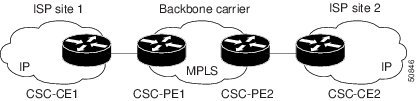

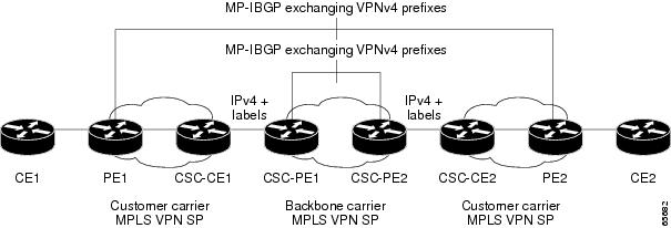
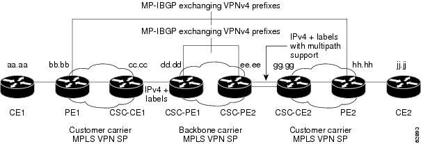
 Feedback