- Configuring ERSPAN
- Configuring Routing Between VLANs with IEEE 802.1Q Encapsulation
- IEEE 802.1Q-in-Q VLAN Tag Termination
- VLAN Mapping to Gigabit EtherChannel Member Links
- Configuring Routing Between VLANs
- EtherChannel Flow-Based Limited 1 1 Redundancy
- Flow-Based per Port-Channel Load Balancing
- VLANs over IP Unnumbered SubInterfaces
- Resilient Ethernet Protocol (REP)
- REP Access Gateway
- Spanning Tree Protocol
- Finding Feature Information
- Information About Spanning Tree Protocol
- How to Configure Spanning Tree Protocol
- Configuration Examples for Spanning Tree Protocol
- Additional References
- Feature Information for Spanning Tree Protocol
Spanning Tree Protocol
For conceptual information about Spanning Tree Protocol, see the “Using the Spanning Tree Protocol with the EtherSwitch Network Module” section of the EtherSwitch Network feature module.
- Finding Feature Information
- Information About Spanning Tree Protocol
- How to Configure Spanning Tree Protocol
- Configuration Examples for Spanning Tree Protocol
- Additional References
- Feature Information for Spanning Tree Protocol
Finding Feature Information
Your software release may not support all the features documented in this module. For the latest caveats and feature information, see Bug Search Tool and the release notes for your platform and software release. To find information about the features documented in this module, and to see a list of the releases in which each feature is supported, see the feature information table.
Use Cisco Feature Navigator to find information about platform support and Cisco software image support. To access Cisco Feature Navigator, go to www.cisco.com/go/cfn. An account on Cisco.com is not required.
Information About Spanning Tree Protocol
Using the Spanning Tree Protocol with the EtherSwitch Network Module
The EtherSwitch Network Module uses Spanning Tree Protocol (STP) (the IEEE 802.1D bridge protocol) on all VLANs. By default, a single instance of STP runs on each configured VLAN (provided that you do not manually disable STP). You can enable and disable STP on a per-VLAN basis.
When you create fault-tolerant internetworks, you must have a loop-free path between all nodes in a network. The spanning tree algorithm calculates the best loop-free path throughout a switched Layer 2 network. Switches send and receive spanning tree frames at regular intervals. The switches do not forward these frames but use the frames to construct a loop-free path.
Multiple active paths between end stations cause loops in the network. If a loop exists in the network, end stations might receive duplicate messages and switches might learn endstation MAC addresses on multiple Layer 2 interfaces. These conditions result in an unstable network.
STP defines a tree with a root switch and a loop-free path from the root to all switches in the Layer 2 network. STP forces redundant data paths into a standby (blocked) state. If a network segment in the spanning tree fails and a redundant path exists, the spanning tree algorithm recalculates the spanning tree topology and activates the standby path.
When two ports on a switch are part of a loop, the spanning tree port priority and port path cost setting determine which port is put in the forwarding state and which port is put in the blocking state. The spanning tree port priority value represents the location of an interface in the network topology and how well located it is to pass traffic. The spanning tree port path cost value represents media speed.
Spanning Tree Port States
Propagation delays occur when protocol information passes through a switched LAN. As a result, topology changes take place at different times and at different places in a switched network. When a Layer 2 interface changes from nonparticipation in the spanning tree topology to the forwarding state, it creates temporary data loops. Ports must wait for new topology information to propagate through the switched LAN before starting to forward frames. They must allow the frame lifetime to expire for frames that are forwarded using the old topology.
Each Layer 2 interface on a switch using Spanning Tree Protocol (STP) exists in one of the following states:
Blocking—The Layer 2 interface does not participate in frame forwarding.
Disabled—The Layer 2 interface does not participate in spanning tree and is not forwarding frames.
Forwarding—The Layer 2 interface forwards frames.
Learning—The Layer 2 interface prepares to participate in frame forwarding.
Listening—First transitional state after the blocking state when spanning tree determines that the Layer 2 interface must participate in frame forwarding.
A Layer 2 interface moves through the following states:
From blocking state to listening or disabled state.
From forwarding state to disabled state.
From initialization to blocking state.
From learning state to forwarding or disabled state.
From listening state to learning or disabled state.
The figure below illustrates how a port moves through these five states.
Boot-up Initialization
When you enable Spanning Tree Protocol (STP), every port in the switch, VLAN, or network goes through the blocking state and transitory states of listening and learning at power up. If properly configured, each Layer 2 interface stabilizes to the forwarding or blocking state.
When the spanning tree algorithm places a Layer 2 interface in the forwarding state, the following process occurs:
The Layer 2 interface is put into the listening state while it waits for protocol information to go to the blocking state.
The Layer 2 interface waits for the forward delay timer to expire, moves the Layer 2 interface to the learning state, and resets the forward delay timer.
The Layer 2 interface continues to block frame forwarding in the learning state as it learns end station location information for the forwarding database.
The Layer 2 interface waits for the forward delay timer to expire and then moves the Layer 2 interface to the forwarding state, where both learning and frame forwarding are enabled.
Blocking State
A Layer 2 interface in the blocking state does not participate in frame forwarding, as shown in the figure below. After initialization, a bridge protocol data unit (BPDU) is sent out to each Layer 2 interface in the switch. The switch initially assumes it is the root until it exchanges BPDUs with other switches. This exchange establishes which switch in the network is the root or root bridge. If only one switch is in the network, no exchange occurs, the forward delay timer expires, and the ports move to the listening state. A port enters the blocking state following switch initialization.
A Layer 2 interface in the blocking state performs as follows:
Discards frames received from the attached segment.
Discards frames switched from another interface for forwarding.
Does not incorporate end station location into its address database. (There is no learning on a blocking Layer 2 interface, so there is no address database update.)
Does not transmit BPDUs received from the system module.
Receives BPDUs and directs them to the system module.
Receives and responds to network management messages.
Listening State
The listening state is the first transitional state a Layer 2 interface enters after the blocking state. The Layer 2 interface enters this state when STP determines that the Layer 2 interface must participate in frame forwarding. The figure below shows a Layer 2 interface in the listening state.
A Layer 2 interface in the listening state performs as follows:
Discards frames received from the attached segment.
Discards frames switched from another interface for forwarding.
Does not incorporate end station location into its address database. (There is no learning on a blocking Layer 2 interface, so there is no address database update.)
Receives and directs BPDUs to the system module.
Receives, processes, and transmits BPDUs received from the system module.
Receives and responds to network management messages.
Learning State
The learning state prepares a Layer 2 interface to participate in frame forwarding. The Layer 2 interface enters the learning state from the listening state. The figure below shows a Layer 2 interface in the learning state.
A Layer 2 interface in the learning state performs as follows:
Discards frames received from the attached segment.
Discards frames switched from another interface for forwarding.
Incorporates end station location into its address database.
Receives BPDUs and directs them to the system module.
Receives, processes, and transmits BPDUs received from the system module.
Receives and responds to network management messages.
Forwarding State
A Layer 2 interface in the forwarding state forwards frames, as shown in the figure below. The Layer 2 interface enters the forwarding state from the learning state.
A Layer 2 interface in the forwarding state performs as follows:
Forwards frames received from the attached segment.
Forwards frames switched from another Layer 2 interface for forwarding.
Incorporates end station location information into its address database.
Receives BPDUs and directs them to the system module.
Processes BPDUs received from the system module.
Receives and responds to network management messages.
Disabled State
A Layer 2 interface in the disabled state does not participate in frame forwarding or spanning tree, as shown in the figure below. A Layer 2 interface in the disabled state is virtually nonoperational.
A Layer 2 interface in the disabled state performs as follows:
Discards frames received from the attached segment.
Discards frames switched from another Layer 2 interface for forwarding.
Does not incorporate end station location into its address database. (There is no learning on a blocking Layer 2 interface, so there is no address database update.)
Does not receive BPDUs for transmission from the system module.
Default Spanning Tree Configuration
The table below shows the default Spanning Tree Protocol (STP) configuration values.
|
Feature |
Default Value |
|---|---|
|
Bridge priority |
32768 |
|
Enable state |
Spanning tree enabled for all VLANs |
|
Forward delay time |
15 seconds |
|
Hello time |
2 seconds |
|
Maximum aging time |
20 seconds |
|
Spanning tree port cost (configurable on a per-interface basis; used on interfaces configured as Layer 2 access ports) |
Fast Ethernet: 19 Ethernet: 100 Gigabit Ethernet: 19 when operated in 100 Mb mode, and 4 when operated in 1000 Mb mode |
|
Spanning tree port priority (configurable on a per-interface basis; used on interfaces configured as Layer 2 access ports) |
128 |
|
Spanning tree VLAN port cost (configurable on a per-VLAN basis; used on interfaces configured as Layer 2 trunk ports) |
Fast Ethernet: 10 Ethernet: 10 |
|
Spanning tree VLAN port priority (configurable on a per-VLAN basis; used on interfaces configured as Layer 2 trunk ports) |
128 |
Bridge Protocol Data Units
The stable active spanning tree topology of a switched network is determined by the following:
-
Port identifier (port priority and MAC address) associated with each Layer 2 interface.
-
Spanning tree path cost to the root bridge.
-
Unique bridge ID (bridge priority and MAC address) associated with each VLAN on each switch.
The bridge protocol data units (BPDUs) are transmitted in one direction from the root switch and each switch sends configuration BPDUs to communicate and compute the spanning tree topology. Each configuration BPDU contains the following minimal information:
-
Bridge ID of the transmitting bridge
-
Message age
-
Port identifier of the transmitting port
-
Spanning tree path cost to the root
-
Unique bridge ID of the switch that the transmitting switch believes to be the root switch
-
Values for the hello, forward delay, and max-age protocol timers
When a switch transmits a BPDU frame, all switches connected to the LAN on which the frame is transmitted receive the BPDU. When a switch receives a BPDU, it does not forward the frame but uses the information in the frame to calculate a BPDU, and, if the topology changes, begin a BPDU transmission.
A BPDU exchange results in the following:
-
A designated bridge for each LAN segment is selected. This is the switch closest to the root bridge through which frames are forwarded to the root.
-
A root port is selected. This is the port providing the best path from the bridge to the root bridge.
-
One switch is elected as the root switch.
-
Ports included in the spanning tree are selected.
-
The shortest distance to the root switch is calculated for each switch based on the path cost.
For each VLAN, the switch with the highest bridge priority (the lowest numerical priority value) is elected as the root switch. If all switches are configured with the default priority (32768), the switch with the lowest MAC address in the VLAN becomes the root switch.
The spanning tree root switch is the logical center of the spanning tree topology in a switched network. All paths that are not needed to reach the root switch from anywhere in the switched network are placed in spanning tree blocking mode.
BPDUs contain information about the transmitting bridge and its ports, including bridge and MAC addresses, bridge priority, port priority, and path cost. Spanning tree uses this information to elect the root bridge and root port for the switched network, as well as the root port and designated port for each switched segment.
MAC Address Allocation
The MAC address allocation manager has a pool of MAC addresses that are used as bridge IDs for the VLAN spanning trees. In the table below, you can view the number of VLANs allowed for each platform.
|
Platform |
Maximum Number of VLANs Allowed |
|---|---|
|
Cisco 2600 |
32 VLANs |
|
Cisco 3640 or higher |
64 VLANs |
MAC addresses are allocated sequentially, with the first MAC address in the range assigned to VLAN 1, the second MAC address in the range assigned to VLAN 2, and so forth. For example, if the MAC address range is 00-e0-1e-9b-2e-00 to 00-e0-1e-9b-31-ff, the VLAN 1 bridge ID is 00-e0-1e-9b-2e-00, the VLAN 2 bridge ID is 00-e0-1e-9b-2e-01, the VLAN 3 bridge ID is 00-e0-1e-9b-2e-02, and so forth.
BackboneFast
BackboneFast is started when a root port or blocked port on a switch receives inferior bridge protocol data units (BPDUs) from its designated bridge. An inferior BPDU identifies one switch as both the root bridge and the designated bridge. When a switch receives an inferior BPDU, it means that a link to which the switch is not directly connected is failed. That is, the designated bridge has lost its connection to the root switch. Under Spanning Tree Protocol (STP) rules, the switch ignores inferior BPDUs for the configured maximum aging time specified by the spanning-tree max-age command.
The switch determines if it has an alternate path to the root switch. If the inferior BPDU arrives on a blocked port, the root port and other blocked ports on the switch become alternate paths to the root switch. If the inferior BPDU arrives on the root port, all blocked ports become alternate paths to the root switch. If the inferior BPDU arrives on the root port and there are no blocked ports, the switch assumes that it lost connectivity to the root switch, causes the maximum aging time on the root to expire, and becomes the root switch according to normal STP rules.
 Note | Self-looped ports are not considered as alternate paths to the root switch. |
If the switch possesses alternate paths to the root switch, it uses these alternate paths to transmit the protocol data unit (PDU) that is called the root link query PDU. The switch sends the root link query PDU on all alternate paths to the root switch. If the switch determines that it has an alternate path to the root, it causes the maximum aging time on ports on which it received the inferior BPDU to expire. If all the alternate paths to the root switch indicate that the switch has lost connectivity to the root switch, the switch causes the maximum aging time on the ports on which it received an inferior BPDU to expire. If one or more alternate paths connect to the root switch, the switch makes all ports on which it received an inferior BPDU its designated ports and moves them out of the blocking state (if they were in the blocking state), through the listening and learning states, and into the forwarding state.
The figure below shows an example topology with no link failures. Switch A, the root switch, connects directly to Switch B over link L1 and to Switch C over link L2. The interface on Switch C that connects directly to Switch B is in the blocking state.
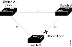
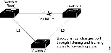
If link L1 fails, Switch C cannot detect this failure because it is not connected directly to link L1. However, Switch B is directly connected to the root switch over L1 and it detects the failure, elects itself as the root switch, and begins sending BPDUs to Switch C. When Switch C receives the inferior BPDUs from Switch B, Switch C assumes that an indirect failure has occurred. At that point, BackboneFast allows the blocked port on Switch C to move to the listening state without waiting for the maximum aging time for the port to expire. BackboneFast then changes the interface on Switch C to the forwarding state, providing a path from Switch B to Switch A. This switchover takes 30 seconds, twice the forward delay time, if the default forward delay time of 15 seconds is set. The figure below shows how BackboneFast reconfigures the topology to account for the failure of link L1.
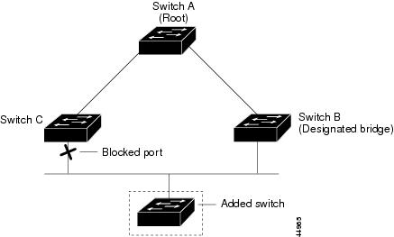
If a new switch is introduced into a shared-medium topology as shown in the figure below, BackboneFast is not activated because inferior BPDUs did not come from the designated bridge (Switch B). The new switch begins sending inferior BPDUs that say it is the root switch. However, the other switches ignore these inferior BPDUs, and the new switch learns that Switch B is the designated bridge to Switch A, the root switch.
STP Timers
The table below describes the Spanning Tree Protocol (STP) timers that affect the entire spanning tree performance.
|
Timer |
Purpose |
|---|---|
|
Forward delay timer |
Determines how long listening state and learning state last before the port begins forwarding. |
|
Hello timer |
Determines how often the switch broadcasts hello messages to other switches. |
|
Maximum age timer |
Determines how long a switch can store the protocol information received on a port. |
Spanning Tree Port Priority
Spanning tree considers port priority when selecting an interface to put into the forwarding state if there is a loop. You can assign higher priority values to interfaces that you want spanning tree to select first, and lower priority values to interfaces that you want spanning tree to select last. If all interfaces possess the same priority value, spanning tree puts the interface with the lowest interface number in the forwarding state and blocks other interfaces. The spanning tree port priority range is from 0 to 255, configurable in increments of 4. The default value is 128.
Cisco software uses the port priority value when an interface is configured as an access port and uses VLAN port priority values when an interface is configured as a trunk port.
Spanning Tree Port Cost
The spanning tree port path cost default value is derived from the media speed of an interface. if there is a loop, spanning tree considers port cost value when moving an interface to the forwarding state. You can assign lower port cost values to interfaces that you want spanning tree to select first and higher port cost values to interfaces that you want spanning tree to select last. If all interfaces have the same port cost value, spanning tree puts the interface with the lowest interface number to the forwarding state and blocks other interfaces.
The port cost range is from 0 to 65535. The default value is media-specific.
Spanning tree uses the port cost value when an interface is configured as an access port and uses VLAN port cost value when an interface is configured as a trunk port.
Spanning tree port cost value calculations are based on the bandwidth of the port. There are two classes of port cost values. Short (16-bit) values are specified by the IEEE 802.1D specification and the range is from 1 to 65535. Long (32-bit) values are specified by the IEEE 802.1t specification and the range is from 1 to 200,000,000.
Assigning Short Port Cost Values
You can manually assign port cost values in the range of 1 to 65535. Default port cost values are listed in Table 2.
|
Port Speed |
Default Port Cost Value |
|---|---|
|
10 Mbps |
100 |
|
100 Mbps |
19 |
Assigning Long Port Cost Values
You can manually assign port cost values in the range of 1 to 200,000,000. Default port cost values are listed in Table 3.
|
Port Speed |
Recommended Value |
Recommended Range |
|---|---|---|
|
10 Mbps |
2,000,000 |
200,000 to 20,000,000 |
|
100 Mbps |
200,000 |
20,000 to 2,000,000 |
Spanning Tree Root Bridge
The EtherSwitch HWIC maintains a separate instance of spanning tree for each active VLAN configured on the device. A bridge ID, consisting of the bridge priority and the bridge MAC address, is associated with each instance. For each VLAN, the device with the lowest bridge ID will become the root bridge for that VLAN.
To configure a VLAN instance to become the root bridge, the bridge priority can be modified from the default value (32768) to a lower value so that the bridge becomes the root bridge for the specified VLAN. Use the spanning-tree vlan root command to alter the bridge priority.
The device checks the bridge priority of current root bridges for each VLAN. The bridge priority for specified VLANs is set to 8192, if this value is caused the device to become the root for specified VLANs.
If any root device for specified VLANs has a bridge priority lower than 8192, the device sets the bridge priority for specified VLANs to 1 less than the lowest bridge priority.
For example, if all devices in a network have the bridge priority for VLAN 100 set to the default value of 32768, entering the spanning-tree vlan 100 root primary command on a device sets the bridge priority for VLAN 100 to 8192, causing the device to become the root bridge for VLAN 100.
Note | The root device for each instance of spanning tree must be a backbone or distribution device. Do not configure an access device as the spanning tree primary root. |
Use the diameter keyword to specify the Layer 2 network diameter. That is, the maximum number of bridge hops between any two end stations in the Layer 2 network. When you specify the network diameter, the device automatically picks an optimal hello time, a forward delay time, and a maximum age time for a network of that diameter, which reduces the spanning tree convergence time. You can use the hello keyword to override the automatically calculated hello time.
Note | We recommend that you do not configure the hello time, forward delay time, and maximum age time manually after you configure the device as the root bridge. |
How to Configure Spanning Tree Protocol
Enabling Spanning Tree Protocol
You can enable spanning tree protocol on a per-VLAN basis. The device maintains a separate instance of spanning tree for each VLAN except for which you disable spanning tree.
1.
enable
2.
configure
terminal
3.
spanning-tree vlan
vlan-id
4.
end
5.
show
spanning-tree
vlan
vlan-id
DETAILED STEPS
Configuring the Bridge Priority of a VLAN
1.
enable
2.
configure
terminal
3. spanning-tree vlan vlan-id priority bridge-priority
4.
show
spanning-tree
vlan
bridge
DETAILED STEPS
Configuring STP Timers
Configuring Hello Time
1.
enable
2.
configure
terminal
3. spanning-tree vlan vlan-id hello-time hello-time
4.
end
DETAILED STEPS
| Command or Action | Purpose | |
|---|---|---|
| Step 1 | enable
Example: Device> enable |
Enables privileged EXEC mode. |
| Step 2 | configure
terminal
Example: Device# configure terminal |
Enters global configuration mode. |
| Step 3 | spanning-tree
vlan
vlan-id
hello-time
hello-time
Example: Device(config)# spanning-tree vlan 200 hello-time 5 |
Configures the hello time for a VLAN. |
| Step 4 | end
Example: Device(config)# end |
Exits global configuration mode and enters privileged EXEC mode. |
Configuring the Forward Delay Time for a VLAN
1.
enable
2.
configure
terminal
3.
spanning-tree
vlan
vlan-id
forward-time
forward-time
4.
end
DETAILED STEPS
| Command or Action | Purpose | |
|---|---|---|
| Step 1 | enable
Example: Device> enable |
Enables privileged EXEC mode. |
| Step 2 | configure
terminal
Example: Device# configure terminal |
Enters global configuration mode. |
| Step 3 | spanning-tree
vlan
vlan-id
forward-time
forward-time
Example: Device(config)# spanning-tree vlan 20 forward-time 5 |
Configures the forward delay time for a VLAN. |
| Step 4 | end
Example: Device(config)# end |
Exits global configuration mode and enters privileged EXEC mode. |
Configuring the Maximum Aging Time for a VLAN
1.
enable
2.
configure
terminal
3. spanning-tree vlan vlan-id max-age max-age
4.
end
DETAILED STEPS
| Command or Action | Purpose | |
|---|---|---|
| Step 1 | enable
Example: Device> enable |
Enables privileged EXEC mode. |
| Step 2 | configure
terminal
Example: Device# configure terminal |
Enters global configuration mode. |
| Step 3 | spanning-tree
vlan
vlan-id
max-age
max-age
Example: Device(config)# spanning-tree vlan 200 max-age 30 |
Configures the maximum aging time for a VLAN. |
| Step 4 | end
Example: Device(config)# end |
Exits global configuration mode and enters privileged EXEC mode. |
Configuring Spanning Tree Port Priority
1.
enable
2.
configure
terminal
3.
interface
type number
4. spanning-tree port-priority port-priority
5. spanning-tree vlan vlan-id port-priority port-priority
6.
end
7.
show
spanning-tree
interface
fastethernet
interface-id
DETAILED STEPS
| Command or Action | Purpose | |
|---|---|---|
| Step 1 | enable
Example: Device> enable |
Enables privileged EXEC mode. |
| Step 2 | configure
terminal
Example: Device# configure terminal |
Enters global configuration mode. |
| Step 3 | interface
type number
Example: Device(config)# interface fastethernet 0/1/6 |
Configures an interface and enters interface configuration mode. |
| Step 4 | spanning-tree
port-priority
port-priority
Example: Device(config-if)# spanning-tree port-priority 8 |
Configures the port priority for an interface. |
| Step 5 | spanning-tree
vlan
vlan-id
port-priority
port-priority
Example: Device (config-if)# spanning-tree vlan vlan1 port-priority 12 |
Configures the port priority for a VLAN. |
| Step 6 | end
Example: Device(config)# end |
Exits global configuration mode and enters privileged EXEC mode. |
| Step 7 | show
spanning-tree
interface
fastethernet
interface-id
Example: Device# show spanning-tree interface fastethernet 0/1/6 |
(Optional) Saves your entries in the configuration file. |
Configuring Spanning Tree Port Cost
1.
enable
2.
configure
terminal
3.
interface
type number
4.
spanning-tree cost
port-cost
5.
spanning-tree vlan
vlan-id
cost
port-cost
6.
end
7.
show
spanning-tree
interface
fastethernet
interface-id
DETAILED STEPS
| Command or Action | Purpose | |
|---|---|---|
| Step 1 | enable
Example: Device> enable |
Enables privileged EXEC mode. |
| Step 2 | configure
terminal
Example: Device# configure terminal |
Enters global configuration mode. |
| Step 3 | interface
type number
Example: Device(config)# interface fastethernet 0/1/6 |
Configures an interface and enters interface configuration mode. |
| Step 4 | spanning-tree cost
port-cost
Example: Device(config-if)# spanning-tree cost 2000 |
Configures the port cost for an interface. |
| Step 5 | spanning-tree vlan
vlan-id
cost
port-cost
Example: Device(config-if)# spanning-tree vlan 200 cost 2000 |
Configures the VLAN port cost for an interface. |
| Step 6 | end
Example: Device(config)# end |
Exits interface configuration mode and enters privileged EXEC mode. |
| Step 7 | show
spanning-tree
interface
fastethernet
interface-id
Example: Device# show spanning-tree interface fastethernet 0/1/6 |
(Optional) Saves your entries in the configuration file. |
Configuring Spanning Tree Root Bridge
1.
enable
2.
configure
terminal
3.
spanning-tree vlan
vlanid
root
primary [diameter
hops [hello-time
seconds]]
4. no spanning-tree vlan vlan-id
5. show spanning-tree vlan vlan-id
DETAILED STEPS
| Command or Action | Purpose | |
|---|---|---|
| Step 1 | enable
Example: Device> enable |
Enables privileged EXEC mode. |
| Step 2 | configure
terminal
Example: Device# configure terminal |
Enters global configuration mode. |
| Step 3 | spanning-tree vlan
vlanid
root
primary [diameter
hops [hello-time
seconds]]
Example: Device(config)# spanning-tree vlan 200 root primary |
Configures a device as the root device. |
| Step 4 | no
spanning-tree
vlan
vlan-id
Example: Device(config)# no spanning-tree vlan 200 root primary |
Disables spanning tree on a per-VLAN basis. |
| Step 5 | show
spanning-tree
vlan
vlan-id
Example: Device(config)# show spanning-tree vlan 200 |
Verifies spanning tree on a per-VLAN basis. |
Verifying Spanning Tree on a VLAN
1.
enable
2.
show
spanning-tree
[bridge-group] [active |
backbonefast |
blockedports |
bridge |
brief |
inconsistentports |
interface
interface-type
interface-number |
pathcost
method |
root |
summary [totals] |
uplinkfast |
vlan
vlan-id]
DETAILED STEPS
| Step 1 |
enable
Enables privileged EXEC mode. Enter your password if prompted. Example: Device> enable |
| Step 2 |
show
spanning-tree
[bridge-group] [active |
backbonefast |
blockedports |
bridge |
brief |
inconsistentports |
interface
interface-type
interface-number |
pathcost
method |
root |
summary [totals] |
uplinkfast |
vlan
vlan-id]
Use this command with the vlan keyword to display the spanning tree information about a specified VLAN. Example: Device# show spanning-tree vlan 200
VLAN200 is executing the ieee compatible Spanning Tree protocol
Bridge Identifier has priority 32768, address 0050.3e8d.6401
Configured hello time 2, max age 20, forward delay 15
Current root has priority 16384, address 0060.704c.7000
Root port is 264 (FastEthernet5/8), cost of root path is 38
Topology change flag not set, detected flag not set
Number of topology changes 0 last change occurred 01:53:48 ago
Times: hold 1, topology change 24, notification 2
hello 2, max age 14, forward delay 10
Timers: hello 0, topology change 0, notification 0
Example: Port 264 (FastEthernet5/8) of VLAN200 is forwarding Port path cost 19, Port priority 128, Port Identifier 129.9. Designated root has priority 16384, address 0060.704c.7000 Designated bridge has priority 32768, address 00e0.4fac.b000 Designated port id is 128.2, designated path cost 19 Timers: message age 3, forward delay 0, hold 0 Number of transitions to forwarding state: 1 BPDU: sent 3, received 3417 Use this command with the interface keyword to display spanning tree information about a specified interface. Example: Device# show spanning-tree interface fastethernet 5/8 Port 264 (FastEthernet5/8) of VLAN200 is forwarding Port path cost 19, Port priority 100, Port Identifier 129.8. Designated root has priority 32768, address 0010.0d40.34c7 Designated bridge has priority 32768, address 0010.0d40.34c7 Designated port id is 128.1, designated path cost 0 Timers: message age 2, forward delay 0, hold 0 Number of transitions to forwarding state: 1 BPDU: sent 0, received 13513 Use this command with the bridge, brief, and vlan keywords to display the bridge priority information. Example: Device# show spanning-tree bridge brief vlan 200 Hello Max Fwd Vlan Bridge ID Time Age Delay Protocol ---------------- -------------------- ---- ---- ----- -------- VLAN200 33792 0050.3e8d.64c8 2 20 15 ieee |
Configuration Examples for Spanning Tree Protocol
Example: Enabling Spanning Tree Protocol
The following example shows how to enable spanning tree protocol on VLAN 20:
Device# configure terminal
Device(config)# spanning-tree vlan 20
Device(config)# end
Device#
Note | Because spanning tree is enabled by default, the show running command will not display the command you entered to enable spanning tree protocol. |
The following example shows how to disable spanning tree protocol on VLAN 20:
Device# configure terminal
Device(config)# no spanning-tree vlan 20
Device(config)# end
Device#
Example: Configuring the Bridge Priority of a VLAN
The following example shows how to configure the bridge priority of VLAN 20 to 33792:
Device# configure terminal
Device(config)# spanning-tree vlan 20 priority 33792
Device(config)# end
Example: Configuring STP Timers
Example: Configuring Hello Time
The following example shows how to configure the hello time for VLAN 20 to 7 seconds:
Device# configure terminal
Device(config)# spanning-tree vlan 20 hello-time 7
Device(config)# end
Example: Configuring the Forward Delay Time for a VLAN
The following example shows how to configure the forward delay time for VLAN 20 to 21 seconds:
Device#configure terminal
Device(config)#spanning-tree vlan 20 forward-time 21
Device(config)#end
Example: Configuring the Maximum Aging Time for a VLAN
The following example shows how to configure the maximum aging time for VLAN 20 to 36 seconds:
Device#configure terminal
Device(config)#spanning-tree vlan 20 max-age 36
Device(config)#end
Example: Configuring Spanning Tree Port Priority
The following example shows how to configure VLAN port priority on an interface:
Device# configure terminal
Device(config)# interface fastethernet 0/3/2
Device(config-if)# spanning-tree vlan 20 port priority 64
Device(config-if)# end
The following example shows how to verify the configuration of VLAN 20 on an interface when it is configured as a trunk port:
Device#show spanning-tree vlan 20

 VLAN20 is executing the ieee compatible Spanning Tree protocol
  Bridge Identifier has priority 32768, address 00ff.ff90.3f54
  Configured hello time 2, max age 20, forward delay 15
  Current root has priority 32768, address 00ff.ff10.37b7
  Root port is 33 (FastEthernet0/3/2), cost of root path is 19
  Topology change flag not set, detected flag not set
  Number of topology flags 0 last change occurred 00:05:50 ago
  Times: hold 1, topology change 35, notification 2
     hello 2, max age 20, forward delay 15
  Timers: hello 0, topology change 0, notification 0, aging 0
 Port 33 (FastEthernet0/3/2) of VLAN20 is forwarding
  Port path cost 18, Port priority 64, Port Identifier 64.33
  Designated root has priority 32768, address 00ff.ff10.37b7
  Designated bridge has priority 32768, address 00ff.ff10.37b7
  Designated port id is 128.13, designated path cost 0
  Timers: message age 2, forward delay 0, hold 0
  Number of transitions to forwarding state: 1
  BPDU: sent 1, received 175
Example: Configuring Spanning Tree Port Cost
The following example shows how to change the spanning tree port cost of a Fast Ethernet interface:
Device# configure terminal
Device(config)# interface fastethernet0/3/2
Device(config-if)# spanning-tree cost 18
Device(config-if)# end
Device#
Device# show run interface fastethernet0/3/2
Building configuration...
Current configuration: 140 bytes
!
interface FastEthernet0/3/2
 switchport access vlan 20
  no ip address
  spanning-tree vlan 20 port-priority 64
  spanning-tree cost 18
end
The following example shows how to verify the configuration of a Fast Ethernet interface when it is configured as an access port:
Device# show spanning-tree interface fastethernet0/3/2

 Port 33 (FastEthernet0/3/2) of VLAN20 is forwarding
  Port path cost 18, Port priority 64, Port Identifier 64.33
  Designated root has priority 32768, address 00ff.ff10.37b7
  Designated bridge has priority 32768, address 00ff.ff10.37b7
  Designated port id is 128.13, designated path cost 0
  Timers: message age 2, forward delay 0, hold 0
  Number of transitions to forwarding state: 1
  BPDU: sent 1, received 175
Example: Configuring Spanning Tree Root Bridge
The following example shows how to configure the spanning tree root bridge for VLAN 10, with a network diameter of 4:
Device# configure terminal
Device(config)# spanning-tree vlan 10 root primary diameter 4
Device(config)# exit
Additional References
Related Documents
Related Topic |
Document Title |
|---|---|
|
Cisco IOS commands |
|
|
LAN switching commands |
|
Technical Assistance
Description |
Link |
|---|---|
|
The Cisco Support and Documentation website provides online resources to download documentation, software, and tools. Use these resources to install and configure the software and to troubleshoot and resolve technical issues with Cisco products and technologies. Access to most tools on the Cisco Support and Documentation website requires a Cisco.com user ID and password. |
Feature Information for Spanning Tree Protocol
The following table provides release information about the feature or features described in this module. This table lists only the software release that introduced support for a given feature in a given software release train. Unless noted otherwise, subsequent releases of that software release train also support that feature.
Use Cisco Feature Navigator to find information about platform support and Cisco software image support. To access Cisco Feature Navigator, go to www.cisco.com/go/cfn. An account on Cisco.com is not required.Feature Name |
Releases |
Feature Information |
|---|---|---|
|
Spanning Tree Protocol |
12.1(1)E |
Spanning Tree Protocol (STP) is a Layer 2 link management protocol that provides path redundancy while preventing undesirable loops in the network. The following commands were introduced or modified: spanning-tree vlan, spanning-tree port-priority, and spanning-tree cost. |
|
|
|
 Feedback