- Finding Feature Information
- Prerequisites for VLAN Mapping to GEC Member Links
- Restrictions for VLAN Mapping to GEC Member Links
- Information About VLAN Mapping of GEC Member Links
- How to Configure VLAN Mapping to GEC Links
- Configuration Examples for VLAN Mapping to GEC Member Links
- Additional References
- Feature Information for VLAN Mapping to GEC Member Links
VLAN Mapping to Gigabit EtherChannel Member Links
The VLAN Mapping to Gigabit EtherChannel (GEC) Member Links feature allows you to configure static assignment of user traffic as identified by a VLAN ID to a given member link of a GEC bundle. You can manually assign VLAN subinterfaces to a primary and secondary link. This feature includes load balancing to downstream equipment, regardless of vendor equipment capabilities, and provides failover protection by redirecting traffic to the secondary member link if the primary link fails. Member links are supported with up to 16 bundles per chassis.
- Finding Feature Information
- Prerequisites for VLAN Mapping to GEC Member Links
- Restrictions for VLAN Mapping to GEC Member Links
- Information About VLAN Mapping of GEC Member Links
- How to Configure VLAN Mapping to GEC Links
- Configuration Examples for VLAN Mapping to GEC Member Links
- Additional References
- Feature Information for VLAN Mapping to GEC Member Links
Finding Feature Information
Your software release may not support all the features documented in this module. For the latest feature information and caveats, see the release notes for your platform and software release. To find information about the features documented in this module, and to see a list of the releases in which each feature is supported, see the Feature Information Table at the end of this document.
Use Cisco Feature Navigator to find information about platform support and Cisco software image support. To access Cisco Feature Navigator, go to www.cisco.com/go/cfn. An account on Cisco.com is not required.
Prerequisites for VLAN Mapping to GEC Member Links
- Per-VLAN load balancing must be globally enabled.
- Each VLAN must have IEEE 802.1Q encapsulation configured.
- One primary and one secondary link must be associated with each VLAN.
Restrictions for VLAN Mapping to GEC Member Links
The following restrictions are applicable for IPv6 load balancing on GEC links:
Information About VLAN Mapping of GEC Member Links
- VLAN-to-Port Channel Member Link Mapping
- VLAN-Manual Load Balancing
- VLAN Primary and Secondary Link Association
- Adding Channel Member Links
- Deleting Member Links
- EC Link Down Notification
- EC Link Up Notification
VLAN-to-Port Channel Member Link Mapping
The figure below illustrates the traffic flow for the VLAN-to-port channel mapping.
| Figure 1 | VLAN-to-Port Channel Mapping |
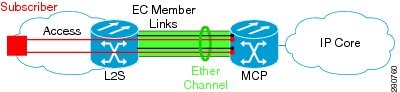
The black lines represent the physical 1 GigabitEthernet interfaces connecting the MCP router with the Layer 2 (L2) switch. These interfaces are bundled together in port-channels, shown in green.
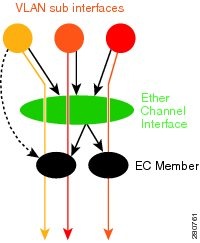
In the figure below, subscriber VLAN subinterfaces, shown in shades of orange and red, are configured as Layer 3 (L3) interfaces on top of the EtherChannel interfaces. Mapping of the VLAN to the member link (shown with the dotted black arrow) is done through configuration and downloaded in the dataplane so that outgoing VLA traffic (shown with orange and red arrows) is sent over the associated active primary or secondary member link. The QoS configuration in this model is applied at the VLAN subinterface and member link interface level, implying that QoS queues are created at both levels.
| Figure 2 | Mapping of VLAN to Member Links |
VLAN-Manual Load Balancing
When load balancing is configured for GEC links, traffic flows are mapped to different buckets as dictated by the load balancing algorithm. For each EtherChannel configured, a set of 16 buckets are created. The EtherChannel module decides how buckets are distributed across member links. Each bucket has an active link associated with it that represents the interface to be used for all flows that are mapped to the same bucket.
All packets to be forwarded over the same VLAN subinterface are considered to be part of the same flow that is mapped to one bucket. Each bucket is associated with a primary-secondary pair, and the buckets point to the active interface in the pair. Only one of the pair is active at a time. Multiple VLAN flows can be mapped to the same bucket if their (primary, secondary) mapping is the same.
The buckets are created when VLAN manual load balancing is enabled. When VLAN load balancing is removed, the buckets are deleted. All port channels use either VLAN manual load balancing or dynamic flow-based load balancing. For information about flow-based load balancing, see the Flow-Based Per Port-Channel Load Balancing chapter.
VLAN Primary and Secondary Link Association
For port-channel traffic distribution, a member link has a configured state, primary or secondary, and an operational state, active or standby. The primary link is also active when the interface is up. If the primary interface is down, the interface is in primary standby state while the secondary interface is in secondary active state. If the primary link is up, the secondary link is in secondary standby, even if the interface is operationally up.
A primary and a secondary member link are each associated with each routed VLAN configured on a port-channel main interface. When forwarding traffic for this VLAN, the primary interface is used as the outgoing interface when this interface is up, the secondary interface, if operational, is used when the primary interface is down.
If not all the conditions for per-VLAN traffic distribution are met, the mapping is not downloaded in the forwarding plane. Otherwise, the dataplane is updated with this mapping.
The table below describes the primary and secondary link configuration status and the resulting function of each configuration.
| Table 1 | VLAN Primary and Secondary Link Mapping Status |
| Primary Status |
Secondary Status |
Description |
|---|---|---|
| Configured |
Configured |
Both primary and secondary links are specified with the encapsulation dot1q command. encapsulation dot1Q vlan-id primary interface-number secondary interface-number |
| Defaulted |
Defaulted |
Neither a primary nor secondary link is specified. encapsulation dot1Q vlan-id In a stable system, defaults for both primary and secondary links are selected in the same way for all VLANs. The first link up that is added to the EC is selected as primary, and the second link up as secondary. If there are no links up, the primary and secondary links are selected from the down links. |
| Configured |
Defaulted |
Only the primary link is specified. encapsulation dot1Q vlan-id primary interface-number A secondary link that is different than the primary link is internally selected. |
| Configured |
- |
Only a primary link is specified, and only one link is defined. encapsulation dot1Q vlan-id primary interface-number No secondary link can be selected as default when only one link is defined in the EC. |
| Defaulted |
- |
Neither a primary nor secondary link is specified, and only one link is defined. encapsulation dot1Q vlan-id A default for a primary link is selected, but no default can be selected for a secondary link if only one link is defined in the EC. |
| - |
- |
Neither a primary nor secondary link is specified, and no links are defined. encapsulation dot1Q vlan-id Defaults cannot be selected, and no links are defined in the EC. |
 Note |
Default mappings do not override user-configured mappings, even if the user-configured mappings are defined incorrectly. Once the (VLAN, primary, secondary) association is performed (either through CLI, defaults or combination), the system validates the mapping and downloads it to the dataplane. If there are no VLANs configured, all traffic forwarded over the port channel is dropped. |
Adding Channel Member Links
When a new member link is added, new buckets are created and downloaded in the dataplane. For all VLANs that have this interface as either primary or secondary new VLAN-to-bucket mappings are downloaded in the dataplane. For all VLANs that need a default for primary and secondary, the default selection algorithm is triggered, and if QoS validation passes, the VLAN-to-bucket mappings are downloaded. QoS policies create VLAN queues on the newly added link.
Deleting Member Links
When a member link is removed, a warning message is displayed. The VLAN queues from the link that is about to be deleted, VLAN-to-bucket mappings are removed, and all affected buckets are removed.
EC Link Down Notification
When a link goes down, all the traffic for the VLANs that have this link assigned as primary have to be switched to the links that are designated as secondary if the secondary link is up. The traffic for the VLANs that have this link assigned as secondary is not affected. The EC Link Down notification causes all buckets associated with a primary-secondary pair where the primary link is the down link and the secondary link is up to be updated with the secondary link. The change is communicated to the dataplane.
All buckets associated with a primary-secondary pair where secondary link is the down link and where primary link is down to be updated so that the primary is now the active link. The change is communicated to the dataplane.
EC Link Up Notification
When a link goes up, all the traffic for the VLANs that have this link assigned as primary is switched to this link. The traffic for the VLANs that have this link assigned as secondary is not affected. The EC Link Up notification causes all buckets associated with a primary-secondary pair where primary link is the link that came up and where secondary link is up to be notified that the primary link is up. The change is communicated to the dataplane.
All buckets associated with a primary-secondary pair where secondary link is the link that went up and where primary link is down are notified that the secondary link is now the primary link. The change is communicated to the dataplane.
How to Configure VLAN Mapping to GEC Links
- Configuring VLAN-Based Manual Load Balancing
- Disabling Load Balancing on the EtherChannel
- Removing a Member Link from the EtherChannel
Configuring VLAN-Based Manual Load Balancing
Perform this task to configure VLAN port-channel linking and to enable VLAN load balancing on port channels.
One primary and one secondary link must be associated with a given VLAN. The primary and secondary options are available only if VLAN manual load balancing is enabled. If all of the following conditions are met, the load balancing information is downloaded in the forwarding plane. If any of these conditions is no longer met, the load balancing information is removed from the forwarding plane.
- VLAN load balancing must be enabled globally.
- IEEE 802.1Q encapsulation must be configured on each VLAN.
- One primary and one secondary member link must be enabled to manually map the VLAN traffic to the EtherChannel links.
- The primary and secondary links must be part of the port channel for traffic to use these links.
If only a primary link is specified, a default secondary different from the specified primary is selected as the default. If neither the primary nor the secondary link is explicitly configured, a primary and a secondary link are selected by default. There is no attempt to perform equal VLAN distribution across links when default links are chosen.
If the interfaces specified as primary or secondary are not configured as part of the port channel, or if the global VLAN load balancing is not enabled, warning messages are displayed.
Note |
VLAN 500's main interface is not the channel group of primary=GigabitEthernet 4/0/1 Per-VLAN manual load-balancing will not take effect until channel-group is configured under the primary interface. VLAN 500's main interface is not the channel group of secondary=GigabitEthernet 1/0/0 Per-VLAN manual load-balancing will not take effect until channel-group is configured under the primary interface. |
DETAILED STEPS
Troubleshooting Tips
Disabling Load Balancing on the EtherChannel
To disable load balancing on the EtherChannel, use the no port-channel load-balancing vlan-manual command. When this command is issued, a warning message is displayed if any VLAN subinterfaces exist:
Warning: Removing the Global VLAN LB command will affect traffic for all dot1Q VLANs
Removing a Member Link from the EtherChannel
To remove a member link from the EtherChannel (EC), use the no channel-groupcommand
When a member link is removed from EC, if the link is included in a VLAN mapping, the following warning message is displayed:
Warning: Removing GigabitEthernet 4/0/0 from the port-channel will affect traffic for the dot1Q VLANs that include this link in their mapping.
Configuration Examples for VLAN Mapping to GEC Member Links
Example: VLAN Load Balancing
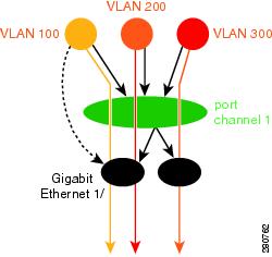
This example shows a load balancing configuration, including QoS features that might be applied to define policies for handling traffic. This example enables load balancing globally using the port-channel load-balancing command. Note that IEEE 802.1Q encapsulation is configured on each port-channel interface. The figure below illustrates the port channel bundle with the three VLANs used in the following configuration example:
| Figure 3 | Port Channel Bundle |
port-channel load-balancing vlan-manual
!
class-map match-all BestEffort
!
class-map match-all video
!
class-map match-all voice
!
policy-map subscriber
  class voice
    priority level 1
  class video
    priority level 2
  class class-default service-fragment BE
    shape average 10000
    bandwidth remaining percent 80
policy-map aggregate-member-link
    class BestEffort service-fragment BE
    shape average 100000
!
interface Port-channel1
 ip address 172.1.2.3 255.255.0.0
!
interface Port-channel1.100
 encapsulation dot1Q 100 primary GigabitEthernet 1/1/1
	             secondary GigabitEthernet 1/2/1
 ip address 172.1.2.100 255.255.255.0
 service-policy output subscriber
!
interface Port-channel1.200
 encapsulation dot1Q 200 primary GigabitEthernet 1/2/1
 ip address 172.1.2.200 255.255.255.0
 service-policy output subscriber
!
interface Port-channel1.300
 encapsulation dot1Q 300
 ip address 172.1.2.300 255.255.255.0
 service-policy output subscriber
!
interface GigabitEthernet 1/1/1
 no ip address
 channel-group 1 mode on
 service-policy output aggregate-member-link
!
interface GigabitEthernet 1/2/1
 no ip address
 channel-group 1 mode on
 service-policy output aggregate-member-link
Example: Troubleshooting
Example 1:
Router# show etherchannel load-balancing
EtherChannel Load-Balancing Configuration:
        vlan-manual
Example 2:
Router# show etherchannel load-balancing
EtherChannel Load-Balancing Configuration: not configured
Use the show interfaces port-channel command to display the traffic distribution currently in use.
Router# show interfaces port-channel 1 etherchannel

Active Member List contains 0 interfaces
 Passive Member List contains 2 interfaces
  Port: GigabitEthernet 4/0/0
    VLAN 1 (Pri, Ac, D, P)    VLAN 100 (Pri, Ac, C, P)    VLAN 200 (Sec, St, C, P)
  Port: GigabitEthernet 1/0/0
    VLAN 1 (Sec, St, D, P)    VLAN 100 (Sec, St, C, P)    VLAN 200 (Pri, Ac, C, P)
 Bucket Information for VLAN Manual LB:
    Bucket 0   (p=GigabitEthernet 4/0/0, s=GigabitEthernet 4/0/0) active GigabitEthernet 4/0/0
    Bucket 1   (p=Gigabitthernet 4/0/0, s=GigabitEthernet 1/0/0) active GigabitEthernet 4/0/0
    Bucket 4   (p=GigabitEthernet 1/0/0, s=GigabitEthernet 4/0/0) active GigabitEthernet 1/0/0
    Bucket 5   (p=GigabitEthernet 1/0/0, s=GigabitEthernet 1/0/0) active GigabitEthernet 1/0/0
To see the mapping of a VLAN to the primary and secondary links, use the show vlans command.
Router# show vlans 100
VLAN ID: 100 (IEEE 802.1Q Encapsulation)
   Protocols Configured:          Received:        Transmitted:
VLAN trunk interfaces for VLAN ID 100:
Port-channel1.1 (100)
      Mapping for traffic load-balancing using bucket 1:
          primary   = GigabitEthernet 4/0/0 (active, C, P)
          secondary = GigabitEthernet 1/0/0 (standby, C, P)
      Total 0 packets, 0 bytes input
      Total 0 packets, 0 bytes output
No subinterface configured with ISL VLAN ID 100
Additional References
Related Documents
| Related Topic |
Document Title |
|---|---|
| Cisco IOS commands |
|
| LAN Switching commands |
Cisco IOS LAN Switching Command Reference |
Technical Assistance
| Description |
Link |
|---|---|
| The Cisco Support and Documentation website provides online resources to download documentation, software, and tools. Use these resources to install and configure the software and to troubleshoot and resolve technical issues with Cisco products and technologies. Access to most tools on the Cisco Support and Documentation website requires a Cisco.com user ID and password. |
Feature Information for VLAN Mapping to GEC Member Links
The following table provides release information about the feature or features described in this module. This table lists only the software release that introduced support for a given feature in a given software release train. Unless noted otherwise, subsequent releases of that software release train also support that feature.
Use Cisco Feature Navigator to find information about platform support and Cisco software image support. To access Cisco Feature Navigator, go to www.cisco.com/go/cfn. An account on Cisco.com is not required.
| Table 2 | Feature Information for VLAN Mapping to Gigabit EtherChannel Member Links |
| Feature Name |
Releases |
Feature Information |
|---|---|---|
| VLAN Mapping to Gigabit EtherChannel Member Links |
Cisco IOS XE Release 2.1 |
The VLAN Mapping to Gigabit EtherChannel Member Links feature allows you to configure static assignment of user traffic as identified by a VLAN ID to a given member link of a GEC bundle. You can manually assign VLAN subinterfaces to a primary and secondary link. This feature includes load balancing to downstream equipment, regardless of vendor equipment capabilities, and provides failover protection by redirecting traffic to the secondary member link if the primary link fails. Member links are supported with up to 16 bundles per chassis. The following commands were modified by this feature: encapsulation dot1q, port-channel load-balancing vlan-manual, show etherchannel load-balancing, show interfaces port-channel vlan mapping. |
Cisco and the Cisco logo are trademarks or registered trademarks of Cisco and/or its affiliates in the U.S. and other countries. To view a list of Cisco trademarks, go to this URL: www.cisco.com/go/trademarks. Third-party trademarks mentioned are the property of their respective owners. The use of the word partner does not imply a partnership relationship between Cisco and any other company. (1110R)
Any Internet Protocol (IP) addresses and phone numbers used in this document are not intended to be actual addresses and phone numbers. Any examples, command display output, network topology diagrams, and other figures included in the document are shown for illustrative purposes only. Any use of actual IP addresses or phone numbers in illustrative content is unintentional and coincidental.
 Feedback