- Configuring LAN Interfaces
- Configuring Serial Interfaces
- Circuit Emulation over IP
- Lossless Compression R1 ATM Cell Switching and External BITS Clocking Source
- Minimal Disruptive Restart of VIP Cards
- Rate Based Satellite Control Protocol
- Configuring Virtual Interfaces
- ImplementingTunnels
- Dynamic Layer 3 VPNs with Multipoint GRE Tunnels
- MPLS VPN over mGRE
- IP Tunnel MIBs
- IF-MIBs
- Managing Dial Shelves
- Router-Shelf Redundancy for the Cisco AS5800
- Route-Switch-Controller Handover Redundancy on the Cisco AS5850
- Route Processor Redundancy Plus
- Finding Feature Information
- Prerequisites for Dynamic L3 VPNs with mGRE Tunnels
- Restrictions for Dynamic L3 VPNs with mGRE Tunnels
- Information About Dynamic L3 VPNs with mGRE Tunnels
Dynamic Layer 3 VPNs with Multipoint GRE Tunnels
The Dynamic Layer 3 VPNs with Multipoint GRE Tunnels feature provides a Layer 3 (L3) transport mechanism based on an enhanced multipoint generic routing encapsulation (mGRE) tunneling technology for use in IP networks. The dynamic Layer 3 tunneling transport can also be used within IP networks to transport Virtual Private Network (VPN) traffic across service provider and enterprise networks, and to provide interoperability for packet transport between IP and Multiprotocol Label Switching (MPLS) VPNs. This feature provides support for RFC 2547, which defines the outsourcing of IP backbone services for enterprise networks.
- Finding Feature Information
- Prerequisites for Dynamic L3 VPNs with mGRE Tunnels
- Restrictions for Dynamic L3 VPNs with mGRE Tunnels
- Information About Dynamic L3 VPNs with mGRE Tunnels
- How to Configure L3 VPN mGRE Tunnels
- Configuration Examples for Dynamic L3 VPNs Support Using mGRE Tunnels
- Additional References
- Feature Information for Dynamic L3 VPNs with mGRE Tunnels
Finding Feature Information
Your software release may not support all the features documented in this module. For the latest feature information and caveats, see the release notes for your platform and software release. To find information about the features documented in this module, and to see a list of the releases in which each feature is supported, see the Feature Information for Dynamic L3 VPNs with mGRE Tunnels.
Use Cisco Feature Navigator to find information about platform support and Cisco IOS and Catalyst OS software image support. To access Cisco Feature Navigator, go to http://www.cisco.com/go/cfn. An account on Cisco.com is not required.
Prerequisites for Dynamic L3 VPNs with mGRE Tunnels
Before you configure the Dynamic Layer 3 VPNs with Multipoint GRE Tunnels feature, ensure that your MPLS VPN is configured and working properly. See the "Configuring MPLS Layer 3 VPNs" module for information about setting up MPLS VPNs.
Restrictions for Dynamic L3 VPNs with mGRE Tunnels
- The deployment of a MPLS VPN using both IP/GRE and MPLS encapsulation within a single network is not supported.
- Each provider edge (PE) router supports one tunnel configuration only.
Information About Dynamic L3 VPNs with mGRE Tunnels
You can configure mGRE tunnels to create a multipoint tunnel network that overlays an IP backbone. This overlay connects PE routers to transport VPN traffic. To deploy L3 VPN mGRE tunnels, you create a VRF instance, create the mGRE tunnel, redirect the VPN IP traffic to the tunnel, and set up the BGP VPNv4 exchange so that updates are filtered through a route map and interesting prefixes are resolved in the VRF table.
In addition, when MPLS VPNs are configured over mGRE, you can deploy L3 PE-based VPN services using a standards-based IP core. This allows you to provision the VPN services without using the overlay method. When an MPLS VPN over mGRE is configured, the system uses IPv4-based mGRE tunnels to encapsulate VPN-labeled IPv4 and IPv6 packets between PEs.
Layer 3 mGRE Tunnels
By configuring mGRE tunnels, you create a multipoint tunnel network as an overlay to the IP backbone. This overlay interconnects the PE routers to transport VPN traffic through the backbone. This multipoint tunnel network uses Border Gateway Protocol (BGP) to distribute VPNv4 routing information between PE routers, maintaining the peer relationship between the service provider or enterprise network and customer sites. The advertised next hop in BGP VPNv4 triggers tunnel endpoint discovery. This feature provides the ability for multiple service providers to cooperate and offer a joint VPN service with traffic tunneled directly from the ingress PE router at one service provider directly to the egress PE router at a different service provider site.
In addition to providing the VPN transport capability, the mGRE tunnels create a full-mesh topology and reduce the administrative and operational overhead previously associated with a full mesh of point-to-point tunnels used to interconnect multiple customer sites. The configuration requirements are greatly reduced and enable the network to grow with minimal additional configuration.
Dynamic L3 tunnels provide for better scaling when creating partial-mesh or full-mesh VPNs. Adding new remote VPN peers is simplified because only the new router needs to be configured. The new address is learned dynamically and propagated to the nodes in the network. The dynamic routing capability dramatically reduces the size of configuration needed on all routers in the VPN, such that with the use of multipoint tunnels, only one tunnel interface needs to be configured on a PE that services many VPNs. The L3 mGRE tunnels need to be configured only on the PE router. Features available with GRE are still available with mGRE, including dynamic IP routing and IP multicast and Cisco Express Forwarding (CEF) switching of mGRE/Next Hop Routing Protocol (NHRP) tunnel traffic.
The following sections describe how the mGRE tunnels are used:
- Interconnecting Provider Edge Routers Within an IP Network
- Packet Transport Between IP and MPLS Networks
- BGP Next Hop Verification
Interconnecting Provider Edge Routers Within an IP Network
The Dynamic Layer 3 VPNs with Multipoint GRE Tunnels feature allows you to create a multiaccess tunnel network to interconnect the PE routers that service your IP network. This tunnel network transports IP VPN traffic to all of the PE routers. The figure below illustrates the tunnel overlay network used in an IP network to transport VPN traffic between the PE routers.
| Figure 1 | mGRE Tunnel Overlay Connecting PE Routers Within an IP Network |
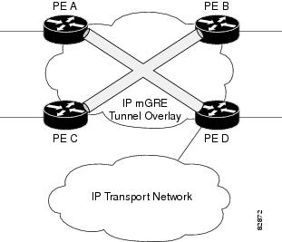
The multiaccess tunnel overlay network provides full connectivity between PE routers. The PE routers exchange VPN routes by using BGP as defined in RFC 2547. IP traffic is redirected through the multipoint tunnel overlay network using distinct IP address spaces for the overlay and transport networks and by changing the address space instead of changing the numerical value of the address.
Packet Transport Between IP and MPLS Networks
Layer 3 mGRE tunnels can be used as a packet transport mechanism between IP and MPLS networks. To enable the packet transport between the two different protocols, one PE router on one side of the connection between the two networks must run MPLS. The figure below shows how mGRE tunnels can be used to transport VPN traffic between PE routers.
| Figure 2 | mGRE Used to Transport VPN Traffic Between IP and MPLS Network |
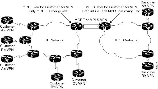
For the packet transport to occur between the IP and MPLS network, the MPLS VPN label is mapped to the GRE key. The mapping takes place on the router where both mGRE and MPLS are configured. In the figure above the mapping of the label to the key occurs on Router M, which sits on the MPLS network.
BGP Next Hop Verification
BGP performs the BGP path selection, or next hop verification, at the PE. For a BGP path to a network to be considered in the path selection process, the next hop for the path must be reachable in the Interior Gateway Protocol (IGP). When an IP prefix is received and advertised as the next hop IP address, the IP traffic is tunneled from the source to the destination by switching the address space of the next hop.
How to Configure L3 VPN mGRE Tunnels
- Creating the VRF and mGRE Tunnel
- Setting Up BGP VPN Exchange
- Enabling the MPLS VPN over mGRE Tunnels and Configuring an L3VPN Encapsulation Profile
- Defining the Address Space and Specifying Address Resolution for MPLS VPNs over mGRE
Creating the VRF and mGRE Tunnel
The tunnel that transports the VPN traffic across the service provider network resides in its own address space. A special VRF instance must be created called Resolve in VRF (RiV). This section describes how to create the VRF and GRE tunnel.
The IP address on the interface should be the same as that of the source interface specified in the configuration. The source interface specified should match that used by BGP as a source for the VPNv4 update.
 Note |
Tunnel mode IPSec is not supported on MPLS over GRE Tunnel. |
DETAILED STEPS
Setting Up BGP VPN Exchange
The configuration task described in this section sets up the BGP VPNv4 exchange so that the updates are filtered through a route map and interesting prefixes are resolved in the VRF table.
DETAILED STEPS
Enabling the MPLS VPN over mGRE Tunnels and Configuring an L3VPN Encapsulation Profile
This section describes how to define the VRF, enable MPLS VPN over mGRE, and configure an L3VPN encapsulation profile.
Note |
Transport protocols such as IPv6, MPLS, IP, and Layer 2 Tunneling Protocol version 3 (L2TPv3) can also be used in this configuration. |
To enable and configure MPLS VPN over mGRE, you must first define the VRF for tunnel encapsulation and enable L3VPN encapsulation in the system.
DETAILED STEPS
Defining the Address Space and Specifying Address Resolution for MPLS VPNs over mGRE
This section describes how to define the address space and specify the address resolution for MPLS VPNs over mGRE. The following steps also enable you to link the route map to the application template and set up the BGP VPNv4 and VPNv6 exchange so that updates are filtered through the route map.
DETAILED STEPS
What to Do Next
You can perform the following to make sure that the configuration is working properly.
Check the VRF Prefix
Verify that the specified VRF prefix has been received by BGP. The BGP table entry should show that the route map has worked and that the next hop is showing in the RiV. Use the show ip bgp vpnv4 command as shown in this example.
Router# show ip bgp vpnv4 vrf customer 209.165.200.250
BGP routing table entry for 100:1:209.165.200.250/24, version 12
Paths: (1 available, best #1)
  Not advertised to any peer
  Local
209.165.200.251 in "my riv" from 209.165.200.251 (209.165.200.251)
      Origin incomplete, metric 0, localpref 100, valid, internal, best
      Extended Community: RT:100:1
Confirm that the same information has been propagated to the routing table:
Router# show ip route vrf customer 209.165.200.250

Routing entry for 209.165.200.250
/24
  Known via "bgp 100", distance 200, metric 0, type internal
  Last update from 209.165.200.251 00:23:07 ago
  Routing Descriptor Blocks:
  * 209.165.200.251 (my riv), from 209.165.200.251, 00:23:07 ago
      Route metric is 0, traffic share count is 1
      AS Hops 0
CEF Switching
You can also verify that CEF switching is working as expected:
Router# show ip cef vrf customer
 209.165.200.250

209.165.200.250
/24, version 6, epoch 0
0 packets, 0 bytes
  tag information set
    local tag: VPN-route-head
    fast tag rewrite with Tu1, 123.1.1.2, tags imposed: {17}
  via 209.165.200.251, 0 dependencies, recursive
    next hop 209.165.200.251, Tunnel1 via 209.165.200.251/32 (my riv)
    valid adjacency
    tag rewrite with Tu1, 209.165.200.251, tags imposed: {17}
Endpoint Creation
Note that in this example display the tunnel endpoint has been created correctly:
Router# show tunnel endpoint tunnel 1
Tunnel1 running in multi-GRE/IP mode
  RFC2547/L3VPN Tunnel endpoint discovery is active on Tu1
  Transporting l3vpn traffic to all routes recursing through "my riv"
 Endpoint 209.165.200.251 via destination 209.165.200.251
 Endpoint 209.165.200.254 via destination 209.165.200.254
Adjacency
Confirm that the corresponding adjacency has been created.
Router# show adjacency Tunnel 1 interface
Protocol Interface                 Address
TAG      Tunnel1                   209.165.200.251(4)
                                   15 packets, 1980 bytes
                                   4500000000000000FF2FC3C77B010103
                                   7B01010200008847
                                   Epoch: 0
                                   Fast adjacency disabled
                                   IP redirect disabled
                                   IP mtu 1472 (0x0)
                                   Fixup enabled (0x2)
                                         GRE tunnel
                                   Adjacency pointer 0x624A1580, refCount 4
                                   Connection Id 0x0
                                   Bucket 121
Note that because MPLS is being transported over mGRE, the LINK_TAG adjacency is the relevant adjacency. The MTU reported in the adjacency is the payload length (including the MPLS label) that the packet will accept. The MAC string shown in the adjacency display can be interpreted as follows:
45000000 -> Beginning of IP Header (Partially populated, tl & chksum
00000000    are fixed up per packet)
FF2FC3C7
7B010103 -> Source IP Address in transport network 209.165.200.253
7B010102 -> Destination IP address in transport network 209.165.200.252
00008847 -> GRE Header
Refer to the Cisco IOS Multiprotocol Label Switching Configuration Guide for information about configuring MPLS Layer 3 VPNs.
You can use the show l3vpn encapsulation profile-name command to get information on the basic state of the application. The output of this command provides you details on the references to the tunnel and VRF.
Configuration Examples for Dynamic L3 VPNs Support Using mGRE Tunnels
Configuring Layer 3 VPN mGRE Tunnels Example
This example shows the configuration sequence for creating mGRE tunnels. It includes the definition of the special VRF instance.
ip vrf my riv
 rd 1:1
interface Tunnel1
 ip vrf forwarding my_riv
 ip address 209.165.200.250 255.255.255.224
 tunnel source Loopback0
 tunnel mode gre multipoint l3vpn
 tunnel key 123
end
ip route vrf my riv ip address subnet mask Tunnel1
router bgp 100
 network 209.165.200.251
 neighbor 209.165.200.250 remote-as 100
 neighbor 209.165.200.250 update-source Loopback0
 !
 address-family vpnv4
 neighbor 209.165.200.250 activate
 neighbor 209.165.200.250 route-map SELECT_UPDATES_FOR_L3VPN_OVER_MGRE in
!
route-map SELECT UPDATES FOR L3VPN OVER MGRE permit 10
 set ip next-hop in-vrf my riv
This example shows the configuration to link a route map to the application:
vrf definition Customer A
 rd 100:110
 route-target export 100:1000
 route-target import 100:1000
 !
 address-family ipv4
 exit-address-family
 !
 address-family ipv6
 exit-address-family
!
vrf definition tunnel encap
 rd 1:1
!
 address-family ipv4
 exit-address-family
 !
 address-family ipv6
 exit-address-family
!
!
ip cef
!
ipv6 unicast-routing
ipv6 cef
!
!
l3vpn encapsulation ip profile name
 transport source loopback 0
 protocol gre key 1234
!
!
 interface Loopback0
  ip address 209.165.200.252 255.255.255.224
  ip router isis
!
interface Serial2/0
 vrf forwarding Customer A
 ip address 209.165.200.253 255.255.255.224
 ipv6 address 3FFE:1001::/64 eui-64
 no fair-queue
 serial restart-delay 0
!
router bgp 100
 bgp log-neighbor-changes
 neighbor 209.165.200.254 remote-as 100
 neighbor 209.165.200.254 update-source Loopback0
 !
 address-family ipv4
  no synchronization
  redistribute connected
  neighbor 209.165.200.254 activate
  no auto-summary
 exit-address-family
 !
 address-family vpnv4
  neighbor 209.165.200.254 activate
  neighbor 209.165.200.254 send-community both
  neighbor 209.165.200.254 route-map SELECT UPDATE FOR L3VPN in
 exit-address-family
 !
 address-family vpnv6
  neighbor 209.165.200.254 activate
  neighbor 209.165.200.254 send-community both
  neighbor 209.165.200.254 route-map SELECT UPDATE FOR L3VPN in
 exit-address-family
 !
 address-family ipv4 vrf Customer A
  no synchronization
  redistribute connected
 exit-address-family
 !
 address-family ipv6 vrf Customer A
  redistribute connected
  no synchronization
 exit-address-family
!
!
route-map SELECT UPDATE FOR L3VPN permit 10
set ip next-hop encapulate <profile_name>
set ipv6 next-hop encapsulate <profile_name>
Additional References
For additional information related to dynamic L3 VPN mGRE tunnels, refer to the following references:
Related Documents
| Related Topic |
Document Title |
|---|---|
| Configuring MPLS Layer 3 VPNs |
Cisco IOS Multiprotocol Label Switching Configuration Guide |
| MPLS VPN Over mGRE |
Cisco IOS Interface and Hardware Component Configuration Guide |
| Cisco Express Forwarding |
Cisco IOS IP Switching Configuration Guide |
| Generic Routing Encapsulation |
Cisco IOS Interface and Hardware Component Configuration Guide |
Standards
| Standard |
Title |
|---|---|
| None |
-- |
MIBs
| MIB |
MIBs Link |
|---|---|
| IETF-PPVPN-MPLS-VPN-MIB |
To locate and download MIBs for selected platforms, Cisco IOS releases, and feature sets, use Cisco MIB Locator found at the following URL: |
RFCs
| RFC |
Title |
|---|---|
| RFC 2547 |
BGP/MPLS VPNs |
| RFC 2784 |
Generic Routing Encapsulation (GRE) |
| RFC 2890 |
Key Sequence Number Extensions to GRE |
| RFC 4023 |
Encapsulating MPLS in IP or Generic Routing Encapsulation |
| RFC 4364 |
BGP/MPLS IP Virtual Private Networks (VPNs) |
Technical Assistance
| Description |
Link |
|---|---|
| The Cisco Support and Documentation website provides online resources to download documentation, software, and tools. Use these resources to install and configure the software and to troubleshoot and resolve technical issues with Cisco products and technologies. Access to most tools on the Cisco Support and Documentation website requires a Cisco.com user ID and password. |
Feature Information for Dynamic L3 VPNs with mGRE Tunnels
The following table provides release information about the feature or features described in this module. This table lists only the software release that introduced support for a given feature in a given software release train. Unless noted otherwise, subsequent releases of that software release train also support that feature.
Use Cisco Feature Navigator to find information about platform support and Cisco software image support. To access Cisco Feature Navigator, go to www.cisco.com/go/cfn. An account on Cisco.com is not required.
| Table 1 | Feature Information for Dynamic L3 VPNs with mGRE Tunnels |
| Feature Name |
Releases |
Feature Information |
|---|---|---|
| Dynamic Layer 3 VPNs with Multipoint GRE Tunnels |
12.0(23)S |
This feature provides an L3 transport mechanism based on an enhanced mGRE tunneling technology for use in IP networks. |
Cisco and the Cisco logo are trademarks or registered trademarks of Cisco and/or its affiliates in the U.S. and other countries. To view a list of Cisco trademarks, go to this URL: www.cisco.com/go/trademarks. Third-party trademarks mentioned are the property of their respective owners. The use of the word partner does not imply a partnership relationship between Cisco and any other company. (1110R)
Any Internet Protocol (IP) addresses and phone numbers used in this document are not intended to be actual addresses and phone numbers. Any examples, command display output, network topology diagrams, and other figures included in the document are shown for illustrative purposes only. Any use of actual IP addresses or phone numbers in illustrative content is unintentional and coincidental.
 Feedback