- Configuring ATM
- AAL1 CES on AIM-ATM
- DHCP Client on WAN Interfaces
- Lossless Compression and ATM Cell Switching and BITS Clocking
- ATM Multilink PPP Support on Multiple VCs
- ATM OAM Support for F5 Continuity Check
- ATM OAM Ping
- ATM Policing by Service Category for SVC SoftPVC
- Configuring ATM SNMP Trap and OAM Enhancements
- ATM SVC Troubleshooting Enhancements
- ATM Software Segmentation and Reassembly
- Unspecified Bit Rate Plus and ATM Enhancements
- Enhanced Voice and QoS for ADSL and G.SHDSL
- End of Life for Multiprotocol over ATM
- Multiprotocol over ATM Overview
- Configuring the Multiprotocol over ATM Client
- Configuring the Multiprotocol over ATM Server
- Configuring Token Ring LAN Emulation MPOA
- MPLS Diff-Serv-aware Traffic Engineering over ATM
- End of Life for LAN Emulation
- LAN Emulation Overview
- Configuring LAN Emulation
- Configuring Token Ring LAN Emulation
- SNMP Trap Support for the Virtual Switch Interface Master MIB
- VLAN 0 Priority Tagging Support
- Preserve 802.1Q Tagging with 802.1P Marking over ATM PVCs for xDSL Uplinks
- Reuse MAC for ATM Route-Bridge Encapsulation
- Index
- Finding Feature Information
- Feature History
- Background and Overview
- Platforms and Interfaces Supported
- Supported Standards
- Prerequisites
- Configuration Tasks
- Verifying the Configurations
- Tunnel Head
- Midpoint Devices
- Tail-End Device
- Guaranteed Bandwidth Service Configuration
- Guaranteed Bandwidth Service Examples
- Example with Single Destination Prefix
MPLS Diff-Serv-aware Traffic Engineering over ATM
This guide presents extensions made to Multiprotocol Label Switching Traffic Engineering (MPLS TE) that make it Diff-Serv aware and applicable across ATM networks. The bandwidth reservable on each link for constraint-based routing (CBR) purposes can now be managed through two bandwidth pools: a global pool and a sub-pool. The sub-pool can be limited to a smaller portion of the link bandwidth. Tunnels using the sub-pool bandwidth can then be used in conjunction with MPLS Quality of Service (QoS) mechanisms to deliver guaranteed bandwidth services end-to-end across the network.
 Caution | The Fast Reroute feature of traffic engineering is not supported on ATM interfaces. |
- Finding Feature Information
- Feature History
- Background and Overview
- Platforms and Interfaces Supported
- Supported Standards
- Prerequisites
- Configuration Tasks
- Configuration Examples
- Command Reference
- Glossary
Finding Feature Information
Your software release may not support all the features documented in this module. For the latest caveats and feature information, see Bug Search Tool and the release notes for your platform and software release. To find information about the features documented in this module, and to see a list of the releases in which each feature is supported, see the feature information table.
Use Cisco Feature Navigator to find information about platform support and Cisco software image support. To access Cisco Feature Navigator, go to www.cisco.com/go/cfn. An account on Cisco.com is not required.
Feature History
|
Release |
Modification |
|---|---|
|
12.0(11) ST |
DS-TE feature introduced. |
|
12.0(14) ST |
Support added for IS-IS Interior Gateway Protocol. |
|
12.0(14) ST-1 |
Support added for guaranteed bandwidth service directed to many destination prefixes (for example, guaranteed bandwidth service destined to an autonomous system or to a BGP community). |
|
12.2(4) T |
Support added for Cisco Series 7200 platform and for ATM-PVC interface. |
|
12.2(8) T |
Support added for LC-ATM interface. |
Background and Overview
MPLS traffic engineering allows constraint-based routing of IP traffic. One of the constraints satisfied by CBR is the availability of required bandwidth over a selected path. Diff-Serv-aware Traffic Engineering extends MPLS traffic engineering to enable you to perform constraint-based routing of "guaranteed" traffic, which satisfies a more restrictive bandwidth constraint than that satisfied by CBR for regular traffic. The more restrictive bandwidth is termed a sub-pool, while the regular TE tunnel bandwidth is called the global pool. (The sub-pool is a portion of the global pool.) This ability to satisfy a more restrictive bandwidth constraint translates into an ability to achieve higher Quality of Service performance (in terms of delay, jitter, or loss) for the guaranteed traffic.
For example, DS-TE can be used to ensure that traffic is routed over the network so that, on every link, there is never more than 40 per cent (or any assigned percentage) of the link capacity of guaranteed traffic (for example, voice), while there can be up to 100 per cent of the link capacity of regular traffic. Assuming QoS mechanisms are also used on every link to queue guaranteed traffic separately from regular traffic, it then becomes possible to enforce separate "overbooking" ratios for guaranteed and regular traffic. (In fact, for the guaranteed traffic it becomes possible to enforce no overbooking at all--or even an underbooking--so that very high QoS can be achieved end-to-end for that traffic, even while for the regular traffic a significant overbooking continues to be enforced.)
Also, through the ability to enforce a maximum percentage of guaranteed traffic on any link, the network administrator can directly control the end-to-end QoS performance parameters without having to rely on over-engineering or on expected shortest path routing behavior. This is essential for transport of applications that have very high QoS requirements (such as real-time voice, virtual IP leased line, and bandwidth trading), where over-engineering cannot be assumed everywhere in the network.
DS-TE involves extending OSPF (Open Shortest Path First routing protocol), so that the available sub-pool bandwidth at each preemption level is advertised in addition to the available global pool bandwidth at each preemption level. And DS-TE modifies constraint-based routing to take this more complex advertised information into account during path computation.
Benefits
Diff-Serv-aware Traffic Engineering enables service providers to perform separate admission control and separate route computation for discrete subsets of traffic (for example, voice and data traffic).
Therefore, by combining DS-TE with other IOS features such as QoS, the service provider can:
Develop QoS services for end customers based on signaled rather than provisioned QoS
Build the higher-revenue generating "strict-commitment" QoS services, without over-provisioning
Offer virtual IP leased-line, Layer 2 service emulation, and point-to-point guaranteed bandwidth services including voice-trunking
Enjoy the scalability properties offered by MPLS
Related Features and Technologies
The DS-TE feature is related to OSPF, IS-IS, RSVP (Resource reSerVation Protocol), QoS, and MPLS traffic engineering. Cisco documentation for all of these features is listed in the next section.
Related Documents
For OSPF:
"Configuring OSPF" in Cisco IOS Release 12.1 IP and IP Routing Configuration Guide.
"OSPF Commands" in Cisco IOS Release 12.1 IP and IP Routing Command Reference.
For IS-IS:
"Configuring Integrated IS-IS" in Cisco IOS Release 12.1 IP and IP Routing Configuration Guide.
"Integrated IS-IS Commands" in Cisco IOS Release 12.1 Cisco IOS IP and IP Routing Command Reference.
For RSVP:
"Configuring RSVP" in Cisco IOS Release 12.1 Quality of Service Solutions Configuration Guide.
IP RSVP commands section in Cisco IOS Release 12.1 Quality of Service Solutions Command Reference.
For QoS:
Cisco IOS Release 12.1 Quality of Service Solutions Configuration Guide.
Cisco IOS Release 12.1 Quality of Service Solutions Command Reference.
For MPLS Traffic Engineering:
Cisco IOS Release 12.1(3)T MPLS Traffic Engineering and Enhancements
"Multiprotocol Label Switching" in Cisco IOS Release 12.1 Switching Services Configuration Guide.
Section containing MPLS commands in Cisco IOS Release 12.1 Switching Services Command Reference.
For ATM:
ATM-PVC: the "Configuring ATM" chapter of the Release 12.2 Cisco IOS Wide-Area Networking Configuration Guide.
ATM-LSR: the "Configuring Trunks and Adding Interface Shelves" chapter of the Release 9.3.30 BPX 8600 Series Installation and Configuration Guide http://www.cisco.com/univercd/cc/td/doc/product/wanbu/bpx8600/9_3_3/iandc/bpxi18.htm and the Release 9.3.10 Update to the Cisco WAN Switch Command Reference Guide http://www.cisco.com/univercd/cc/td/doc/product/wanbu/bpx8600/9_3_1/update/udcmdref.htm
Platforms and Interfaces Supported
This release supports DS-TE together with QoS on the POS, ATM-PVC, and LC-ATM interfaces of the Cisco 7200 and 7500 Series Routers.
To carry DS-TE tunnels through an MPLS ATM cloud, an ATM-LSR should contain a Cisco 7200 router (functioning as its Label Switch Controller) and any one of the following ATM switches:
To check for changes in platform support since the publication of this document, access Feature Navigator at http://www.cisco.com/go/fn . You must have an account on Cisco.com . Qualified users can establish an account by following directions at http://www.cisco.com/register .
If you have forgotten or lost your account information, send a blank e-mail to cco-locksmith@cisco.com. An automatic check will verify that your e-mail address is registered, and account details with a new random password will then be e-mailed to you.
Supported Standards
Standardization of Diff-Serv-aware MPLS Traffic Engineering is still in progress in the IETF (Internet Engineering Task Force). At the time of publication of this feature guide, DS-TE has been documented in the following IETF drafts:
Requirements for Support of Diff-Serv-aware MPLS Traffic Engineering by F. Le Faucheur, T. Nadeau, A. Chiu, W. Townsend, D. Skalecki & M. Tathamhttp://search.ietf.org/internet-drafts/draft-ietf-tewg-diff-te-reqts-nn.txt
Protocol Extensions for Support of Diff-Serv-aware MPLS Traffic Engineering by F. Le Faucheur, T. Nadeau, J. Boyle, K. Kompella, W. Townsend & D. Skaleckihttp://search.ietf.org/internet-drafts/draft-ietf-tewg-diff-te-proto-01.txt
As the IETF work is still in progress, details are still under definition and subject to change, so DS-TE should be considered as a pre-standard implementation of IETF DiffServ-aware MPLS Traffic Engineering. However, it is in line with the requirements described in the first document above.The concept of "Class-Type" defined in that IETF draft corresponds to the concept of bandwidth pool implemented by DS-TE. And because DS-TE supports two bandwidth pools (global pool and sub-pool), DS-TE should be seen as supporting two Class-Types (Class-Type 0 and Class-Type 1).
Prerequisites
Your network must support the following Cisco IOS features in order to support guaranteed bandwidth services based on Diff-Serv-aware Traffic Engineering:
MPLS
IP Cisco Express Forwarding (CEF)
OSPF or ISIS
RSVP-TE
QoS
Configuration Tasks
This section lists the minimum set of commands you need to implement the Diff-Serv-aware Traffic Engineering feature--in other words, to establish a tunnel that reserves bandwidth from the sub-pool.
The subsequent "Configuration Examples" section (page 14), presents these same commands in context and shows how, by combining them with QoS commands, you can build guaranteed bandwidth services.
New Commands
DS-TE commands were developed from the existing command set that configures MPLS traffic engineering. The only difference introduced to create DS-TE was the expansion of two commands:
ip rsvp bandwidth was expanded to configure the size of the sub-pool on every link.
tunnel mpls traffic-eng bandwidth was expanded to enable a TE tunnel to reserve bandwidth from the sub-pool.
The ip rsvp bandwidth command
The old command was
ip rsvp bandwidth x y
where x = the size of the only possible pool, and y = the size of a single traffic flow (ignored by traffic engineering)
Now the extended command is
ip rsvp bandwidth x y sub-pool z
where x = the size of the global pool, and z = the size of the sub-pool.
(Remember, the sub-pool’s bandwidth is less than--because it is part of--the global pool’s bandwidth.)
The tunnel mpls traffic-eng bandwidth command
The old command was
tunnel mpls traffic-eng bandwidth b
where b = the amount of bandwidth this tunnel requires.
Now you specify from which pool (global or sub) the tunnel's bandwidth is to come. You can enter
tunnel mpls traffic-eng bandwidth sub-pool b
This indicates that the tunnel should use bandwidth from the sub-pool. Alternatively, you can enter
tunnel mpls traffic-eng bandwidth b
This indicates that the tunnel should use bandwidth from the global pool (the default).
 Note | As can be seen in the Guaranteed Bandwidth Service Examples section ( page 24), when QoS commands are added to DS-TE commands, guaranteed bandwidth tunnels can be created. To accomplish that across an MPLS ATM cloud, two more commands were created (beginning with Release 12.2(8)T): mpls traffic-eng atm cos global-poo l and mpls traffic-eng atm cos sub-pool. |
The Configuration Procedure
To establish a sub-pool TE tunnel, you must enter configurations at three levels:
the device (router, switch router, or label switch router)
the physical interface (network interface)
the tunnel interface
On the first two levels, you activate traffic engineering (and certain ATM settings if the tunnel will cross an ATM cloud). On the third level--the tunnel interface--you establish the sub-pool tunnel. Therefore, it is only at the tunnel headend device that you need to configure all three levels. At the tunnel midpoints and tail, it is sufficient to configure the first two levels.
In the tables below, each command is explained in brief. For a more complete explanation of any command, refer to the page given in the right-hand column.
- Level 1: Configuring the Device
- Level 2: Configuring the Network Interface
- Level 3: Configuring the Tunnel Interface
- ATM-LSR Special Case
Level 1: Configuring the Device
At this level, you tell the device (router or switch router) to use accelerated packet-forwarding (known as Cisco Express Forwarding or CEF), MultiProtocol Label Switching (MPLS), traffic-engineering tunneling, and either the OSPF or IS-IS routing algorithm (Open Shortest Path First or Intermediate System to Intermediate System). This level is often called global configuration mode because the configuration is applied globally, to the entire device, rather than to a specific interface or routing instance.
You enter the following commands:
1. Router(config)# ip cef
2. Router(config)# mpls traffic-eng tunnels
3. Router(config)# mpls traffic-eng atm cos sub-pool
4. Router(config)# router ospf
5. Router (config-router)# net network-entity-title
6. Router (config-router)# metric-style wide
7. Router (config-router)# is-type level -n
8. Router (config-router)# mpls traffic-eng level -n
9. Router (config-router)# passive-interface loopback0
10. Router(config-router)# mpls traffic-eng router-id loopback0
11. Router(config-router)# mpls traffic-eng area num
DETAILED STEPS
| Command or Action | Purpose | |
|---|---|---|
| Step 1 | Router(config)# ip cef |
Enables CEF--which accelerates the flow of packets through the device. |
| Step 2 | Router(config)# mpls traffic-eng tunnels |
Enables MPLS, and specifically its traffic engineering tunnel capability. |
| Step 3 |
Router(config)# mpls traffic-eng atm cos sub-pool Example: Example: Example:
Router(config)# mpls traffic-eng atm cos global-pool
|
[To be used only on ATM-LSR devices that are midpoints of a DS-TE tunnel]. Maps the queue carrying sub-pool traffic onto the highest cell-based class of service. (Optional). Maps the queue carrying global pool traffic onto one of the remaining three classes of service. |
| Step 4 |
Router(config)# router ospf Example: Example: Example: [or] Example:
Router(config)# router isis
|
Invokes the OSPF routing process for IP and puts the device into router configuration mode. Proceed now to Steps 10and 11. Alternatively, you may invoke the ISIS routing process with this command and continue with Step 5. |
| Step 5 | Router (config-router)# net network-entity-title |
Specifies the IS-IS network entity title (NET) for the routing process. |
| Step 6 | Router (config-router)# metric-style wide |
Enables the router to generate and accept IS-IS new-style TLVs (type, length, and value objects). |
| Step 7 | Router (config-router)# is-type level -n |
Configures the router to learn about destinations inside its own area or "IS-IS level". |
| Step 8 | Router (config-router)# mpls traffic-eng level -n |
Specifies the IS-IS level (which must be the same level as in the preceding step) to which the router will flood MPLS traffic- engineering link information. |
| Step 9 | Router (config-router)# passive-interface loopback0 |
Instructs IS-IS to advertise the IP address of the loopback interface without actually running IS-IS on that interface. Continue with Step 10 but don’t do Step 11--because Step 11 refers to OSPF. |
| Step 10 | Router(config-router)# mpls traffic-eng router-id loopback0 |
Specifies that the traffic engineering router identifier is the IP address associated with the loopback0 interface. |
| Step 11 | Router(config-router)# mpls traffic-eng area num |
Turns on MPLS traffic engineering for a particular OSPF area. |
Level 2: Configuring the Network Interface
Having configured the device, you now must configure the interface on that device through which the tunnel will run. To do that, you first put the router into interface-configuration mode.
You then enable Resource Reservation Protocol (RSVP). RSVP is used to signal (set up) a traffic engineering tunnel, and to tell devices along the tunnel path to reserve a specific amount of bandwidth for the traffic that will flow through that tunnel. It is with this command that you establish the maximum size of the sub-pool.
Finally, you enable the MPLS traffic engineering tunnel feature on this network interface--and if you will be relying on the IS-IS routing protocol, you enable that as well. (In the case of ATM-PVC and LC-ATM interfaces you must enable IS-IS on a sub -interface level, and you must enable MPLS on both the interface and the sub-interface levels.)
To accomplish these tasks, you enter the following commands. (Step 7 or 8 is entered only when the interface you are configuring is either an ATM-PVC - Step 7 - or an LC-ATM - Step 8).
1. Router(config)# interface interface-id
2. Router(config-if)# ip rsvp bandwidth interface-kbps sub-pool kbps
3. Router(config-if)# mpls traffic-eng tunnels
4. Router(config-if)# interface interface-id.int-sub [mpls]
5. Router(config-subif)# ip rsvp bandwidth interface-kbps sub-pool kbps
6. Router(config-subif)# mpls traffic-eng tunnels
7. Router(config-subif)# atm pvc vcd vpi vci aal5snap
8. Router(config-subif)# mpls atm vpi-vpi
9. Router(config-subif)# ip router isis
10. Router(config-subif)# exit
11. Router(config-if)# ip router isis
DETAILED STEPS
| Command or Action | Purpose | |
|---|---|---|
| Step 1 | Router(config)# interface interface-id |
Moves configuration to the interface level, directing subsequent configuration commands to the specific interface identified by the interface-id. |
| Step 2 | Router(config-if)# ip rsvp bandwidth interface-kbps sub-pool kbps |
Enables RSVP on this interface and limits the amount of bandwidth RSVP can reserve on this interface. The sum of bandwidth used by all tunnels on this interface cannot exceed interface-kbps, and the sum of bandwidth used by all sub-pool tunnels cannot exceed sub-pool kbps. |
| Step 3 | Router(config-if)# mpls traffic-eng tunnels |
Enables the MPLS traffic engineering tunnel feature on this interface. If the tunnel will go through an ATM-PVC or LC-ATM interface, continue on through Steps 4 through 11. However, if the tunnel will go through a POS interface, skip immediately to Step 11. |
| Step 4 | Router(config-if)# interface interface-id.int-sub [mpls] |
Moves configuration to the sub-interface level, directing subsequent configuration commands to the specific sub-interface identified by the interface-id.sub-int. Needed when the tunnel will traverse an ATM-PVC or LC-ATM interface. The keyword mpls is needed only with the LC-ATM interface. |
| Step 5 | Router(config-subif)# ip rsvp bandwidth interface-kbps sub-pool kbps |
Enables RSVP on the sub-interface and limits the amount of bandwidth RSVP can reserve on the sub-interface. The sum of bandwidth used by all tunnels on this sub-interface cannot exceed interface-kbps, and the sum of bandwidth used by all sub-pool tunnels cannot exceed sub-pool kbps. |
| Step 6 | Router(config-subif)# mpls traffic-eng tunnels |
Enables the MPLS traffic engineering tunnel feature on this sub-interface. If interface is ATM-PVC, continue with Step 7. If instead the interface is LC-ATM, skip to Step 8.] |
| Step 7 | Router(config-subif)# atm pvc vcd vpi vci aal5snap |
Sets the ATM PVC descriptor, path identifier, and channel identifier. Also sets the encapsulation as AAL5SNAP. [Now skip ahead to Step 9.] |
| Step 8 | Router(config-subif)# mpls atm vpi-vpi |
Sets the range of Virtual Path Identifiers on the LC-ATM interface. |
| Step 9 | Router(config-subif)# ip router isis |
Enables the IS-IS routing protocol on the sub-interface. Do not enter this command if you are configuring for OSPF. |
| Step 10 | Router(config-subif)# exit |
Exits the sub-interface level, returning to the interface level. |
| Step 11 | Router(config-if)# ip router isis |
If you are configuring an interface that does not have sub-interfaces, like POS, you enable IS-IS routing protocol at this step, on the interface level. (More on page 68.) Do not enter this command if you are configuring for OSPF. |
Level 3: Configuring the Tunnel Interface
Now you create a set of attributes for the tunnel itself; those attributes are configured on the "tunnel interface" (not to be confused with the network interface just configured above).
The only command at this level which was affected to create DS-TE is tunnel mpls traffic-eng bandwidth (described in detail on page 145).
You enter the following commands:
1. Router(config)# interface tunnel1
2. Router(config-if)# tunnel destination A.B.C.D
3. Router(config-if)# tunnel mode mpls traffic-eng
4. Router(config-if)# tunnel mpls traffic-eng bandwidth{sub-pool | [global]} bandwidth
5. Router(config-if)# tunnel mpls traffic-eng priority
6. Router(config-if)# tunnel mpls traffic-eng path-option
DETAILED STEPS
| Command or Action | Purpose | |
|---|---|---|
| Step 1 | Router(config)# interface tunnel1 |
Creates a tunnel interface (named in this example tunnel1) and enters interface configuration mode. (More on page 62.) |
| Step 2 |
Router(config-if)# tunnel destination A.B.C.D Example: |
Specifies the IP address of the tunnel tail device. (More on page 139.) |
| Step 3 | Router(config-if)# tunnel mode mpls traffic-eng |
Sets the tunnel’s encapsulation mode to MPLS traffic engineering. (More on page 141.) |
| Step 4 | Router(config-if)# tunnel mpls traffic-eng bandwidth{sub-pool | [global]} bandwidth |
Configures the tunnel’s bandwidth and assigns it either to the sub-pool or the global pool. (More on page 145). |
| Step 5 | Router(config-if)# tunnel mpls traffic-eng priority |
Sets the priority to be used when system determines which existing tunnels are eligible to be preempted. (More on page 148). |
| Step 6 | Router(config-if)# tunnel mpls traffic-eng path-option |
Configures the paths (hops) a tunnel should use. The user can enter an explicit path (can specify the IP addresses of the hops) or can specify a dynamic path (the router figures out the best set of hops). (More on page 147). |
ATM-LSR Special Case
Because of the joint nature of the ATM-LSR device--being both a router running Cisco IOS and an ATM switch running its own, different operating system--distinct configuration tasks are required to have this device convey DS-TE tunnels across itself as a tunnel midpoint. (The ATM-LSR device cannot be the head nor tail of a DS-TE tunnel, only a midpoint).
Configuring the ATM-LSR midpoint device thus involves four tasks:
Configuring a link between the router portion of the device and the switch portion
Mapping router-level traffic pools to switch-level classes of service
Mapping logical interfaces on the router to physical ports on the switch (the results are called XTagATM interfaces)
Configuring resources within the switch (using the switch’s own command language to address its operating system, different from Cisco IOS).
- Establishing a link between the router and the switch control port
- Mapping pools to classes of service
- Mapping switch ports and configuring XTag-ATM interfaces
- Configuring resources within the switch
Establishing a link between the router and the switch control port
1. Router(config)# interface atm4/1 0/0/0
2. Router(config-if)# label-control-protocol vsi
DETAILED STEPS
| Command or Action | Purpose | |
|---|---|---|
| Step 1 | Router(config)# interface atm4/1 0/0/0 |
Moves configuration to the interface level, directing subsequent configuration commands to a Virtual Switch Interface on the router portion of the device. (More on page 62.) |
| Step 2 |
Router(config-if)# label-control-protocol vsi Example: |
Enables Virtual Switch Interface protocol as the means of communication between the router interface and the switch’s control port. |
Mapping pools to classes of service
1. Router(config)# mpls traffic-eng atm cos sub-pool
2. Router(config)# mpls traffic-eng atm cos global-pool[available | standard | premium]
DETAILED STEPS
| Command or Action | Purpose | |
|---|---|---|
| Step 1 | Router(config)# mpls traffic-eng atm cos sub-pool |
Directs all sub-pool traffic entering the ATM-LSR to exit as the highest priority ATM class of service. (More on page 78.) |
| Step 2 | Router(config)# mpls traffic-eng atm cos global-pool[available | standard | premium] |
(Optional). Directs all global pool traffic entering the ATM-LSR to exit as one of the remaining three classes of service. (More on page 77.) If you don’t use this command, the default, lowest priority service--"available"--is assigned. |
Mapping switch ports and configuring XTag-ATM interfaces
1. Router(config)# interface Xtagatm22
2. Router(config-if)# extended-port atm4/1 0/0/0 bpx2.2
3. Router(config-if)# ip address 10.1.1.2 255.0.0.0
4. Router(config-if)# ip rsvp bandwidthinterface-kbpssub-pool kbps
5. Router(config-if)# mpls traffic-eng tunnels
6. Router(config-if)# mpls atm vpi-vpi
7. Router(config-if)# ip router isis
DETAILED STEPS
| Command or Action | Purpose | |
|---|---|---|
| Step 1 |
Router(config)# interface Xtagatm22 Example: |
Moves configuration to the interface level, directing subsequent configuration commands to the specified XTag-ATM interface. (More on page 62.) |
| Step 2 | Router(config-if)# extended-port atm4/1 0/0/0 bpx2.2 |
Associates a port on the switch with this XTagATM interface. extended-port ctrl-if { bpxport.number | igxport.number | descriptor vsi-descriptor | vsi vsi-port-number} |
| Step 3 | Router(config-if)# ip address 10.1.1.2 255.0.0.0 |
Gives a network IP address to the XTagATM interface. |
| Step 4 |
Router(config-if)# ip rsvp bandwidthinterface-kbpssub-pool kbps Example: |
Enables RSVP on the XTagAtm interface and limits the amount of bandwidth RSVP can reserve on the interface. The sum of bandwidth used by all tunnels on this interface cannot exceed interface-kbps, and the sum of bandwidth used by all sub-pool tunnels cannot exceed sub-pool kbps. (More on page 69.) |
| Step 5 | Router(config-if)# mpls traffic-eng tunnels |
Enables the MPLS traffic engineering tunnel feature on this interface. (More on page 88.) |
| Step 6 | Router(config-if)# mpls atm vpi-vpi |
Sets the range of Virtual Path Identifiers on this interface. (More on page 138.) |
| Step 7 | Router(config-if)# ip router isis |
Enables the IS-IS routing protocol on this interface. (More on page 68.) Do not enter this command if you are configuring for OSPF. |
Configuring resources within the switch
(Reminder--the following commands are entered directly into the switch. They are not part of the router portion’s Cisco IOS software.)
1. BPX-12# uptrkslot.port[.vtrk]
2. BPX-12# addshelfslot.port. vslot.port.
3. BPX-12# cnfrsrc slot.port.vtrk maxpvclcns maxpvcbw y/n partition e/d minvsilcns maxvsilcns vsistartvpi vsiendvpi vsiminbw
DETAILED STEPS
| Command or Action | Purpose | |
|---|---|---|
| Step 1 |
BPX-12# uptrkslot.port[.vtrk] Example: |
Activates a trunk, to generate framing. (The optional virtual trunk specification--vrtk -- is not used in our example). |
| Step 2 |
BPX-12# addshelfslot.port. vslot.port. Example: |
Creates an interface shelf, to drive ATM cells to and from the switch. |
| Step 3 |
BPX-12# cnfrsrc slot.port.vtrk maxpvclcns maxpvcbw y/n partition e/d minvsilcns maxvsilcns vsistartvpi vsiendvpi vsiminbw Example:
vsimaxbw
|
Configures resources for ports and trunks. |
Verifying the Configurations
To view the complete configuration you have entered, use the EXEC command show running-config and check its output display for correctness.
To check just one tunnel’s configuration , enter show interfaces tunnel followed by the tunnel interface number. And to see that tunnel’s RSVP bandwidth and flow, enter show ip rsvp interface followed by the name or number of the network interface (and also, in the case of an ATM-PVC or LC-ATM interface, the name or number of the sub-interface).
Here is an example of the information displayed by these two commands. To see an explanation of each field used in the following displays turn to page 95 for show interfaces tunnel and page 109 for show ip rsvp interface.
RTR1#show interfaces tunnel 4
Tunnel4 is up, line protocol is down
  Hardware is Routing Tunnel
  MTU 1500 bytes, BW 9 Kbit, DLY 500000 usec, rely 255/255, load 1/255
  Encapsulation TUNNEL, loopback not set, keepalive set (10 sec)
  Tunnel source 0.0.0.0, destination 0.0.0.0
  Tunnel protocol/transport GRE/IP, key disabled, sequencing disabled
  Last input never, output never, output hang never
  Last clearing of "show interface" counters never
  Output queue 0/0, 0 drops; input queue 0/75, 0 drops
  Five minute input rate 0 bits/sec, 0 packets/sec
  Five minute output rate 0 bits/sec, 0 packets/sec
0 packets input, 0 bytes, 0 no buffer
Received 0 broadcasts, 0 runts, 0 giants
0 input errors, 0 CRC, 0 frame, 0 overrun, 0 ignored, 0 abort
0 packets output, 0 bytes, 0 underruns
0 output errors, 0 collisions, 0 interface resets, 0 restarts
RTR1#show ip rsvp interface pos4/0
interface    allocated  i/f max  flow max sub max
PO4/0        300K       466500K  466500K  0M
RTR1#show ip rsvp interface atm3/0
RTR1#show ip rsvp interface atm3/0.5
interface    allocated  i/f max  flow max sub max
AT3/0.5	 110M 	130M 	130M 	100
To view all tunnels at once on the router you have configured, enter show mpls traffic-eng tunnels brief. The information displayed when tunnels are functioning properly looks like this (a table explaining the display fields begins on page 136):
RTR1#show mpls traffic-eng tunnels brief
Signalling Summary:
LSP Tunnels Process:           running
RSVP Process:                  running
Forwarding:                    enabled
Periodic reoptimization:       every 3600 seconds, next in 3029 seconds
TUNNEL NAME 	DESTINATION      UP IF     DOWN IF   STATE/PROT
RTR1_t0 	192.168.1.13     -         SR3/0     up/up
RTR1_t1 	192.168.1.13     -         SR3/0     up/up
RTR1_t2 	192.168.1.13     -         PO4/0     up/up
[[RTR1_t3 	192.168.1.13     -         AT3/0.5 	up/up]]
Displayed 4(of 4) heads, 0 (of 0) midpoints, 0 (of 0) tails
When one or more tunnels are not functioning properly, the display could instead look like this. (In the following example, tunnels t0 and t1 are down, as indicated in the far right column).
RTR1#show mpls traffic-eng tunnels brief
Signalling Summary:
    LSP Tunnels Process:           running
    RSVP Process:                  running
    Forwarding:                    enabled
    Periodic reoptimization:       every 3600 seconds, next in 2279 seconds
TUNNEL NAME 	DESTINATION      UP IF     DOWN IF   STATE/PROT
RTR1_t0 	192.168.1.13     -         SR3/0     up/down
RTR1_t1 	192.168.1.13     -         SR3/0     up/down
RTR1_t2 	192.168.1.13     -         PO4/0     up/up
Displayed 3 (of 3) heads, 0 (of 0) midpoints, 0 (of 0) tails
To find out why a tunnel is down, insert its name into this same command, after adding the keyword name and omitting the keyword brief. For example:
RTR1#show mpls traffic-eng tunnels name RTR1_t0

Name:RTR1_t0                            (Tunnel0) Destination:192.168.1.13
  Status:
    Admin:up         Oper:down 	Path: not valid       Signalling:connected
If, as in this example, the Path is displayed as not valid, use the show mpls traffic-eng topology commandto make sure the router has received the needed updates. (That command is described on page 133.)
Additionally, you can use any of the following show commands to inspect particular aspects of the network, router, or interface concernef:
|
To see information about... |
Use this command |
|
|---|---|---|
|
this level |
and this item... |
|
|
Network |
Advertised bandwidth allocation information |
show mpls traffic-eng link-management advertisements (described on page 121) |
|
Preemptions along the tunnel path |
debug mpls traffic-eng link-management preemption (described on page 61) |
|
|
Available TE link band- width on all head routers |
show mpls traffic-eng topology (described on page 133) |
|
|
Router |
Status of all tunnels cur- rently signalled by this router |
show mpls traffic-eng link-management admission-control (described on page 119) |
|
Tunnels configured on midpoint routers |
show mpls traffic-eng link-management summary (described on page 131) |
|
|
Interface |
Detailed information on current bandwidth pools |
show mpls traffic-eng link-management bandwidth-allocation [interface-name ] (described on page 124 |
|
TE RSVP bookkeeping |
show mpls traffic-eng link-management interfaces (described on page 129) |
|
|
Entire configuration of one interface |
show run interface |
Configuration Examples
First this section presents the DS-TE configurations needed to create the sub-pool tunnel. Then it presents the more comprehensive design for building end-to-end guaranteed bandwidth service, which involves configuring Quality of Service as well.
As shown in the figure below, the tunnel configuration involves at least three devices--tunnel head, midpoint, and tail. On each of those devices one or two network interfaces must be configured, for traffic ingress and egress.
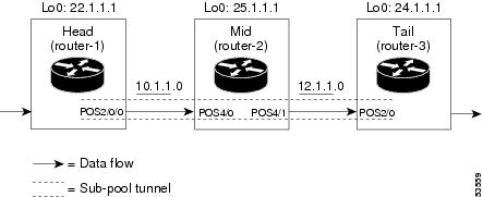
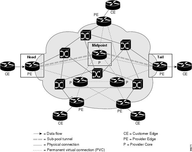
Sample topologies when the tunnel will run over ATM-PVCs are shown in the next two figures below.
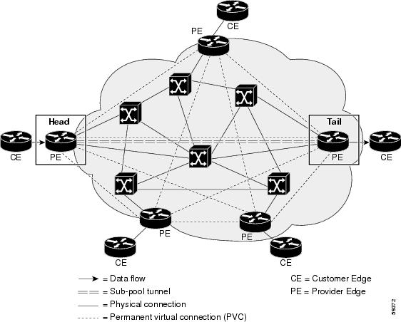
The full mesh topology shows no Midpoint device because the sub-pool tunnel can be routed along a direct PVC connecting the Head and Tail devices. However, if that particular PVC does not contain enough bandwidth, the tunnel can pass through alternate PVCs which may connect one or more PE routers. In that case the alternate PE router(s) will function as tunnel midpoint(s), and must be configured as shown in the Midpoint sections of the following configuration examples.
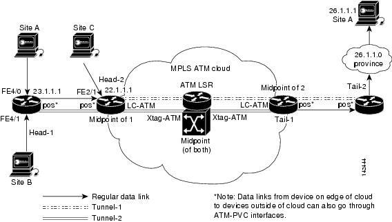
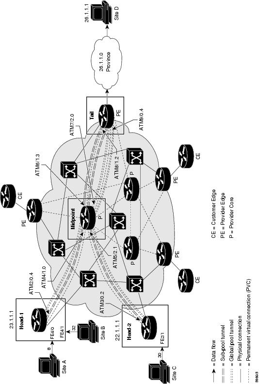
As shown in the figure below, DS-TE tunnels that travel through an MPLS ATM cloud can start either at a device outside the cloud or at one located on the edge of the cloud. Likewise, these tunnels can end either at a device on the edge of the cloud or one that is wholly outside the cloud. However, DS-TE tunnels cannot begin or end inside an MPLS ATM cloud.
On the edge of the cloud, the interface conveying the tunnel is an LC-ATM. Within the cloud, it is an XTag-ATM, residing on an ATM-LSR device.
A sample topology for tunnels that traverse LC-ATM interfaces is shown in the figure below
The following example refers to all three figures. Where the language is specific to only one type of interface, that fact is indicated.
- Tunnel Head
- Midpoint Devices
- Tail-End Device
- Guaranteed Bandwidth Service Configuration
- Guaranteed Bandwidth Service Examples
- Example with Single Destination Prefix
- Example with Many Destination Prefixes
Tunnel Head
At the device level:
router# configure terminal
Enter configuration commands, one per line.  End with CNTL/Z.
router(config)# ip cef
router(config)# mpls traffic-eng tunnels
[now one uses either the IS-IS commands on the left or the OSPF commands on the right]:
router(config)# router isis |
router ospf 100 |
router(config-router)# net 49.0000.1000.0000.0010.00 |
redistribute connected |
router(config-router)# metric-style wide |
network 10.1.1.0 0.0.0.255 area 0 |
router(config-router)# is-type level-1 |
network 22.1.1.1 0.0.0.0 area 0 |
router(config-router)# mpls traffic-eng level-1 |
mpls traffic-eng area 0 |
router(config-router)# passive-interface Loopback0 |
[now one resumes the common command set]:
router(config-router)# mpls traffic-eng router-id Loopback0
router(config-router)# exit
router(config)# interface Loopback0
At the virtual interface level:
router(config-if)# ip address 22.1.1.1 255.255.255.255
router(config-if)# no ip directed-broadcast
router(config-if)# exit
At the device level: [ATM cases appear on the left; POS case on the right]:
router(config)# interface atm3/0 |
interface POS2/0/0 |
[continuing each case at the network interface level (egress)]:
router(config-if)# mpls traffic-eng tunnels |
ip address 10.1.1.1 255.255.255.0 |
router(config-if)# ip rsvp bandwidth 130000 130000/ sub-pool 80000 |
mpls traffic-eng tunnels |
router(config-if)# interface atm3/0.5 [append the keyword mpls if LC-ATM] |
ip rsvp bandwidth 130000 130000/ sub-pool 80000 |
router(config-subif)# ip address 10.1.1.1 255.255.255.0 |
|
router(config-subif)#ip rsvp bandwidth 130000 130000 sub-pool 80000 |
|
router(config-subif)# mpls traffic-eng tunnels |
|
router(config-subif)# [if ATM-PVC]: atm pvc 10 10 100 aal5snap [if LC-ATM]: mpls atm vpi 2-5 |
|
[if using IS-IS instead of OSPF]: |
|
router(config-subif)# ip router isis |
|
router(config-subif)# exit |
|
router(config-if)# |
[If using IS-IS instead of OSPF]: ip router isis |
Continuing at the network interface level, regardless of interface type:
router(config-if)# exit
At the device level:
router(config)# interface Tunnel1
At the tunnel interface level:
router(config-if)# bandwidth 110000
router(config-if)# ip unnumbered Loopback0
router(config-if)# tunnel destination 24.1.1.1
router(config-if)# tunnel mode mpls traffic-eng
router(config-if)# tunnel mpls traffic-eng priority 0 0
router(config-if)# tunnel mpls traffic-eng bandwidth sub-pool 30000
router(config-if)# tunnel mpls traffic-eng path-option 1 dynamic
router(config-if)# exit
router(config)#
Midpoint Devices
At the device level:
router# configure terminal
router(config)# ip cef
router(config)# mpls traffic-eng tunnels
[now one uses either the IS-IS commands on the left or the OSPF commands on the right]:
router(config)# router isis |
router ospf 100 |
router(config-router)# net 49.0000.1000.0000.0012.00 |
redistribute connected |
router(config-router)# metric-style wide |
network 11.1.1.0 0.0.0.255 area 0 |
router(config-router)# is-type level-1 |
network 12.1.1.0 0.0.0.255 area 0 |
router(config-router)# mpls traffic-eng level-1 |
network 25.1.1.1 0.0.0.0 area 0 |
router(config-router)# passive-interface Loopback0 |
mpls traffic-eng area 0 |
[now one resumes the common command set]:
router(config-router)# mpls traffic-eng router-id Loopback0
router(config-router)# exit
router(config)# interface Loopback0
At the virtual interface level:
router(config-if)# ip address 25.1.1.1 255.255.255.255
router(config-if)# no ip directed-broadcast
router(config-if)# exit
[And if the device is an ATM-LSR:
router(config)#interface atm9/0 0/0/0
router(config-if)# label-control-protocol vsi
router(config-if)# exit
router(config)#mpls traffic-eng atm cos sub-pool
 ]
On all devices, for the ingress interface: [ATM-LSR appears on the left; ATM-PVC and LC-ATM cases in the middle; POS on the right]
router(config)# interface Xtagatm22
|
interface atm3/0
|
interface POS4/0
|
[continuing each case at the network interface level]
router(config-if)# extended-port atm9/0 bpx2.2 |
mpls traffic-eng tunnels
|
ip address 11.1.1.2 255.255.255.0 |
router(config-if)# ip address 11.1.1.2 255.255.255.0 |
ip rsvp bandwidth 130000 130000/ sub-pool 80000 |
mpls traffic-eng tunnels
|
router(config-if)# ip rsvp bandwidth 130000 130000 sub-pool 80000 |
ip rsvp bandwidth 130000 130000/ sub-pool 80000
|
|
router(config-if)# mpls traffic-eng tunnels |
[If using IS-IS instead of OSPF]:
ip router isis
|
|
router(config-if)# mpls atm vpi 2-15 |
||
router(config-if)# ip rsvp isis [only if using IS-IS instead of OSPF] |
interface atm3/0.5 [append the keyword mpls if LC-ATM] |
|
router(config-subif)# |
ip address 11.1.1.2 255.255.255.0
|
|
router(config-subif)# |
ip rsvp bandwidth 130000 130000 sub-pool 80000
|
|
router(config-subif)# |
mpls traffic-eng tunnels
|
|
router(config-subif)# |
[if ATM-PVC]: atm pvc 10 10 100 aal5snap [or if LC-ATM]: mpls atm vpi 2-15 |
|
router(config-subif)# |
[If using IS-IS instead of OSPF]:
ip router isis
|
|
router(config-subif)# |
exit
|
Continuing at the network interface level, regardless of interface type:
router(config-if)# exit
At the device level, for the egress interface: [ATM-LSR appears on the left; ATM-PVC and LC-ATM cases in the middle; POS on the right]
router(config)# interface Xtagatm44
|
interface atm4/0
|
interface POS4/1
|
[continuing each case at the network interface level]
router(config-if)# extended-port atm9/0 bpx4.4 |
mpls traffic-eng tunnels
|
ip address 12.1.1.2 255.255.255.0 |
router(config-if)# ip address 12.1.1.2 255.255.255.0 |
ip rsvp bandwidth 130000 130000/ sub-pool 80000 |
mpls traffic-eng tunnels
|
router(config-if)# ip rsvp bandwidth 130000 130000 sub-pool 80000 |
ip rsvp bandwidth 130000 130000/ sub-pool 80000
|
|
router(config-if)# mpls traffic-eng tunnels |
[If using IS-IS instead of OSPF]:
ip router isis
|
|
router(config-if)# mpls atm vpi 2-15 |
||
router(config-if)# ip router isis [only if using IS-IS instead of OSPF] |
interface atm4/0.5 [append the keyword mpls if LC-ATM] |
|
router(config-subif)# |
ip address 12.1.1.2 255.255.255.0
|
|
router(config-subif)# |
ip rsvp bandwidth 130000 130000 sub-pool 80000
|
|
router(config-subif)# |
mpls traffic-eng tunnels
|
|
router(config-subif)# |
[if ATM-PVC]: atm pvc 10 10 100 aal5snap [or if LC-ATM]: mpls atm vpi 2-15 |
|
router(config-subif)# |
[If using IS-IS instead of OSPF]:
ip router isis
|
|
router(config-subif)# |
exit
|
Continuing at the network interface level, regardless of interface type:
router(config-if)# exit
Note that there is no configuring of tunnel interfaces at the mid-point devices, only network interfaces, sub-interfaces, and the device globally.
When the midpoint device is an ATM-LSR, the following commands are also required. They are entered directly into the switch device, bypassing Cisco IOS:
BPX-12# uptrk 1.1
BPX-12# addshelf 1.1 v l.1
BPX-12# cnfrsrc
 1.1 256 252207 y 1 e 512 6144 2 15 26000 100000
BPX-12# uptrk 2.2
BPX-12# cnfrsrc
 2.2 256 252207 y 1 e 512 4096 2 5 26000 100000
BPX-12# uptrk 3.3
BPX-12# cnfrsrc
 3.3 256 252207 y 1 e 512 4096 2 5 26000 100000
BPX-12# uptrk 4.4
BPX-12# cnfrsrc
 4.4 256 252207 y 1 e 512 4096 2 5 26000 100000
BPX-12# uptrk 5.5
BPX-12# cnfrsrc
 5.5 256 252207 y 1 e 512 4096 2 5 26000 100000
Tail-End Device
At the device level:
router# configure terminal
router(config)# ip cef
router(config)# mpls traffic-eng tunnels
[now one uses either the IS-IS commands on the left or the OSPF commands on the right]:
router(config)# router isis |
router ospf 100 |
router(config-router)# net 49.0000.1000.0000.0013.00 |
redistribute connected |
router(config-router)# metric-style wide |
network 12.1.1.0 0.0.0.255 area 0 |
router(config-router)# is-type level-1 |
network 24.1.1.1 0.0.0.0 area 0 |
router(config-router)# mpls traffic-eng level-1 |
mpls traffic-eng area 0 |
router(config-router)# passive-interface Loopback0 |
[now one resumes the common command set]:
router(config-router)# mpls traffic-eng router-id Loopback0
router(config-router)# exit
router(config)# interface Loopback0
At the virtual interface level:
router(config-if)# ip address 24.1.1.1 255.255.255.255
router(config-if)# no ip directed-broadcast
[and if using IS-IS instead of OSPF]:
router(config-if)# ip router isis
[and in all cases]:
router(config-if)# exit
At the device level: [ATM cases appear on the left; POS case on the right]:
router(config)# interface atm2/0 |
interface POS2/0/0 |
[continuing each case at the network interface level (ingress)]:
router(config-if)# mpls traffic-eng tunnels |
ip address 12.1.1.3 255.255.255.0 |
router(config-if)# ip rsvp bandwidth 130000 130000/ sub-pool 80000 |
mpls traffic-eng tunnels |
router(config-if)# interface atm2/0.4 [append the keyword mpls if LC-ATM] |
ip rsvp bandwidth 130000 130000/ sub-pool 80000 |
router(config-subif)# ip address 12.1.1.3 255.255.255.0 |
|
router(config-subif)#ip rsvp bandwidth 130000 130000 sub-pool 80000 |
|
router(config-subif)# mpls traffic-eng tunnels |
|
router(config-subif)# [if ATM-PVC]: atm pvc 10 10 100 aal5snap [if LC-ATM]: mpls atm vpi 2-5 |
|
[if using IS-IS instead of OSPF]: |
|
router(config-subif)# ip router isis |
|
router(config-subif)# exit |
|
router(config-if)# |
[If using IS-IS instead of OSPF]: ip router isis |
Continuing at the network interface level, regardless of interface type:
router(config-if)# exit
Guaranteed Bandwidth Service Configuration
Having configured two bandwidth pools, you now can
Use one pool, the sub-pool, for tunnels that carry traffic requiring strict bandwidth guarantees or delay guarantees
Use the other pool, the global pool, for tunnels that carry traffic requiring only Differentiated Service.
Having a separate pool for traffic requiring strict guarantees allows you to limit the amount of such traffic admitted on any given link. Often, it is possible to achieve strict QoS guarantees only if the amount of guaranteed traffic is limited to a portion of the total link bandwidth.
Having a separate pool for other traffic (best-effort or diffserv traffic) allows you to have a separate limit for the amount of such traffic admitted on any given link. This is useful because it allows you to fill up links with best-effort/diffserv traffic, thereby achieving a greater utilization of those links.
- Providing Strict QoS Guarantees Using DS-TE Sub-pool Tunnels
- Providing Differentiated Service Using DS-TE Global Pool Tunnels
- Providing Strict Guarantees and Differentiated Service in the Same Network
Providing Strict QoS Guarantees Using DS-TE Sub-pool Tunnels
A tunnel using sub-pool bandwidth can satisfy the stricter requirements if you do all of the following:
Select a queue--or in diffserv terminology, select a PHB (per-hop behavior)--to be used exclusively by the strict guarantee traffic. This shall be called the "GB queue."
If delay/jitter guarantees are sought, the diffserv Expedited Forwarding queue (EF PHB) is used. On the Cisco 7200 it is the "priority" queue. You must configure the bandwidth of the queue to be at least equal to the bandwidth of the sub-pool.
If only bandwidth guarantees are sought, the diffserv Assured Forwarding PHB (AF PHB) is used. On the Cisco 7200 you use one of the existing Class-Based Weighted Fair Queuing (CBWFQ) queues.
Ensure that the guaranteed traffic sent through the sub-pool tunnel is placed in the GB queue at the outbound interface of every tunnel hop , and that no other traffic is placed in this queue.
You do this by marking the traffic that enters the tunnel with a unique value in the mpls exp bits field, and steering only traffic with that marking into the GB queue.
Ensure that this GB queue is never oversubscribed; that is, see that no more traffic is sent into the sub-pool tunnel than the GB queue can handle.
You do this by rate-limiting the guaranteed traffic before it enters the sub-pool tunnel. The aggregate rate of all traffic entering the sub-pool tunnel should be less than or equal to the bandwidth capacity of the sub-pool tunnel. Excess traffic can be dropped (in the case of delay/jitter guarantees) or can be marked differently for preferential discard (in the case of bandwidth guarantees).
Ensure that the amount of traffic entering the GB queue is limited to an appropriate percentage of the total bandwidth of the corresponding outbound link. The exact percentage to use depends on several factors that can contribute to accumulated delay in your network: your QoS performance objective, the total number of tunnel hops, the amount of link fan-in along the tunnel path, burstiness of the input traffic, and so on.
You do this by setting the sub-pool bandwidth of each outbound link to the appropriate percentage of the total link bandwidth (that is, by adjusting the z parameter of the ip rsvp bandwidth command).
Providing Differentiated Service Using DS-TE Global Pool Tunnels
You can configure a tunnel using global pool bandwidth to carry best-effort as well as several other classes of traffic. Traffic from each class can receive differentiated service if you do all of the following:
Select a separate queue (a distinct diffserv PHB) for each traffic class. For example, if there are three classes (gold, silver, and bronze) there must be three queues (diffserv AF2, AF3, and AF4). [If the tunnel is to cross an MPLS ATM cloud, only one class of global pool traffic may be configured.]
Mark each class of traffic using a unique value in the MPLS experimental bits field (for example gold = 4, silver = 5, bronze = 6). [On the ATM-LSR, you specify the class of service desired --premium, standard, or the default service, available--using the command mpls traffic-eng atm cos global-pool].
Ensure that packets marked as Gold are placed in the gold queue, Silver in the silver queue, and so on. The tunnel bandwidth is set based on the expected aggregate traffic across all classes of service.
To control the amount of diffserv tunnel traffic you intend to support on a given link, adjust the size of the global pool on that link.
Providing Strict Guarantees and Differentiated Service in the Same Network
Because DS-TE allows simultaneous constraint-based routing of sub-pool and global pool tunnels, strict guarantees and diffserv can be supported simultaneously in a given network.
Guaranteed Bandwidth Service Examples
Given the many topologies in which Guaranteed Bandwidth Services can be applied, there is space here only to present two examples. They illustrate opposite ends of the spectrum of possibilities.
In the first example, the guaranteed bandwidth tunnel can be easily specified by its destination. So the forwarding criteria refer to a single destination prefix.
In the second example, there can be many final destinations for the guaranteed bandwidth traffic, including a dynamically changing number of destination prefixes. So the forwarding criteria are specified by Border Gateway Protocol (BGP) policies.
Example with Single Destination Prefix
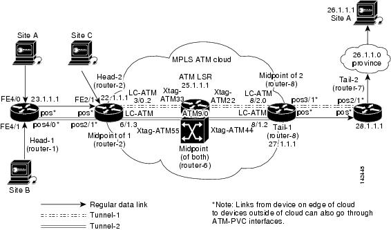
The three figures below illustrate topologies for guaranteed bandwidth services whose destination is specified by a single prefix. In the first figure below, the interfaces to be configured are POS (Packet over SONET), while in second figure below the interfaces are ATM-PVC (Asynchronous Transfer Mode - Permanent Virtual Circuit), and in the third figure below, they are LC-ATM (Label Controlled - Asynchronous Transfer Mode) and, within the MPLS ATM cloud, XTag-ATM. In all three illustrations, the destination for the guaranteed bandwidth service is either a single host (like a voice gateway, here designated "Site D" and bearing prefix 26.1.1.1) or a subnet (like a web farm, here called "Province" and bearing prefix 26.1.1.0). Three services are offered in each sample topology:
From Site A (defined as all traffic arriving at interface FE4/0): to host 26.1.1.1, 8 Mbps of guaranteed bandwidth with low loss, low delay and low jitter
From Site B (defined as all traffic arriving at interface FE4/1): towards subnet 26.1.1.0, 32 Mbps of guaranteed bandwidth with low loss
From Site C (defined as all traffic arriving at interface FE2/1): towards subnet 26.1.1.0, 30 Mbps of guaranteed bandwidth with low loss.
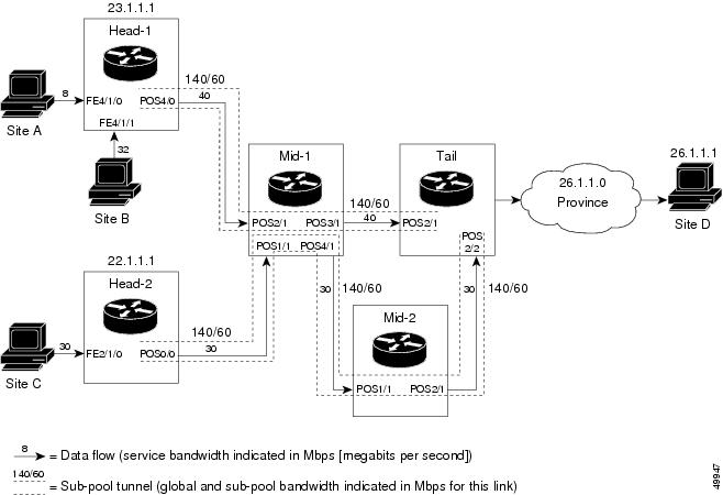
These three services run through two sub-pool tunnels:
From the Head-1 router, 23.1.1.1, to the router-4 tail (in our LC-ATM example, to tail router-8)
From the Head-2 router, 22.1.1.1, to the router-4 tail (in our LC-ATM example, to tail router-7)
In the POS and ATM-PVC examples, both tunnels use the same tail router, though they have different heads. This is to illustrate that many combinations are possible. (In Figure 5 one midpoint router is shared by both tunnels. In the real world there could of course be many more midpoints.)
All POS, ATM-PVC, LC-ATM, and XTagATM interfaces in this example are OC3, whose capacity is 155 Mbps.
- Configuring Tunnel Head-1
- Configuring Tunnel Head-2
- Tunnel Midpoint Configurations
- Tunnel Midpoint Configuration POS ingress and LC-ATM egress
- Tunnel Midpoint Configuration all POS
- Tunnel Midpoint Configurationz all XTag-ATM
- Tunnel Midpoint Configuration LC-ATM Ingress
- Tunnel Tail Configuration
Configuring Tunnel Head-1
First we recapitulate commands that establish two bandwidth pools and a sub-pool tunnel (as presented earlier on page 14). Then we present the QoS commands that guarantee end-to-end service on the subpool tunnel. With the 7200 router, Modular QoS CLI is used.
- Configuring the Pools and Tunnel
- For Service from Site A to Site D
- For Service from Site B to Subnet Province
- For Both Services
Configuring the Pools and Tunnel
At the device level:
router-1(config)# ip cef
router-1(config)# mpls traffic-eng tunnels
[now one uses either the IS-IS commands on the left or the OSPF commands on the right]:
router-1(config)# router isis |
router ospf 100 |
router-1(config-router)# net 49.0000.1000.0000.0010.00 |
redistribute connected |
router-1(config-router)# metric-style wide |
network 10.1.1.0 0.0.0.255 area 0 |
router-1(config-router)# is-type level-1 |
network 23.1.1.1 0.0.0.0 area 0 |
router-1(config-router)# mpls traffic-eng level-1 |
mpls traffic-eng area 0 |
router-1(config-router)# passive-interface Loopback0 |
[now one resumes the common command set]:
router-1(config-router)# mpls traffic-eng router-id Loopback0
router-1(config-router)# exit
Create a virtual interface:
router-1(config)# interface Loopback0
router-1(config-if)# ip address 23.1.1.1 255.255.255.255
router-1(config-if)# no ip directed-broadcast
router-1(config-if)# exit
For the outgoing network interface:
[ATM-PVC case appears on the left; POS case on the right]:
router-1(config)# interface atm2/0 |
interface POS4/0 |
[then continue each case at the network interface level:
router-1(config-if)# mpls traffic-eng tunnels |
ip address 10.1.1.1 255.255.255.0 |
router-1(config-if)# ip rsvp bandwidth 140000 140000\ sub-pool 60000 |
mpls traffic-eng tunnels |
router-1(config-if)# interface atm2/0.4 |
ip rsvp bandwidth 140000 140000\ sub-pool 60000 |
router-1(config-subif)# ip address 10.1.1.1 255.255.255.0 |
|
router-1(config-subif)#ip rsvp bandwidth 140000 140000\ sub-pool 60000 |
|
router-1(config-subif)# mpls traffic-eng tunnels |
|
router-1(config-subif)# atm pvc 10 10 100 aal5snap |
|
[if using IS-IS instead of OSPF]: |
|
router-1(config-subif)# ip router isis |
|
router-1(config-subif)# exit |
|
router-1(config-if)# |
[If using IS-IS instead of OSPF]: ip router isis |
Continuing at the network interface level, regardless of interface type:
router-1(config-if)# exit
At the tunnel interface:
router-1(config)# interface Tunnel1
router-1(config-if)# bandwidth 110000
router-1(config-if)# ip unnumbered Loopback0
router-1(config-if)# tunnel destination 27.1.1.1
router-1(config-if)# tunnel mode mpls traffic-eng
router-1(config-if)# tunnel mpls traffic-eng priority 0 0
router-1(config-if)# tunnel mpls traffic-eng bandwidth sub-pool 40000
router-1(config-if)# tunnel mpls traffic-eng path-option 1 dynamic
To ensure that packets destined to host 26.1.1.1 and subnet 26.1.1.0 are sent into the sub-pool tunnel, we create a static route. At the device level:
router-1(config)# ip route 26.1.1.0 255.255.255.0 Tunnel1
router-1(config)# exit
And in order to make sure that the Interior Gateway Protocol (IGP) will not send any other traffic down this tunnel, we disable autoroute announce:
router-1(config)# no tunnel mpls traffic-eng autoroute announce
For Service from Site A to Site D
At the inbound network interface (FE4/0):
1. In global configuration mode, create a class of traffic matching ACL 100, called "sla-1-class":
2. Create an ACL 100 to refer to all packets destined to 26.1.1.1:
3. Create a policy named "sla-1-input-policy", and according to that policy:
4. The policy is applied to packets entering interface FE4/0.
DETAILED STEPS
For Service from Site B to Subnet Province
At the inbound network interface (FE4/1):
1. In global configuration mode, create a class of traffic matching ACL 120, called "sla-2-class":
2. Create an ACL, 120, to refer to all packets destined to subnet 26.1.1.0:
3. Create a policy named "sla-2-input-policy", and according to that policy
4. The policy is applied to packets entering interface FE4/1.
DETAILED STEPS
For Both Services
The outbound interface (POS4/0 in Figure 5 and Figure 7, and ATM2/0.4 in Figure 6) is configured as follows:
1. In global configuration mode, create a class of traffic matching experimental bit 5, called "exp-5-traffic".
2. Create a policy named "output-interface-policy". According to that policy, packets in the class "exp-5-traffic" are put in the priority queue (which is rate-limited to 62 kbits/sec).
3. The policy is applied to packets exiting subinterface ATM2/0.4 (first example) or interface POS4/0 (second example):
DETAILED STEPS
| Step 1 |
In global configuration mode, create a class of traffic matching experimental bit 5, called "exp-5-traffic". Example: class-map match-all exp-5-traffic match mpls experimental 5 |
| Step 2 |
Create a policy named "output-interface-policy". According to that policy, packets in the class "exp-5-traffic" are put in the priority queue (which is rate-limited to 62 kbits/sec). Example: policy-map output-interface-policy class exp-5-traffic priority 62 |
| Step 3 |
The policy is applied to packets exiting subinterface ATM2/0.4 (first example) or interface POS4/0 (second example): Example: interface atm2/0 interface atm2/0.4 service-policy output output-interface-policy
Example: interface POS4/0 service-policy output\ output-interface-policy The result of the above configuration lines is that packets entering the router via interface FE4/0 destined to host 26.1.1.1, or entering the router via interface FE4/1 destined to subnet 26.1.1.0, will have their MPLS experimental bit set to 5. We assume that no other packets entering the router (on any interface) are using this value. (If this cannot be assumed, an additional configuration must be added to mark all such packets to another experimental value.) Packets marked with experimental bit 5, when exiting the router via interface POS4/0 or subinterface ATM2/0.4, will be placed into the priority queue. |
Configuring Tunnel Head-2
First we recapitulate commands that establish two bandwidth pools and a sub-pool tunnel (as presented earlier on page 16). Then we present the QoS commands that guarantee end-to-end service on the subpool tunnel. With the 7200 router, Modular QoS CLI is used. [And because this router is on the edge of the MPLS ATM cloud in Figure 7, an LC-ATM interface is configured in that example.]
Configuring the Pools and Tunnel
At the device level:
router-2(config)# ip cef
router-2(config)# mpls traffic-eng tunnels
[now one uses either the IS-IS commands on the left or the OSPF commands on the right]:
router-2(config)# router isis |
router ospf 100 |
router-2(config-router)# net 49.0000.1000.0000.0011.00 |
redistribute connected |
router-2(config-router)# metric-style wide |
network 11.1.1.0 0.0.0.255 area 0 |
router-2(config-router)# is-type level-1 |
network 22.1.1.1 0.0.0.0 area 0 |
router-2(config-router)# mpls traffic-eng level-1 |
mpls traffic-eng area 0 |
router-2(config-router)# passive-interface Loopback0 |
[now one resumes the common command set]:
router-2(config-router)# mpls traffic-eng router-id Loopback0
router-2(config-router)# exit
Create a virtual interface:
router-2(config)# interface Loopback0
router-2(config-if)# ip address 22.1.1.1 255.255.255.255
router-2(config-if)# no ip directed-broadcast
router-2(config-if)# exit
For the outgoing network interface:
[ATM cases appear on the left; POS case on the right]:
router-2(config)# interface atm3/0 |
interface POS0/0 |
[then continue each case at the network interface level]:
router-2(config-if)# mpls traffic-eng tunnels |
ip address 11.1.1.1 255.0.0.0 |
router-2(config-if)# ip rsvp bandwidth 140000 140000\ sub-pool 60000 |
mpls traffic-eng tunnels |
router-2(config-if)# interface atm3/0.2 [append the keyword mpls if LC-ATM] |
ip rsvp bandwidth 140000 140000\ sub-pool 60000 |
router-2(config-subif)# ip address 11.1.1.1 255.0.0.0 |
|
router-2(config-subif)#ip rsvp bandwidth 140000 140000 sub-pool 60000 |
|
router-2(config-subif)# mpls traffic-eng tunnels |
|
router-2(config-subif)# [if ATM-PVC]: atm pvc 10 10 100 aal5snap [if LC-ATM]: mpls atm vpi 2-5 |
|
[if using IS-IS instead of OSPF]: |
|
router-2(config-subif)# ip router isis |
|
router-2(config-subif)# exit |
|
router-2(config-if)# |
[If using IS-IS instead of OSPF]: ip router isis |
Continuing at the network interface level, regardless of interface type:
router-2(config-if)# exit
At the tunnel interface:
router-2(config)# interface Tunnel2
router-2(config-if)# ip unnumbered Loopback0
router-2(config-if)# tunnel destination 27.1.1.1

[though in Figure 7:
tunnel destination 28.1.1.1
]
router-2(config-if)# tunnel mode mpls traffic-eng
router-2(config-if)# tunnel mpls traffic-eng priority 0 0
router-2(config-if)# tunnel mpls traffic-eng bandwidth sub-pool 30000
router-2(config-if)# tunnel mpls traffic-eng path-option 1 dynamic
To ensure that packets destined to subnet 26.1.1.0 are sent into the sub-pool tunnel, we create a static route. At the device level:
router-2(config)# ip route 26.1.1.0 255.255.255.0 Tunnel2
router-2(config)# exit
And in order to make sure that the Interior Gateway Protocol (IGP) will not send any other traffic down this tunnel, we disable autoroute announce:
router-2(config)# no tunnel mpls traffic-eng autoroute announce
For Service from Site C to Subnet Province
At the inbound network interface (FE2/1):
1. In global configuration mode, create a class of traffic matching ACL 130, called "sla-3-class":
2. Create an ACL, 130, to refer to all packets destined to subnet 26.1.1.0:
3. Create a policy named "sla-3-input-policy", and according to that policy:
4. The policy is applied to packets entering interface FE2/1.
5. The outbound interface (POS0/0 or ATM3/0.2) is configured as follows:
6. In global configuration mode, create a class of traffic matching experimental bit 5, called "exp-5-traffic".
7. Create a policy named "output-interface-policy". According to that policy, packets in the class "exp-5-traffic" are put in the priority queue (which is rate-limited to 32 kbits/sec).
8. The policy is applied to packets exiting interface ATM3/0.2 (first example) or POS0/0 (second example):
DETAILED STEPS
Tunnel Midpoint Configurations
All four interfaces on the 7200 midpoint router ("Mid-1" in Figure 5, "Midpoint" in Figure 6) are configured identically to the outbound interface of the head router (except, of course, for the IDs of the individual interfaces).
When an ATM-LSR serves as a midpoint (as in Figure 7), its XTagATM interfaces and BPX or IGX switching resources must be configured. Also, two new MPLS commands are used. The details of this configuration are presented in the ATM-LSR section which begins on page 38.
The LC-ATM midpoint configuration (on the left edge of the ATM cloud in Figure 7) is presented on page 35. LC-ATM at a midpoint on the right edge of the cloud in Figure 7 is presented on page 39.
Configuring the Pools and Tunnels
At the device level:
router-3(config)# ip cef
router-3(config)# mpls traffic-eng tunnels
[now one uses either the IS-IS commands on the left or the OSPF commands on the right]:
router-3(config)# router isis |
router ospf 100 |
router-3(config-router)# net 49.0000.2400.0000.0011.00 |
redistribute connected |
router-3(config-router)# metric-style wide |
network 10.1.1.0 0.0.0.255 area 0 |
router-3(config-router)# is-type level-1 |
network 11.1.1.0 0.0.0.255 area 0 |
router-3(config-router)# mpls traffic-eng level-1 |
network 24.1.1.1 0.0.0.0 area 0 |
router-3(config-router)# passive-interface Loopback0 |
network 12.1.1.0 0.0.0.255 area 0 |
router-3(config-router)# |
network 13.1.1.0 0.0.0.255 area 0 |
router-3(config-router)# |
mpls traffic-eng area 0 |
[now one resumes the common command set]:
router-3(config-router)# mpls traffic-eng router-id Loopback0
router-3(config-router)# exit
Create a virtual interface:
router-3(config)# interface Loopback0
router-3(config-if)# ip address 22.1.1.1 255.255.255.255
router-3(config-if)# exit
For one incoming network interface, first at the device level:
[ATM-PVC case appears on the left; POS case on the right]:
router-3(config)# interface atm4/1 |
interface POS2/1 |
[then continue each case at the network interface level]:
router-3(config-if)# mpls traffic-eng tunnels |
ip address 10.1.1.2 255.0.0.0 |
router-3(config-if)# ip rsvp bandwidth 140000 140000\ sub-pool 60000 |
mpls traffic-eng tunnels |
router-3(config-if)# interface atm4/1.0 |
ip rsvp bandwidth 140000 140000\ sub-pool 60000 |
router-3(config-subif)# ip address 10.1.1.2 255.0.0.0 |
|
router-3(config-subif)#ip rsvp bandwidth 140000 140000 sub-pool 60000 |
|
router-3(config-subif)# mpls traffic-eng tunnels |
|
router-3(config-subif)# atm pvc 10 10 100 aal5snap |
|
[if using IS-IS instead of OSPF]: |
|
router-3(config-subif)# ip router isis |
|
router-3(config-subif)# exit |
|
router-3(config-if)# |
[If using IS-IS instead of OSPF]: ip router isis |
Continuing at the network interface level, regardless of interface type:
router-3(config-if)# exit
For the other incoming network interface, first at the device level:
[ATM-PVC case appears on the left; POS case on the right]:
router-3(config)# interface atm5/2 |
interface POS1/1 |
[then continuing each case at the network interface level]:
router-3(config-if)# mpls traffic-eng tunnels |
ip address 11.1.1.2 255.0.0.0 |
router-3(config-if)# ip rsvp bandwidth 140000 140000/ sub-pool 60000 |
mpls traffic-eng tunnels |
router-3(config-if)# interface atm5/2.1 |
ip rsvp bandwidth 140000 140000/ sub-pool 60000 |
router-3(config-subif)# ip address 11.1.1.2 255.0.0.0 |
|
router-3(config-subif)#ip rsvp bandwidth 140000 140000\ sub-pool 60000 |
|
router-3(config-subif)# mpls traffic-eng tunnels |
|
router-3(config-subif)# atm pvc 10 10 100 aal5snap |
|
[if using IS-IS instead of OSPF]: |
|
router-3(config-subif)# ip router isis |
|
router-3(config-subif)# exit |
|
router-3(config-if)# |
[If using IS-IS instead of OSPF]: ip router isis |
Continuing at the network interface level, regardless of interface type:
router-3(config-if)# exit
For one outgoing network interface:
[ATM-PVC case appears on the left; POS case on the right]:
router-3(config)# interface atm6/1 |
interface POS3/1 |
[then continue each case at the network interface level]:
router-3(config-if)# mpls traffic-eng tunnels |
ip address 11.1.1.2 255.0.0.0 |
router-3(config-if)# ip rsvp bandwidth 140000 140000\ sub-pool 60000 |
mpls traffic-eng tunnels |
router-3(config-if)# interface atm6/1.3 |
ip rsvp bandwidth 140000 140000\ sub-pool 60000 |
router-3(config-subif)# ip address 11.1.1.2 255.0.0.0 |
|
router-3(config-subif)#ip rsvp bandwidth 140000 140000\ sub-pool 60000 |
|
router-3(config-subif)# mpls traffic-eng tunnels |
|
router-3(config-subif)# atm pvc 10 10 100 aal5snap |
|
[if using IS-IS instead of OSPF]: |
|
router-3(config-subif)# ip router isis |
|
router-3(config-subif)# exit |
|
router-3(config-if)# |
[If using IS-IS instead of OSPF]: ip router isis |
Continuing at the network interface level, regardless of interface type:
router-3(config-if)# exit
For the other outgoing network interface, first at the device level:
[ATM-PVC case appears on the left; POS case on the right]:
router-3(config)# interface atm7/2 |
interface POS3/1 |
[then, continuing each case at the network interface level]:
router-3(config-if)# mpls traffic-eng tunnels |
ip address 12.1.1.1 255.0.0.0 |
router-3(config-if)# ip rsvp bandwidth 140000 140000\ sub-pool 60000 |
mpls traffic-eng tunnels |
router-3(config-if)# interface atm7/2.0 |
ip rsvp bandwidth 140000 140000\ sub-pool 60000 |
router-3(config-subif)# ip address 12.1.1.1 255.0.0.0 |
|
router-3(config-subif)#ip rsvp bandwidth 140000 140000\ sub-pool 60000 |
|
router-3(config-subif)# mpls traffic-eng tunnels |
|
router-3(config-subif)# atm pvc 10 10 100 aal5snap |
|
[if using IS-IS instead of OSPF]: |
|
router-3(config-subif)# ip router isis |
|
router-3(config-subif)# exit |
|
router-3(config-if)# |
[If using IS-IS instead of OSPF]: ip router isis |
Continuing at the network interface level, regardless of interface type:
router-3(config-if)# exit
Tunnel Midpoint Configuration POS ingress and LC-ATM egress
Configuring the Pools and Tunnels
At the device level:
router-2(config)# ip cef
router-2(config)# mpls traffic-eng tunnels
[now one uses either the IS-IS commands on the left or the OSPF commands on the right]:
router-2(config)# router isis |
router ospf 100 |
router-2(config-router)# net 49.0000.2400.0000.0011.00 |
redistribute connected |
router-2(config-router)# metric-style wide |
network 10.1.1.0 0.0.0.255 area 0 |
router-2(config-router)# is-type level-1 |
network 11.1.1.0 0.0.0.255 area 0 |
router-2(config-router)# mpls traffic-eng level-1 |
network 24.1.1.1 0.0.0.0 area 0 |
router-2(config-router)# passive-interface Loopback0 |
network 12.1.1.0 0.0.0.255 area 0 |
router-2(config-router)# |
network 13.1.1.0 0.0.0.255 area 0 |
router-2(config-router)# |
mpls traffic-eng area 0 |
[now one resumes the common command set]:
router-2(config-router)# mpls traffic-eng router-id Loopback0
router-2(config-router)# exit
Create a virtual interface:
router-2(config)# interface Loopback0
router-2(config-if)# ip address 22.1.1.1 255.255.255.255
router-2(config-if)# exit
For the incoming network interface, first at the device level:
router-2(config)# interface POS2/1
[then continuing at the network interface level]:
router-2(config-if)# ip address 11.1.1.2 255.0.0.0
router-2(config-if)# mpls traffic-eng tunnels
router-2(config-if)# ip rsvp bandwidth 140000 140000 sub-pool 60000
[If using IS-IS instead of OSPF]:
router-2(config-if)# ip router isis
[and in both cases]:
router-2(config-if)# exit
For the outgoing network interface:
router-2(config)# interface atm6/1
router-2(config-if)# mpls traffic-eng tunnels
router-2(config-if)# ip rsvp bandwidth 140000 140000 sub-pool 60000
router-2(config-if)# interface atm6/1.3 mpls
router-2(config-subif)# ip address 11.1.1.2 255.0.0.0
router-2(config-subif)#ip rsvp bandwidth 140000 140000 sub-pool 60000
router-2(config-subif)# mpls traffic-eng tunnels
router-2(config-subif)# mpls atm vpi 2-15
[if using IS-IS instead of OSPF]:
router-2(config-subif)# ip router isis
router-2(config-subif)# exit
[and in bothcases]:
router-2(config-if)# exit
Tunnel Midpoint Configuration all POS
[For the sake of simplicity, the ATM-PVC example (Figure 6) was illustrated with only one midpoint router.]
Both interfaces on the second 7200 midpoint router are configured identically to the outbound interface of the head router (except, of course, for the IDs of the individual interfaces):
Configuring the Pools and Tunnel
At the device level:
router-5(config)# ip cef
router-5(config)# mpls traffic-eng tunnels
[now one uses either the IS-IS commands on the left or the OSPF commands on the right]:
router-5(config)# router isis |
router ospf 100 |
router-5(config-router)# net 49.2500.1000.0000.0012.00 |
redistribute connected |
router-5(config-router)# metric-style wide |
network 13.1.1.0 0.0.0.255 area 0 |
router-5(config-router)# is-type level-1 |
network 14.1.1.0 0.0.0.255 area 0 |
router-5(config-router)# mpls traffic-eng level-1 |
network 25.1.1.1 0.0.0.0 area 0 |
router-5(config-router)# passive-interface Loopback0 |
mpls traffic-eng area 0 |
[now one resumes the common command set]:
router-5(config-router)# mpls traffic-eng router-id Loopback0
router-5(config-router)# exit
Create a virtual interface:
router-5(config)# interface Loopback0
router-5(config-if)# ip address 25.1.1.1 255.255.255.255
router-5(config-if)# exit
At the incoming network interface level:
router-5(config)# interface pos1/1
router-5(config-if)# ip address 13.1.1.2 255.0.0.0
router-5(config-if)# mpls traffic-eng tunnels
router-5(config-if)# ip rsvp bandwidth 140000 140000 sub-pool 60000
[and if using IS-IS instead of OSPF]:
router-5(config-if)# ip router isis
[and in all cases]:
router-5(config-if)# exit
At the outgoing network interface level:
router-5(config)# interface pos2/1
router-5(config-if)# ip address 14.1.1.1 255.0.0.0
router-5(config-if)# mpls traffic-eng tunnels
router-5(config-if)# ip rsvp bandwidth 140000 140000 sub-pool 60000
[and if using IS-IS instead of OSPF]:
router-5(config-if)# ip router isis
[and in all cases]:
router-5(config-if)# exit
Tunnel Midpoint Configurationz all XTag-ATM
When an ATM-LSR serves as a midpoint, its Virtual Switch Interface, XTagATM interfaces, and BPX or IGX switching resources must be configured. Also, one or two new MPLS commands are used on the ATM-LSR (namely, mpls traffic-eng atm cos sub-pool and mpls traffic-eng atm cos global-pool), to transfer traffic from priority queues into class-of-service (since the cell-based switch cannot examine packets).
Configuring the Pools and Tunnel
At the device level:
router-6(config)# ip cef
router-6(config)# mpls traffic-eng tunnels
[now one uses either the IS-IS commands on the left or the OSPF commands on the right]:
router-6(config)# router isis |
router ospf 100 |
router-6(config-router)# net 49.0000.2400.0000.0011.00 |
redistribute connected |
router-6(config-router)# metric-style wide |
network 10.1.1.0 0.0.0.255 area 0 |
router-6(config-router)# is-type level-1 |
network 11.1.1.0 0.0.0.255 area 0 |
router-6(config-router)# mpls traffic-eng level-1 |
network 24.1.1.1 0.0.0.0 area 0 |
router-6(config-router)# passive-interface Loopback0 |
network 12.1.1.0 0.0.0.255 area 0 |
router-6(config-router)# |
network 13.1.1.0 0.0.0.255 area 0 |
router-6(config-router)# |
mpls traffic-eng area 0 |
[now one resumes the common command set]:
router-6(config-router)# mpls traffic-eng router-id Loopback0
router-6(config-router)# exit
Create a virtual interface:
router-6(config)# interface Loopback0
router-6(config-if)# ip address 25.1.1.1 255.255.255.255
router-6(config-if)# exit
At the device level, to coordinate traffic across the router and switch portions of the device:
router-6(config)# interface atm9/0 0/0/0
router-6(config-if)# label-control-protocol vsi
router-6(config-if)# exit
router-6(config)# mpls traffic-eng atm cos sub-pool
router-6(config)# mpls traffic-eng atm cos global-pool premiun
For one incoming network interface:
router-6(config)# interface Xtagatm22
router-6(config-if)# extended-port atm9/0 bpx2.2
router-6(config-if)# ip address 10.1.1.2 255.0.0.0
router-6(config-if)# ip rsvp bandwidth 140000 140000 sub-pool 60000
router-6(config-if)# mpls traffic-eng tunnels
router-6(config-if)# mpls atm vpi 2-15
[If using IS-IS instead of OSPF]:
router-6(config-if)# ip router isis
[and in either case]:
router-6(config-if)# exit
For the other incoming network interface: router-6(config)# interface xtagatm55
router-6(config-if)# extended-port atm9/0 bpx5.5
router-6(config-if)# ip address 11.1.1.2 255.0.0.0
router-6(config-if)# ip rsvp bandwidth 140000 140000 sub-pool 60000
router-6(config-if)# mpls traffic-eng tunnels
router-6(config-if)# mpls atm vpi 2-15
[If using IS-IS instead of OSPF]:
router-6(config-if)# ip router isis
[and in either case]:
router-6(config-if)# exit
For one outgoing network interface: router-6(config)# interface Xtagatm33
router-6(config-if)# extended-port atm9/0 bpx3.3
router-6(config-if)# ip address 11.1.1.2 255.0.0.0
router-6(config-if)# ip rsvp bandwidth 140000 140000 sub-pool 60000
router-6(config-if)# mpls traffic-eng tunnels
router-6(config-if)# mpls atm vpi 2-15
[If using IS-IS instead of OSPF]:
router-6(config-if)# ip router isis
[and in either case]:
router-6(config-if)# exit
For the other outgoing network interface: router-6(config)# interface Xtagatm44
router-6(config-if)# extended-port atm9/0 bpx4.4
router-6(config-if)# ip address 12.1.1.1 255.0.0.0
router-6(config-if)# ip rsvp bandwidth 140000 140000 sub-pool 60000
router-6(config-if)# mpls traffic-eng tunnels
router-6(config-if)# mpls atm vpi 2-15
[If using IS-IS instead of OSPF]:
router-6(config-if)# ip router isis
[and in either case]:
router-6(config-if)# exit
Tunnel Midpoint Configuration LC-ATM Ingress
This 7200 midpoint router sits at the right-side edge of the MPLS ATM cloud in Figure 7. Therefore its ingress interface is LC-ATM and its egress can be either POS or ACM-PVC.
Configuring the Pools and Tunnels
At the device level:
router-8(config)# ip cef
router-8(config)# mpls traffic-eng tunnels
[now one uses either the IS-IS commands on the left or the OSPF commands on the right]:
router-8(config)# router isis |
router ospf 100 |
router-8(config-router)# net 49.2500.1000.0000.0012.00 |
redistribute connected |
router-8(config-router)# metric-style wide |
network 13.1.1.0 0.0.0.255 area 0 |
router-8(config-router)# is-type level-1 |
network 14.1.1.0 0.0.0.255 area 0 |
router-8(config-router)# mpls traffic-eng level-1 |
network 25.1.1.1 0.0.0.0 area 0 |
router-8(config-router)# passive-interface Loopback0 |
mpls traffic-eng area 0 |
[now one resumes the common command set]:
router-8(config-router)# mpls traffic-eng router-id Loopback0
router-8(config-router)# exit
Create a virtual interface:
router-8(config)# interface Loopback0
router-8(config-if)# ip address 27.1.1.1 255.255.255.255
router-8(config-if)# exit
At the incoming network interface level:
router-8(config)# interface atm8/2
router-8(config-if)# mpls traffic-eng tunnels
router-8(config-if)# ip rsvp bandwidth 140000 140000\ sub-pool 60000
router-8(config-if)# interface atm8/2.0 mpls
router-8(config-subif)# ip address 13.1.1.2 255.0.0.0
router-8(config-subif)# ip rsvp bandwidth 140000 140000 sub-pool 60000
router-8(config-subif)# mpls traffic-eng tunnels
router-8(config-subif)# mpls atm vpi 2-15
[if using IS-IS instead of OSPF]:
router-8(config-subif)# ip router isis
router-8(config-subif)# exit
And in all cases:
router-8(config-if)# exit
For the outgoing network interface:
[ATM-PVC case appears on the left; POS case on the right]:
router-8(config)# interface atm6/1 |
interface POS3/1 |
[then continue each case at the network interface level]:
router-8(config-if)# mpls traffic-eng tunnels |
ip address 14.1.1.1 255.0.0.0 |
router-8(config-if)# ip rsvp bandwidth 140000 140000\ sub-pool 60000 |
mpls traffic-eng tunnels |
router-8(config-if)# interface atm6/1.3 |
ip rsvp bandwidth 140000 140000\ sub-pool 60000 |
router-8(config-subif)# ip address 14.1.1.1 255.0.0.0 |
|
router-8(config-subif)#ip rsvp bandwidth 140000 140000\ sub-pool 60000 |
|
router-8(config-subif)# mpls traffic-eng tunnels |
|
router-8(config-subif)# atm pvc 10 10 100 aal5snap |
|
[if using IS-IS instead of OSPF]: |
|
router-8(config-subif)# ip router isis |
|
router-8(config-subif)# exit |
|
router-8(config-if)# |
[If using IS-IS instead of OSPF]: ip router isis |
Continuing at the network interface level, regardless of interface type:
router-8(config-if)# exit
Tunnel Tail Configuration
The inbound interfaces on the 7200 tail router are configured identically to the inbound interfaces of the midpoint routers (except, of course, for the ID of each particular interface):
Configuring the Pools and Tunnels
At the device level:
router-4-8-or-7(config)# ip cef
router-4-8-or-7(config)# mpls traffic-eng tunnels
[now one uses either the IS-IS commands on the left or the OSPF commands on the right]:
router-4-8-or-7(config)# router isis |
router ospf 100 |
router-4-8-or-7(config-router)# net 49.0000.2700.0000.0000.00 |
redistribute connected |
router-4-8-or-7(config-router)# metric-style wide |
network 12.1.1.0 0.0.0.255 area 0 |
router-4-8-or-7(config-router)# is-type level-1 |
network 14.1.1.0 0.0.0.255 area 0 |
router-4-8-or-7(config-router)# mpls traffic-eng level-1 |
network 27.1.1.1 0.0.0.0 area 0 |
router-4-8-or-7(config-router)# passive-interface Loopback0 |
mpls traffic-eng area 0 |
[now one resumes the common command set]:
router-4-8-or-7(config-router)# mpls traffic-eng router-id Loopback0
router-4-8-or-7(config-router)# exit
Create a virtual interface:
router-4-8-or-7(config)# interface Loopback0
router-4-8-or-7(config-if)# ip address 27.1.1.1 255.255.255.255
[but on router-7 in Figure 7 use ip address 28.1.1.1 255.255.255.255
]
router-4-8-or-7(config-if)# exit
For the incoming network interface, first at the device level:
[LC-ATM case appears on the left; POS case on the right]:
router-4-8-or-7(config)# interface atm8/1 |
interface POS2/1 |
[then continue each case at the network interface level]:
router-4-8-or-7(config-if)# mpls traffic-eng tunnels |
ip address 12.1.1.2 255.0.0.0 |
router-4-8-or-7(config-if)# ip rsvp bandwidth 140000\ 140000 sub-pool 60000 |
mpls traffic-eng tunnels |
router-4-8-or-7(config-if)# interface atm8/1.2 mpls |
ip rsvp bandwidth 140000 140000\ sub-pool 60000 |
router-4-8-or-7(config-subif)# ip address 12.1.1.2 255.0.0.0 |
|
router-4-8-or-7(config-subif)#ip rsvp bandwidth 140000\ 140000 sub-pool 60000 |
|
router-4-8-or-7(config-subif)# mpls traffic-eng tunnels |
|
router-4-8-or-7(config-subif)# mpls atm vpi 2-5 |
|
[if using IS-IS instead of OSPF]: |
|
router-4-8-or-7(config-subif)# ip router isis |
|
router-4-8-or-7(config-subif)# exit |
|
router-4-8-or-7(config-if)# |
[If using IS-IS instead of OSPF]: ip router isis |
Continuing at the network interface level, regardless of interface type:
router-4-8-or-7(config-if)# exit
Because the tunnel ends on the tail (does not include any outbound interfaces of the tail router), no outbound QoS configuration is used.
Example with Many Destination Prefixes
The two figures below illustrate topologies for guaranteed bandwidth services whose destinations are a set of prefixes. In the first figure below the interfaces to be configured are POS (Packet over SONET), while in second figure below the interfaces are ATM-PVC (Asynchronous Transfer Mode – Permanent Virtual Circuit). In both illustrations, the destinations’ prefixes usually share some common properties such as belonging to the same Autonomous System (AS) or transiting through the same AS. Although the individual prefixes may change dynamically because of route flaps in the downstream autonomous systems, the properties the prefixes share will not change. Policies addressing the destination prefix set are enforced through Border Gateway Protocol (BGP), which is described in the following documents:
"Configuring QoS Policy Propagation via Border Gateway Protocol" in the Cisco IOS Quality of Service Solutions Configuration Guide, Release 12.1 (http://www.cisco.com/univercd/cc/td/doc/product/software/ios121/121cgcr/qos_c/qcprt1/qcdprop.htm)
"Configuring BGP" in the Cisco IOS IP and IP Routing Configuration Guide, Release 12.1 (http://www.cisco.com/univercd/cc/td/doc/product/software/ios121/121cgcr/ip_c/ipcprt2/1cdbgp.htm)
"BGP Commands" in the Cisco IOS IP and IP Routing Command Reference, Release 12.1 (http://www.cisco.com/univercd/cc/td/doc/product/software/ios121/121cgcr/ip_r/iprprt2/1rdbgp.htm)
In this example, three guaranteed bandwidth services are offeref:
Traffic coming from Site A (defined as all traffic arriving at interface FE4/0) and from Site C (defined as all traffic arriving at interface FE2/1) destined to AS5
Traffic coming from Sites A and C that transits AS5 but is not destined to AS5. (In the figure, the transiting traffic will go to AS6 and AS7)
Traffic coming from Sites A and C destined to prefixes advertised with a particular BGP community attribute (100:1). In this example, Autonomous Systems #3, #5, and #8 are the BGP community assigned the attribute 100:1.
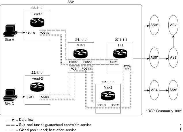

The applicability of guaranteed bandwidth service is not limited to the three types of multiple destination scenarios described above. There is not room in this document to present all possible scenarios. These three were chosen as representative of the wide range of possible deployments.
The guaranteed bandwidth services run through two sub-pool tunnels:
In addition, a global pool tunnel has been configured from each head end, to carry best-effort traffic to the same destinations. All four tunnels use the same tail router, even though they have different heads and differ in their passage through the midpoint(s). (Of course in the real world there would likely be many more midpoints than just the one or two shown here.)
All POS and ATM-PVC interfaces in this example are OC3, whose capacity is 155 Mbps.
Configuring a multi-destination guaranteed bandwidth service involves:
Building a sub-pool MPLS-TE tunnel
Configuring DiffServ QoS
Configuring QoS Policy Propagation via BGP (QPPB)
Mapping traffic onto the tunnels
All of these tasks are included in the following example.
- Tunnel Head Configuration Head-1
- Tunnel Head Configuration Head-2
- Tunnel Midpoint Configuration Mid-1
- Tunnel Midpoint Configuration Mid-2
- Tunnel Tail Configuration
Tunnel Head Configuration Head-1
First we recapitulate commands that establish a sub-pool tunnel (commands presented earlier on page 9) and now we also configure a global pool tunnel. Additionally, we present QoS and BGP commands that guarantee end-to-end service on the sub-pool tunnel. (With the 7200 router, Modular QoS CLI is used).
- Configuring the Pools and Tunnels
- Configuring DiffServ QoS
- Configuring QoS Policy Propagation via BGP
- For All GB Services
- For GB Service Destined to AS5
- For GB Service Transiting through AS5
- For GB Service Destined to Community 100:1
- Mapping Traffic onto the Tunnels
Configuring the Pools and Tunnels
At the device level:
router-1(config)# ip cef
router-1(config)# mpls traffic-eng tunnels
[now one uses either the IS-IS commands on the left or the OSPF commands on the right]:
router-1(config)# router isis |
router ospf 100 |
router-1(config-router)# net 49.0000.1000.0000.0010.00 |
redistribute connected |
router-1(config-router)# metric-style wide |
network 10.1.1.0 0.0.0.255 area 0 |
router-1(config-router)# is-type level-1 |
network 23.1.1.1 0.0.0.0 area 0 |
router-1(config-router)# mpls traffic-eng level-1 |
mpls traffic-eng area 0 |
[now one resumes the common command set]:
router-1(config-router)# mpls traffic-eng router-id Loopback0
router-1(config-router)# exit
Create a virtual interface:
router-1(config)# interface Loopback0
router-1(config-if)# ip address 23.1.1.1 255.255.255.255
router-1(config-if)# exit
For the outgoing network interface:
[ATM-PVC case appears on the left; POS case on the right]:
router-1(config)# interface atm2/0 |
interface POS4/0 |
[then continue each case at the network interface level:
router-1(config-if)# mpls traffic-eng tunnels |
ip address 10.1.1.1 255.0.0.0 |
router-1(config-if)# ip rsvp bandwidth 140000 140000\ sub-pool 60000 |
mpls traffic-eng tunnels |
router-1(config-if)# interface atm2/0.4 |
ip rsvp bandwidth 140000 140000\ sub-pool 60000 |
router-1(config-subif)# ip address 10.1.1.1 0.0.0.0 |
|
router-1(config-subif)#ip rsvp bandwidth 140000 140000\ sub-pool 60000 |
|
router-1(config-subif)# mpls traffic-eng tunnels |
|
router-1(config-subif)# atm pvc 10 10 100 aal5snap |
|
[if using IS-IS instead of OSPF]: |
|
router-1(config-subif)# ip router isis |
|
router-1(config-subif)# exit |
Continuing at the network interface level, regardless of interface type: [If using IS-IS instead of OSPF]:
router-1(config-if)# ip router isis
[and in all cases]:
router-1(config-if)# exit
At one tunnel interface, create a sub-pool tunnel:
router-1(config)# interface Tunnel1
router-1(config-if)# ip unnumbered Loopback0
router-1(config-if)# tunnel destination 27.1.1.1
router-1(config-if)# tunnel mode mpls traffic-eng
router-1(config-if)# tunnel mpls traffic-eng priority 0 0
router-1(config-if)# tunnel mpls traffic-eng bandwidth sub-pool 40000
router-1(config-if)# tunnel mpls traffic-eng path-option 1 explicit name gbs-path1
router-1(config-if)# exit
and at a second tunnel interface, create a global pool tunnel:
router-1(config)# interface Tunnel2
router-1(config-if)# ip unnumbered Loopback0
router-1(config-if)# tunnel destination 27.1.1.1
router-1(config-if)# tunnel mode mpls traffic-eng
router-1(config-if)# tunnel mpls traffic-eng priority 0 0
router-1(config-if)# tunnel mpls traffic-eng bandwidth 80000
router-1(config-if)# tunnel mpls traffic-eng path-option 1 explicit name \ best-effort-path1
router-1(config-if)# exit
In this example explicit paths are used instead of dynamic, to ensure that best-effort traffic and guaranteed bandwidth traffic will travel along different paths.
At the device level:
router-1(config)# ip explicit-path name gbs-path1
router-1(config-ip-expl-path)# next-address 24.1.1.1
router-1(config-ip-expl-path)# next-address 27.1.1.1
router-1(config-ip-expl-path)# exit
router-1(config)# ip explicit-path name best-effort-path1
router-1(config-ip-expl-path)# next-address 24.1.1.1
router-1(config-ip-expl-path)# next-address 25.1.1.1
router-1(config-ip-expl-path)# next-address 27.1.1.1
router-1(config-ip-expl-path)# exit
Note that autoroute is not used, as that could cause the Interior Gateway Protocol (IGP) to send other traffic down these tunnels.
Configuring DiffServ QoS
At the inbound network interface (in Figure 8 and Figure 9 this is FE4/0), packets received are rate-limited to:
a rate of 30 Mbps
a normal burst of 1 MB
a maximum burst of 2 MB
Packets that are mapped to qos-group 6 and that conform to the rate-limit are marked with experimental value 5 and the BGP destination community string, and are forwarded; packets that do not conform (exceed action) are droppef:
router-1(config)# interface FastEthernet4/0
router-1(config-if)# rate-limit input qos-group 6 30000000 1000000 2000000 \
 conform-action set-mpls-exp-transmit 5 exceed-action drop
router-1(config-if)# bgp-policy destination ip-qos-map
router-1(config-if)# exit
At the device level create a class of traffic called "exp5-class" that has MPLS experimental bit set to 5:
router-1(config)# class-map match-all exp5-class
router-1(config-cmap)# match mpls experimental 5
router-1(config-cmap)# exit
Create a policy that creates a priority queue for "exp5-class":
router-1(config)# policy-map core-out-policy
router-1(config-pmap)# class exp5-class
router-1(config-pmap-c)# priority 100000
router-1(config-pmap-c)# exit
router-1(config-pmap)# class class-default
router-1(config-pmap-c)# bandwidth 55000
router-1(config-pmap-c)# exit
router-1(config-pmap)# exit
The policy is applied to packets exiting subinterface ATM2/0.4 (first example) or interface POS4/0 (second example)?:
interface atm2/0
interface atm2/0.4
service-policy output core-out-policy
interface POS4/0
service-policy output\ core-out-policy
Configuring QoS Policy Propagation via BGP
For All GB Services
Create a table map under BGP to map (tie) the prefixes to a qos-group. At the device level:
router-1(config)# router bgp 2
router-1(config-router)# no synchronization
router-1(config-router)# table-map set-qos-group
router-1(config-router)# bgp log-neighbor-changes
router-1(config-router)# neighbor 27.1.1.1 remote-as 2
router-1(config-router)# neighbor 27.1.1.1 update-source Loopback0
router-1(config-router)# no auto-summary
router-1(config-router)# exit
For GB Service Destined to AS5
Create a distinct route map for this service. This includes setting the next-hop of packets matching 29.1.1.1 (a virtual loopback configured in the tail router; see page 57) so they will be mapped onto Tunnel #1 (the guaranteed bandwidth service tunnel). At the device level:
router-1(config)# route-map set-qos-group permit 10
router-1(config-route-map)# match as-path 100
router-1(config-route-map)# set ip qos-group 6
router-1(config-route-map)# set ip next-hop 29.1.1.1
router-1(config-route-map)# exit
router-1(config)# ip as-path access-list 100 permit ^5$
For GB Service Transiting through AS5
Create a distinct route map for this service. (Its traffic will go to AS6 and AS7).
At the device level:
router-1(config)# route-map set-qos-group permit 10
router-1(config-route-map)# match as-path 101
router-1(config-route-map)# set ip qos-group 6
router-1(config-route-map)# set ip next-hop 29.1.1.1
router-1(config-route-map)# exit
router-1(config)# ip as-path access-list 101 permit _5_
For GB Service Destined to Community 100:1
Create a distinct route map for all traffic destined to prefixes that have community value 100:1. This traffic will go to AS3, AS5, and AS8.
At the device level:
router-1(config)# route-map set-qos-group permit 10
router-1(config-route-map)# match community 20
router-1(config-route-map)# set ip qos-group 6
router-1(config-route-map)# set ip next-hop 29.1.1.1
router-1(config-route-map)# exit
router-1(config)# ip community-list 20 permit 100:1
Mapping Traffic onto the Tunnels
Map all guaranteed bandwidth traffic onto Tunnel #1:
router-1(config)# ip route 29.1.1.1 255.255.255.255 Tunnel1
Map all best-effort traffic (traveling toward another virtual loopback interface, 30.1.1.1, configured in the tail router) onto Tunnel #2:
router-1(config)# ip route 30.1.1.1 255.255.255.255 Tunnel2
Tunnel Head Configuration Head-2
As with the Head-1 device and interfaces, the following Head-2 configuration first presents commands that establish a sub-pool tunnel (commands presented earlier on page 9) and then also configures a global pool tunnel. After that it presents QoS and BGP commands that guarantee end-to-end service on the sub-pool tunnel. (Because this is a 7200 router, Modular QoS CLI is used).
- Configuring the Pools and Tunnels
- Configuring DiffServ QoS
- Configuring QoS Policy Propagation via BGP
- For All GB Services
- For GB Service Destined to AS5
- For GB Service Transiting through AS5
- For GB Service Destined to Community 100:1
- Mapping Traffic onto the Tunnels
Configuring the Pools and Tunnels
At the device level:
router-2(config)# ip cef
router-2(config)# mpls traffic-eng tunnels
[now one uses either the IS-IS commands on the left or the OSPF commands on the right]:
router-2(config)# router isis |
router ospf 100 |
router-2(config-router)# net 49.0000.1000.0000.0011.00 |
redistribute connected |
router-2(config-router)# metric-style wide |
network 11.1.1.0 0.0.0.255 area 0 |
router-2(config-router)# is-type level-1 |
network 22.1.1.1 0.0.0.0 area 0 |
router-2(config-router)# mpls traffic-eng level-1 |
mpls traffic-eng area 0 |
[now one resumes the common command set]:
router-2(config-router)# mpls traffic-eng router-id Loopback0
router-2(config-router)# exit
Create a virtual interface:
router-2(config)# interface Loopback0
router-2(config-if)# ip address 22.1.1.1 255.255.255.255
router-2(config-if)# exit
For the outgoing network interface:
[ATM-PVC case appears on the left; POS case on the right]:
router-2(config)# interface atm3/0 |
interface POS0/0 |
[then continue each case at the network interface level:
router-2(config-if)# mpls traffic-eng tunnels |
ip address 11.1.1.1 255.0.0.0 |
router-2(config-if)# ip rsvp bandwidth 140000 140000\ sub-pool 60000 |
mpls traffic-eng tunnels |
router-2(config-if)# interface atm3/0.2 |
ip rsvp bandwidth 140000 140000\ sub-pool 60000 |
router-2(config-subif)# ip address 11.1.1.1 255.0.0.0 |
|
router-2(config-subif)#ip rsvp bandwidth 140000 140000\ sub-pool 60000 |
|
router-2(config-subif)# mpls traffic-eng tunnels |
|
router-2(config-subif)# atm pvc 10 10 100 aal5snap |
|
[if using IS-IS instead of OSPF]: |
|
router-2(config-subif)# ip router isis |
|
router-2(config-subif)# exit |
Continuing at the network interface level, regardless of interface type: [If using IS-IS instead of OSPF]:
router-2(config-if)# ip router isis
[and in all cases]:
router-2(config-if)# exit
At one tunnel interface, create a sub-pool tunnel:
router-2(config)# interface Tunnel3
router-2(config-if)# ip unnumbered Loopback0
router-2(config-if)# tunnel destination 27.1.1.1
router-2(config-if)# tunnel mode mpls traffic-eng
router-2(config-if)# tunnel mpls traffic-eng priority 0 0
router-2(config-if)# tunnel mpls traffic-eng bandwidth sub-pool 30000
router-2(config-if)# tunnel mpls traffic-eng path-option 1 explicit name gbs-path2
router-2(config-if)# exit
and at a second tunnel interface, create a global pool tunnel:
router-2(config)# interface Tunnel4
router-2(config-if)# ip unnumbered Loopback0
router-2(config-if)# tunnel destination 27.1.1.1
router-2(config-if)# tunnel mode mpls traffic-eng
router-2(config-if)# tunnel mpls traffic-eng priority 0 0
router-2(config-if)# tunnel mpls traffic-eng bandwidth 70000
router-2(config-if)# tunnel mpls traffic-eng path-option 1 explicit name \ best-effort-path2
router-2(config-if)# exit
In this example explicit paths are used instead of dynamic, to ensure that best-effort traffic and guaranteed bandwidth traffic will travel along different paths.
At the device level:
router-2(config)# ip explicit-path name gbs-path2
router-2(config-ip-expl-path)# next-address 24.1.1.1
router-2(config-ip-expl-path)# next-address 27.1.1.1
router-2(config-ip-expl-path)# exit
router-2(config)# ip explicit-path name best-effort-path2
router-2(config-ip-expl-path)# next-address 24.1.1.1
router-2(config-ip-expl-path)# next-address 25.1.1.1
router-2(config-ip-expl-path)# next-address 27.1.1.1
router-2(config-ip-expl-path)# exit
Note that autoroute is not used, as that could cause the Interior Gateway Protocol (IGP) to send other traffic down these tunnels.
Configuring DiffServ QoS
At the inbound network interface (in Figure 8 and Figure 9 this is FE2/1), packets received are rate-limited to:
Packets that are mapped to qos-group 6 and that conform to the rate-limit are marked with experimental value 5 and the BGP destination community string, and are forwarded; packets that do not conform (exceed action) are droppef:
router-2(config)# interface FastEthernet2/1
router-2(config-if)# rate-limit input qos-group 6 30000000 1000000 2000000 \
 conform-action set-mpls-exp-transmit 5 exceed-action drop
router-2(config-if)# bgp-policy destination ip-qos-map
router-2(config-if)# exit
At the device level create a class of traffic called "exp5-class" that has MPLS experimental bit set to 5:
router-2(config)# class-map match-all exp5-class
router-2(config-cmap)# match mpls experimental 5
router-2(config-cmap)# exit
Create a policy that creates a priority queue for "exp5-class":
router-2(config)# policy-map core-out-policy
router-2(config-pmap)# class exp5-class
router-2(config-pmap-c)# priority 100000
router-2(config-pmap-c)# exit
router-2(config-pmap)# class class-default
router-2(config-pmap-c)# bandwidth 55000
router-2(config-pmap-c)# exit
router-2(config-pmap)# exit
The policy is applied to packets exiting subinterface ATM3/0.2 (left side) or interface POS0/0 (right side):
interface atm3/0 |
interface POS0/0 |
interface atm3/0.2 |
service-policy output\ core-out-policy |
service-policy output core-out-policy |
Configuring QoS Policy Propagation via BGP
For All GB Services
Create a table map under BGP to map (tie) the prefixes to a qos-group. At the device level:
router-2(config)# router bgp 2
router-2(config-router)# no synchronization
router-2(config-router)# table-map set-qos-group
router-2(config-router)# bgp log-neighbor-changes
router-2(config-router)# neighbor 27.1.1.1 remote-as 2
router-2(config-router)# neighbor 27.1.1.1 update-source Loopback0
router-2(config-router)# no auto-summary
router-2(config-router)# exit
For GB Service Destined to AS5
Create a distinct route map for this service. This includes setting the next-hop of packets matching 29.1.1.1 (a virtual loopback configured in the tail router; see page 57) so they will be mapped onto Tunnel #3 (th e guaranteed bandwidth service tunnel). At the device level:
router-2(config)# route-map set-qos-group permit 10
router-2(config-route-map)# match as-path 100
router-2(config-route-map)# set ip qos-group 6
router-2(config-route-map)# set ip next-hop 29.1.1.1
router-2(config-route-map)# exit
router-2(config)# ip as-path access-list 100 permit ^5$
For GB Service Transiting through AS5
Create a distinct route map for this service. (Its traffic will go to AS6 and AS7).
At the device level:
router-2(config)# route-map set-qos-group permit 10
router-2(config-route-map)# match as-path 101
router-2(config-route-map)# set ip qos-group 6
router-2(config-route-map)# set ip next-hop 29.1.1.1
router-2(config-route-map)# exit
router-2(config)# ip as-path access-list 101 permit _5_
For GB Service Destined to Community 100:1
Create a distinct route map for all traffic destined to prefixes that have community value 100:1. This traffic will go to AS3, AS5, and AS8.
At the device level:
router-2(config)# route-map set-qos-group permit 10
router-2(config-route-map)# match community 20
router-2(config-route-map)# set ip qos-group 6
router-2(config-route-map)# set ip next-hop 29.1.1.1
router-2(config-route-map)# exit
router-2(config)# ip community-list 20 permit 100:1
Mapping Traffic onto the Tunnels
Map all guaranteed bandwidth traffic onto Tunnel #3:
router-2(config)# ip route 29.1.1.1 255.255.255.255 Tunnel3
Map all best-effort traffic onto Tunnel #4 (traveling toward another virtual loopback interface, 30.1.1.1, configured in the tail router):
router-2(config)# ip route 30.1.1.1 255.255.255.255 Tunnel4
Tunnel Midpoint Configuration Mid-1
All four interfaces on the midpoint router are configured very much like the outbound interface of the head router. The strategy is to have all mid-point routers in this Autonomous System ready to carry future as well as presently configured sub-pool and global pool tunnels.
Configuring the Pools and Tunnels
At the device level:
router-3(config)# ip cef
router-3(config)# mpls traffic-eng tunnels
[now one uses either the IS-IS commands on the left or the OSPF commands on the right]:
router-3(config)# router isis |
router ospf 100 |
router-3(config-router)# net 49.0000.2400.0000.0011.00 |
redistribute connected |
router-3(config-router)# metric-style wide |
network 10.1.1.0 0.0.0.255 area 0 |
router-3(config-router)# is-type level-1 |
network 11.1.1.0 0.0.0.255 area 0 |
router-3(config-router)# mpls traffic-eng level-1 |
network 24.1.1.1 0.0.0.0 area 0 |
router-3(config-router)# |
network 12.1.1.0 0.0.0.255 area 0 |
router-3(config-router)# |
network 13.1.1.0 0.0.0.255 area 0 |
router-3(config-router)# |
mpls traffic-eng area 0 |
[now one resumes the common command set]:
router-3(config-router)# mpls traffic-eng router-id Loopback0
router-3(config-router)# exit
Create a virtual interface:
router-3(config)# interface Loopback0
router-3(config-if)# ip address 24.1.1.1 255.255.255.255
router-3(config-if)# exit
At one incoming network interface:
[ATM-PVC case appears on the left; POS case on the right]:
router-3(config)# interface atm4/1 |
interface POS2/1 |
[then continue each case at the network interface level:
router-3(config-if)# mpls traffic-eng tunnels |
ip address 10.1.1.2 255.0.0.0 |
router-3(config-if)# ip rsvp bandwidth 140000 140000\ sub-pool 70000 |
mpls traffic-eng tunnels |
router-3(config-if)# interface atm4/1.0 |
ip rsvp bandwidth 140000 140000\ sub-pool 70000 |
router-3(config-subif)# ip address 10.1.1.2 255.0.0.0 |
|
router-3(config-subif)#ip rsvp bandwidth 140000 140000\ sub-pool 70000 |
|
router-3(config-subif)# mpls traffic-eng tunnels |
|
router-3(config-subif)# atm pvc 10 10 100 aal5snap |
|
[if using IS-IS instead of OSPF]: |
|
router-3(config-subif)# ip router isis |
|
router-3(config-subif)# exit |
Continuing at the network interface level, regardless of interface type: [If using IS-IS instead of OSPF]:
router-3(config-if)# ip router isis
[and in all cases]:
router-3(config-if)# exit
At the other incoming network interface:
[ATM-PVC case appears on the left; POS case on the right]:
router-3(config)# interface atm5/2 |
interface POS1/1 |
[then continue each case at the network interface level:
router-3(config-if)# mpls traffic-eng tunnels |
ip address 11.1.1.2 255.0.0.0 |
router-3(config-if)# ip rsvp bandwidth 140000 140000\ sub-pool 70000 |
mpls traffic-eng tunnels |
router-3(config-if)# interface atm5/2.1 |
ip rsvp bandwidth 140000 140000\ sub-pool 70000 |
router-3(config-subif)# ip address 11.1.1.2 255.0.0.0 |
|
router-3(config-subif)#ip rsvp bandwidth 140000 140000\ sub-pool 70000 |
|
router-3(config-subif)# mpls traffic-eng tunnels |
|
router-3(config-subif)# atm pvc 10 10 100 aal5snap |
|
[if using IS-IS instead of OSPF]: |
|
router-3(config-subif)# ip router isis |
|
router-3(config-subif)# exit |
Continuing at the network interface level, regardless of interface type: [If using IS-IS instead of OSPF]:
router-3(config-if)# ip router isis
[and in all cases]:
router-3(config-if)# exit
At the outgoing network interface through which two sub-pool tunnels currently exit:
[ATM-PVC case appears on the left; POS case on the right]:
router-3(config)# interface atm6/1 |
interface POS3/1 |
[then continue each case at the network interface level:
router-3(config-if)# mpls traffic-eng tunnels |
ip address 12.1.1.1 255.0.0.0 |
router-3(config-if)# ip rsvp bandwidth 140000 140000\ sub-pool 70000 |
mpls traffic-eng tunnels |
router-3(config-if)# interface atm6/1.3 |
ip rsvp bandwidth 140000 140000\ sub-pool 70000 |
router-3(config-subif)# ip address 12.1.1.1 255.0.0.0 |
|
router-3(config-subif)#ip rsvp bandwidth 140000 140000\ sub-pool 70000 |
|
router-3(config-subif)# mpls traffic-eng tunnels |
|
router-3(config-subif)# atm pvc 10 10 100 aal5snap |
|
[if using IS-IS instead of OSPF]: |
|
router-3(config-subif)# ip router isis |
|
router-3(config-subif)# exit |
Continuing at the network interface level, regardless of interface type: [If using IS-IS instead of OSPF]:
router-3(config-if)# ip router isis
[and in all cases]:
router-3(config-if)# exit
At the outgoing network interface through which two global pool tunnels currently exit:
[ATM-PVC case appears on the left; POS case on the right]:
router-3(config)# interface atm7/2 |
interface POS4/1 |
[then continue each case at the network interface level:
router-3(config-if)# mpls traffic-eng tunnels |
ip address 13.1.1.1 255.0.0.0 |
router-3(config-if)# ip rsvp bandwidth 140000 140000\ sub-pool 70000 |
mpls traffic-eng tunnels |
router-3(config-if)# interface atm7/2.0 |
ip rsvp bandwidth 140000 140000\ sub-pool 70000 |
router-3(config-subif)# ip address 13.1.1.1 255.0.0.0 |
|
router-3(config-subif)#ip rsvp bandwidth 140000 140000\ sub-pool 70000 |
|
router-3(config-subif)# mpls traffic-eng tunnels |
|
router-3(config-subif)# atm pvc 10 10 100 aal5snap |
|
[if using IS-IS instead of OSPF]: |
|
router-3(config-subif)# ip router isis |
|
router-3(config-subif)# exit |
Continuing at the network interface level, regardless of interface type: [If using IS-IS instead of OSPF]:
router-3(config-if)# ip router isis
[and in all cases]:
router-3(config-if)# exit
Tunnel Midpoint Configuration Mid-2
[For the sake of simplicity, only the POS example (Figure 8) is illustrated with a second midpoint router.] Both interfaces on this midpoint router are configured like the outbound interfaces of the Mid-1 router.
Configuring the Pools and Tunnels
At the device level:
router-5(config)# ip cef
router-5(config)# mpls traffic-eng tunnels
[now one uses either the IS-IS commands on the left or the OSPF commands on the right]:
router-5(config)# router isis |
router ospf 100 |
router-5(config-router)# net 49.2500.1000.0000.0012.00 |
redistribute connected |
router-5(config-router)# metric-style wide |
network 13.1.1.0 0.0.0.255 area 0 |
router-5(config-router)# is-type level-1 |
network 14.1.1.0 0.0.0.255 area 0 |
router-5(config-router)# mpls traffic-eng level-1 |
network 25.1.1.1 0.0.0.0 area 0 |
router-5(config-router)# |
mpls traffic-eng area 0 |
[now one resumes the common command set]:
router-5(config-router)# mpls traffic-eng router-id Loopback0
router-5(config-router)# exit
Create a virtual interface:
router-5(config)# interface Loopback0
router-5(config-if)# ip address 25.1.1.1 255.255.255.255
router-5(config-if)# exit
At the incoming network interface:
router-5(config)# interface pos1/1
router-5(config-if)# ip address 13.1.1.2 255.0.0.0
router-5(config-if)# mpls traffic-eng tunnels
router-5(config-if)# ip rsvp bandwidth 140000 140000 sub-pool 70000
[and if using IS-IS instead of OSPF]:
router-5(config-if)# ip router isis
[and in all cases]:
router-5(config-if)# exit
At the outgoing network interface:
router-5(config)# interface pos2/1
router-5(config-if)# ip address 14.1.1.1 255.0.0.0
router-5(config-if)# mpls traffic-eng tunnels
router-5(config-if)# ip rsvp bandwidth 140000 140000 sub-pool 70000
[and if using IS-IS instead of OSPF]:
router-5(config-if)# ip router isis
[and in all cases]:
router-5(config-if)# exit
Tunnel Tail Configuration
The inbound interfaces on the tail router are configured much like the outbound interfaces of the midpoint routers:
Configuring the Pools and Tunnels
At the device level:
router-4(config)# ip cef
router-4(config)# mpls traffic-eng tunnels
[now one uses either the IS-IS commands on the left or the OSPF commands on the right. In the case of OSPF, one must advertise two new loopback interfaces--29.1.1.1 and 30.1.1.1 in our example--which are defined in the QoS Policy Propagation section, further along on this page]:
router-4(config)# router isis |
router ospf 100 |
router-4(config-router)# net 49.0000.2700.0000.0000.00 |
redistribute connected |
router-4(config-router)# metric-style wide |
network 12.1.1.0 0.0.0.255 area 0 |
router-4(config-router)# is-type level-1 |
network 14.1.1.0 0.0.0.255 area 0 |
router-4(config-router)# mpls traffic-eng level-1 |
network 27.1.1.1 0.0.0.0 area 0 |
router-4(config-router)# |
network 29.1.1.1 0.0.0.0 area 0 |
router-4(config-router)# |
network 30.1.1.1 0.0.0.0 area 0 |
router-4(config-router)# |
mpls traffic-eng area 0 |
[now one resumes the common command set, taking care to include the two additional loopback interfaces]:
router-4(config-router)# mpls traffic-eng router-id Loopback0
router-4(config-router)# mpls traffic-eng router-id Loopback1
router-4(config-router)# mpls traffic-eng router-id Loopback2
router-4(config-router)# exit
Create a virtual interface:
router-4(config)# interface Loopback0
router-4(config-if)# ip address 27.1.1.1 255.255.255.255
router-4(config-if)# exit
At one incoming network interface:
[ATM-PVC case appears on the left; POS case on the right]:
router-4(config)# interface atm8/1 |
interface POS2/1 |
[then continue each case at the network interface level:
router-4(config-if)# mpls traffic-eng tunnels |
ip address 12.1.1.2 255.0.0.0 |
router-4(config-if)# ip rsvp bandwidth 140000 140000\ sub-pool 70000 |
mpls traffic-eng tunnels |
router-4(config-if)# interface atm8/1.2 |
ip rsvp bandwidth 140000 140000\ sub-pool 70000 |
router-4(config-subif)# ip address 12.1.1.2 255.0.0.0 |
|
router-4(config-subif)#ip rsvp bandwidth 140000 140000\ sub-pool 70000 |
|
router-4(config-subif)# mpls traffic-eng tunnels |
|
router-4(config-subif)# atm pvc 10 10 100 aal5snap |
|
[if using IS-IS instead of OSPF]: |
|
router-4(config-subif)# ip router isis |
|
router-4(config-subif)# exit |
Continuing at the network interface level, regardless of interface type: [If using IS-IS instead of OSPF]:
router-4(config-if)# ip router isis
[and in all cases]:
router-4(config-if)# exit
At the other incoming network interface:
[ATM-PVC case appears on the left; POS case on the right]:
router-4(config)# interface atm8/1 |
interface POS2/2 |
[then continue each case at the network interface level:
router-4(config-if)# mpls traffic-eng tunnels |
ip address 14.1.1.2 255.0.0.0 |
router-4(config-if)# ip rsvp bandwidth 140000 140000\ sub-pool 70000 |
mpls traffic-eng tunnels |
router-4(config-if)# interface atm8/1.2 |
ip rsvp bandwidth 140000 140000\ sub-pool 70000 |
router-4(config-subif)# ip address 14.1.1.2 255.0.0.0 |
|
router-4(config-subif)#ip rsvp bandwidth 140000 140000\ sub-pool 70000 |
|
router-4(config-subif)# mpls traffic-eng tunnels |
|
router-4(config-subif)# atm pvc 10 10 100 aal5snap |
|
[if using IS-IS instead of OSPF]: |
|
router-4(config-subif)# ip router isis |
|
router-4(config-subif)# exit |
Continuing at the network interface level, regardless of interface type: [If using IS-IS instead of OSPF]:
router-4(config-if)# ip router isis
[and in all cases]:
router-4(config-if)# exit
Configuring QoS Policy Propagation
On the tail device, one must configure a separate virtual loopback IP address for each class-of-service terminating here. The headend routers need these addresses to map traffic into the proper tunnels. In the current example, four tunnels terminate on the same tail device but they represent only two service classes, so only two additional loopback addresses are needef:
Create two virtual interfaces:
router-4(config)# interface Loopback1
router-4(config-if)# ip address 29.1.1.1 255.255.255.255
[and if using IS-IS instead of OSPF]:
router-4(config-if)# ip router isis
[and in all cases]:
router-4(config-if)# exit
router-4(config)# interface Loopback2
router-4(config-if)# ip address 30.1.1.1 255.255.255.255
[and if using IS-IS instead of OSPF]:
router-4(config-if)# ip router isis
[and in all cases]:
router-4(config-if)# exit
At the device level, configure BGP to send the community to each tunnel heaf:
router-4(config)# router bgp 2
router-4(config-router)# neighbor 23.1.1.1 send-community
router-4(config-router)# neighbor 22.1.1.1 send-community
router-4(config-router)# exit
Command Reference
The following commands are introduced or modified in the feature or features documented in this module. For information about these commands, see the Cisco IOS Asynchronous Transfer Mode Command Reference. For information about all Cisco IOS commands, go to the Command Lookup Tool at http://tools.cisco.com/Support/CLILookup or to the Cisco IOS Master Commands List.
debug mpls traffic-engineering link-management preemption
extended-port
interface
ip cef
ip router isis
ip rsvp bandwidth
is-type
metric-style wide
mpls traffic-eng
mpls traffic-eng administrative-weight
mpls traffic-eng area
mpls traffic-eng atm cos global-pool
mpls traffic-eng atm cos sub-pool
mpls traffic-eng attribute-flags
mpls traffic-eng backup-path tunnel
mpls traffic-eng flooding thresholds
mpls traffic-eng link timers bandwidth-hold
mpls traffic-eng link timers periodic-flooding
mpls traffic-eng reoptimize timers frequency
mpls traffic-eng router-id
mpls traffic-eng tunnels (configuration)
mpls traffic-eng tunnels (interface)
net
passive-interface
router isis
router ospf
show interfaces tunnel
show ip ospf
show ip route
show ip rsvp host
show ip rsvp interface
show mpls traffic-eng autoroute
show mpls traffic-eng fast-reroute database
show mpls traffic-eng fast-reroute log reroutes
show mpls traffic-eng link-management admission-control
show mpls traffic-eng link-management advertisements
show mpls traffic-eng link-management bandwidth-allocation
show mpls traffic-eng link-management igp-neighbors
show mpls traffic-eng link-management interfaces
show mpls traffic-eng link-management summary
show mpls traffic-eng topology
show mpls traffic-eng tunnels
mpls atm vpi
tunnel destination
tunnel mode mpls traffic-eng
tunnel mpls traffic-eng affinity
tunnel mpls traffic-eng autoroute announce
tunnel mpls traffic-eng autoroute metric
tunnel mpls traffic-eng bandwidth
tunnel mpls traffic-eng fast-reroute
tunnel mpls traffic-eng path-option
tunnel mpls traffic-eng priority
Glossary
customer edge (CE) router --A router that belongs to a customer network, which connects to a provider edge (PE) router to utilize Multiprotocol Label Switching (MPLS) Virtual Private Network (VPN) network services.
provider edge (PE) router --Entry point into the service provider network. The PE router is typically deployed on the edge of the network and is administered by the service provider. The PE router is the redistribution point between Enhanced Interior Gateway Routing Protocol (EIGRP) and Border Gateway Protocol (BGP) in PE to CE networking.
pseudowire (PW)--A mechanism that carries the elements of an emulated service from one provider edge (PE) to one or more PEs over a packet-switched network (PSN).
VPN --virtual private network. Allows IP traffic to travel securely over public TCP/IP networks and the Internet by encapsulating and encrypting all IP packets. VPN uses a tunnel to encrypt all information at the IP level.
Note | Refer to Internetworking Terms and Acronyms for terms not included in this glossary. |
 Feedback