VPN Services Port Adapter Overview
This chapter provides an introduction to the VPN Services Port Adapter (VSPA) and its associated Services SPA Carrier-600 (SSC-600). It includes the following sections:
•![]() System and Environmental Requirements
System and Environmental Requirements
•![]() Using the Command-Line Interface
Using the Command-Line Interface
•![]() Identifying Slots, Subslots, and Ports
Identifying Slots, Subslots, and Ports
For software details for the VSPA, see the Cisco VPN Services Port Adapter Configuration Guide.
About the VSPA
The VSPA and its associated SSC-600 comprise a Gigabit Ethernet IP Security (IPsec) cryptographic module that you can install in the Catalyst 6500 Series switch. This section describes the VSPA and provides some guidelines for its use. The IPsec cryptographic module described in this document consists of the following two components:
|
|
|
|---|---|
Services SPA Carrier-600 (SSC-600) |
WS-SSC-600 |
VPN Services Port Adapter (VSPA) |
WS-IPSEC-3 |
SSC-600
The SSC-600 inserts into a switch chassis slot in the same manner as a line card and provides two subslots that are used to contain one or two VSPAs. During normal operation, the SSC-600 should reside in a switch that is fully populated either with functional VSPAs in both subslots, or with a blank filler plate (SPA-BLANK=) inserted in any empty subslots.
The SSC-600 supports online insertion and removal (OIR) with VSPAs present in the subslots. The VSPA also supports OIR and can be inserted or removed independently from the SSC-600.
VSPA
The VSPA provides hardware-accelerated IP Security (IPsec) encryption and decryption, generic routing encapsulation (GRE), and Internet Key Exchange (IKE) key generation.
The VSPA inserts into a subslot of the SSC-600. The SSC-600 can hold one or two VSPAs. To maintain cooling integrity, either a blank filler plate or a functional VSPA must reside in each subslot of a SSC-600 during normal operation.
The VSPA supports online insertion and removal (OIR). VSPAs can be inserted or removed independently from the SSC-600. The SSC-600 also supports online insertion and removal (OIR) with VSPAs inserted in its subslots.
System and Environmental Requirements
The following sections describe the system and environmental requirements for the VSPA:
•![]() Checking Hardware and Software Compatibility
Checking Hardware and Software Compatibility
Software Requirements
Table 1-1 lists the minimum Cisco IOS software release that supports the VSPA and SSC-600.
|
|
|
|
|
|---|---|---|---|
VSPA |
WS-IPSEC-3 |
Cisco IOS Release 12.2(33)SXI or later |
|
SSC-600 |
WS-SSC-600 |
||
In addition to the required Cisco IOS Release, you must be running one of the following crypto images on your switch:
•![]() Supervisor Engine 720 (including 10G)
Supervisor Engine 720 (including 10G)
–![]() s72033-adventerprisek9_wan-mz
s72033-adventerprisek9_wan-mz
–![]() s72033-advipservicesk9_wan-mz
s72033-advipservicesk9_wan-mz
–![]() s72033-adventerprisek9_wan-vz
s72033-adventerprisek9_wan-vz
–![]() s72033-advipservicesk9_wan-vz
s72033-advipservicesk9_wan-vz
•![]() Supervisor Engine 32 (including 10G)
Supervisor Engine 32 (including 10G)
–![]() s3223-adventerprisek9_wan-mz
s3223-adventerprisek9_wan-mz
–![]() s3223-advipservicesk9_wan-mz
s3223-advipservicesk9_wan-mz
–![]() s3223-adventerprisek9_wan-vz
s3223-adventerprisek9_wan-vz
–![]() s3223-advipservicesk9_wan-vz
s3223-advipservicesk9_wan-vz
Supported Hardware
The hardware requirements for the VSPA and SSC-600 are as follows:
•![]() You can install the VSPA and SSC-600 in all Catalyst 6500 Series switch models, including the E and non-E switch chassis, except the Catalyst 6503 and Catalyst 6503-E.
You can install the VSPA and SSC-600 in all Catalyst 6500 Series switch models, including the E and non-E switch chassis, except the Catalyst 6503 and Catalyst 6503-E.
For more information on the Catalyst 6500 Series switch, see the Catalyst 6500 Series Switch Installation Guide at this URL:
•![]() A maximum of 10 VSPAs per chassis are supported.
A maximum of 10 VSPAs per chassis are supported.
•![]() The VSPA supervisor engine support is described in Table 1-2 for each release.
The VSPA supervisor engine support is described in Table 1-2 for each release.
Memory Requirements
Although the VSPA and SSC-600 memory is not configurable, the number of VPN tunnels supported by the system is determined by the available MSFC DRAM.
The number of VPN tunnels supported is as follows:
•![]() Up to 8,000 tunnels with 512 MB DRAM
Up to 8,000 tunnels with 512 MB DRAM
•![]() Up to 16,000 tunnels with 1 GB DRAM
Up to 16,000 tunnels with 1 GB DRAM
The number of tunnels is limited to provide some available memory for routing protocols and other applications. However, your particular use of the MSFC may demand more memory than the quantities that are listed above. In an extreme case, you could have one tunnel but still require 1-GB DRAM for other protocols and applications running on the MSFC.

Note ![]() Although the VSPA contains an internal CompactFlash socket, it is not supported. Do not install any device in the CompactFlash socket.
Although the VSPA contains an internal CompactFlash socket, it is not supported. Do not install any device in the CompactFlash socket.
Checking Hardware and Software Compatibility
To check the minimum software requirements of Cisco IOS software with the hardware installed on your switch, Cisco maintains the Software Advisor tool on Cisco.com. This tool does not verify whether modules within a system are compatible, but it does provide the minimum Cisco IOS requirements for individual hardware modules or components.
Note ![]() Access to this tool is limited to users with Cisco.com login accounts.
Access to this tool is limited to users with Cisco.com login accounts.
To access Software Advisor, click Login at Cisco.com, type "Software Advisor" in the SEARCH box, and click GO. Click the link for the Software Advisor tool.
Choose a product family or enter a specific product number to search for the minimum supported software release needed for your hardware.
Power Management
Because the VSPA and SSC-600 consume chassis power, you must make sure that the chassis is within the power budget. As shown in Table 1-3, the SSC-600 reserves enough power for itself and two VSPAs, regardless of whether any VSPAs are installed.
|
|
|
|---|---|
SSC-600 with or without VSPAs installed |
274.68 W |
If the power limit is exceeded, the VSPA and SSC-600 are not powered up and the following error message is displayed:
Router#%C7KPWR-SP-4-POWERDENIED:insufficient power, module in slot 3 power denied.
Enter the show power command to determine how much power is available in the chassis and how much is being used or reserved by line cards, supervisor engines, and fan trays.
The following example shows the show power command output:
Router# show power
system power redundancy mode = combined
system power total = 1921.92 Watts (45.76 Amps @ 42V)
system power used = 1477.98 Watts (35.19 Amps @ 42V)
system power available = 443.94 Watts (10.57 Amps @ 42V)
Power-Capacity PS-Fan Output Oper
PS Type Watts A @42V Status Status State
---- ------------------ ------- ------ ------ ------ -----
1 WS-CAC-2500W 1153.32 27.46 OK OK on
2 WS-CAC-1300W 1153.32 27.46 OK OK on
Pwr-Requested Pwr-Allocated Admin Oper
Slot Card-Type Watts A @42V Watts A @42V State State
---- ------------------ ------- ------ ------- ------ ----- -----
3 WS-X6516-GBIC 142.80 3.40 142.80 3.40 on on
4 WS-X6548-GE-TX 142.80 3.40 142.80 3.40 on on
5 WS-SUP720-3BXL 328.44 7.82 328.44 7.82 on on
6 7600-SIP-400 313.74 7.47 313.74 7.47 on on
7 WS-SSC-600 274.68 6.54 274.68 6.54 on on
9 7600-SSC-400 226.80 5.40 226.80 5.40 on on
Inline Inline Inline Inline
Pwr-Requested Pwr-Allocated Local-Pwr-Pool Power
Slot Card-Type Watts A @42V Watts A @42V Watts A @42V Status
---- ------------------ ------- ------ ------- ------ ------- ------ ----------
4 WS-F6K-VPWR-GE - - - - 34.61 0.82 On
Environmental Requirements
Table 1-4 lists the environmental requirements for the VSPA and SSC-600.
SSC-600 Overview
The following sections describe the SSC-600:
•![]() SSC-600 Physical Specifications
SSC-600 Physical Specifications
SSC-600 Front Panel
Figure 1-1 shows the SSC-600 front panel.
Figure 1-1 SSC-600 Faceplate
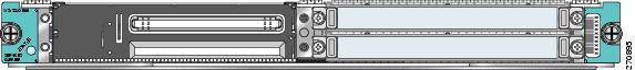
The SSC-600 front panel contains these items:
•![]() One STATUS LED
One STATUS LED
•![]() Two subslots, each capable of holding one VSPA
Two subslots, each capable of holding one VSPA
SSC-600 LED
Table 1-5 describes the operation of the SSC-600 LED.
SSC-600 Physical Specifications
Table 1-6 describes the SSC-600 physical specifications.
VSPA Overview
The following sections describe the VSPA:
VSPA Front Panel
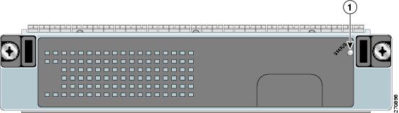
Figure 1-2 shows the VSPA front panel.
Figure 1-2 VSPA Faceplate
|
|
STATUS LED |
||
VSPA LED
Table 1-7 describes the operation of the VSPA LED.
VSPA Physical Specifications
Table 1-8 describes the VSPA physical specifications.
Using the Command-Line Interface
The installation verification procedures described in this document use the Cisco IOS command-line interface (CLI) of the Catalyst 6500 Series switch. To understand the CLI and Cisco IOS command modes, see the Cisco IOS Configuration Fundamentals Command Reference at this URL:
http://www.cisco.com/en/US/docs/ios/fundamentals/command/reference/cf_book.html
For detailed information on configuring the Catalyst 6500 Series switch, see the Catalyst 6500 Release 12.2SXH and Later Software Configuration Guide at this URL:
http://www.cisco.com/en/US/docs/switches/lan/catalyst6500/ios/12.2SX/configuration/guide/book.html
Identifying Slots, Subslots, and Ports
Some CLI commands, such as the show hw-module subslot command, allow you to display information about the VSPA and the SSC-600. These commands require you to specify the physical location of the SSC-600 using the slot variable, or the physical location of the VSPA using the slot/subslot variable.
•![]() slot—Specifies the chassis slot number in the Catalyst 6500 Series switch where the SSC-600 is installed.
slot—Specifies the chassis slot number in the Catalyst 6500 Series switch where the SSC-600 is installed.
•![]() subslot—Specifies the secondary slot of the SSC-600 where the VSPA is installed.
subslot—Specifies the secondary slot of the SSC-600 where the VSPA is installed.
The subslot numbering is indicated by a small numeric label beside the subslot on the faceplate of the SSC-600. In the horizontal card orientation shown in Figure 1-1, the SSC-600 subslot locations are as follows:
•![]() Subslot 0—Left subslot
Subslot 0—Left subslot
•![]() Subslot 1—Right subslot
Subslot 1—Right subslot
For example, to display the operational status of the VSPA installed in the first subslot (subslot 0) of the SSC-600 in chassis slot 3 of a Catalyst 6500 Series switch, enter the following command:
Router# show hw-module subslot 3/0 oir
Module Model Operational Status
------------- -------------------- ------------------------
subslot 3/0 WS-IPSEC-3 ok
Some CLI commands require you to specify the inside and outside ports of the VSPA in the format slot/subslot/port. Although the VSPA ports are not actual Gigabit Ethernet ports, and do not share all properties of external Gigabit Ethernet interfaces, they can be addressed for configuration as Gigabit Ethernet trunk ports, using port numbers as follows:
•![]() Port 1—Inside port, attached to interface VLAN
Port 1—Inside port, attached to interface VLAN
•![]() Port 2—Outside port, attached to port VLAN
Port 2—Outside port, attached to port VLAN
For example, to configure the outside port of a VSPA in the first subslot (subslot 0) of an SSC-600 in slot 6 of a Catalyst 6500 Series switch, enter the following command:
Router(config)# interface GigabitEthernet6/0/2
 Feedback