- Title and Copyright: Multichannel PA-STM-1 Port Adapter Installation and Configuration
- Preface: Multichannel PA-STM-1 Port Adapter
- Overview: Multichannel PA-STM-1 Port Adapter
- Preparing to Install the Multichannel PA-STM-1 Port Adapter
- Removing and Installing the Multichannel PA-STM-1 Port Adapter
- Configuring the Multichannel PA-STM-1 Port Adapter
- Port Adapter Overview
- SDH Overview
- PA-MC-STM-1 Multiplexing Hierarchy
- Features
- PA-MC-STM-1 Optical Fiber Specifications
- LEDs
- Cables, Connectors, and Pinouts
- Management Information Base
- Port Adapter Slot Locations on the Supported Platforms
- Catalyst 6000 Family Switches and Cisco 7600 Series Routers with FlexWAN Module Slot Numbering
- Cisco 7200 VXR Routers Slot Numbering
- Cisco 7200 VXR Routers with the Port Adapter Jacket Card Slot Numbering
- Cisco 7201 Router Slot Numbering
- Cisco 7301 Router Slot Numbering
- Cisco 7304 PCI Port Adapter Carrier Card Slot Numbering
- Cisco 7401ASR Router Slot Numbering
- Cisco 7500 Series Routers VIP Slot Numbering
- Identifying Interface Addresses
- Catalyst 6000 Family Switches and Cisco 7600 Series Routers with FlexWAN Module Interface Addresses
- Cisco 7200 VXR Routers Interface Addresses
- Cisco 7200 VXR Routers with the Port Adapter Jacket Card Interface Addresses
- Cisco 7201 Routers Interface Addresses
- Cisco 7301 Routers Interface Addresses
- Cisco 7304 Routers with Cisco 7304 PCI Port Adapter Carrier Card Interface Addresses
- Cisco 7401ASR Routers Interface Addresses
- Cisco 7500 Series Routers VIP Interface Addresses
Overview
This chapter describes the PA-MC-STM-1 port adapter and contains the following sections:
•![]() PA-MC-STM-1 Multiplexing Hierarchy
PA-MC-STM-1 Multiplexing Hierarchy
•![]() PA-MC-STM-1 Optical Fiber Specifications
PA-MC-STM-1 Optical Fiber Specifications
•![]() LEDs
LEDs
•![]() Cables, Connectors, and Pinouts
Cables, Connectors, and Pinouts
•![]() Port Adapter Slot Locations on the Supported Platforms
Port Adapter Slot Locations on the Supported Platforms
•![]() Identifying Interface Addresses
Identifying Interface Addresses
Port Adapter Overview
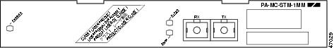
The PA-MC-STM-1, shown in Figure 1-1 and Figure 1-2, is a high-speed, single-port multichannel STM-1 port adapter. You can configure the PA-MC-STM-1 as a multichannel E1 STM-1 port, which can be configured into 63 individual E1 links. Each E1 link can carry a single channel at full or fractional rates, or it can be broken down into multiple DS0 rates.
Two restrictions exist:
•![]() The maximum number of channels is limited to 256 per PA-MC-STM-1.
The maximum number of channels is limited to 256 per PA-MC-STM-1.
•![]() The maximum number of FIFO buffers is 2048. The FIFO buffers are shared among the interfaces; how they are shared is determined by speed. If all the FIFO buffers have been assigned to existing interfaces, a new interface cannot be created, and the "%Insufficient FIFOs to create channel group" error message is seen. FIFO allocation information is provided in Table 1-1, and examples of supported and unsupported configurations are provided in Table 1-2 and Table 1-3.
The maximum number of FIFO buffers is 2048. The FIFO buffers are shared among the interfaces; how they are shared is determined by speed. If all the FIFO buffers have been assigned to existing interfaces, a new interface cannot be created, and the "%Insufficient FIFOs to create channel group" error message is seen. FIFO allocation information is provided in Table 1-1, and examples of supported and unsupported configurations are provided in Table 1-2 and Table 1-3.
Following are three examples of supported and unsupported configurations.
|
|
|
|---|---|
63 E1s -> x 32 FIFOs = |
2016 |
256 DSOs -> 256 x 3 FIFOs = |
768 |
62 E1s + 21 DSOs -> (62 x 32) + (21 x 3) = |
2047 |
|
|
|
|---|---|
258 DS0s -> |
256 interface limit is exceeded |
62 E1s with 31 DSOs -> (62 x 32) + (31 x 3) = |
2077 FIFOs (exceeds 2048 FIFO limit) |
The PA-MC-STM-1 supports up to three TUG-3/AU-3 transport slots numbered 1 to 3. You can configure each TUG-3/AU-3 to carry 21 SDH TU-12s. Each SDH TU-12 is capable of carrying a channelized E1 frame, which can be unchannelized to n 64-Kbps time slots.
Figure 1-1 PA-MC-STM-1SMI—Faceplate View
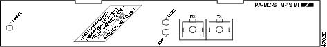
Figure 1-2 PA-MC-STM-1MM—Faceplate View
SDH Overview
Synchronous Digital Hierarchy (SDH) is the international standard for optical digital transmission at hierarchical rates from 155.520 Mbps (STM-1) to 2.5 Gbps (STM-16) and greater.
The International Telecommunications Union Telecommunication Sector (ITU-T) defines a series of SDH transmission rates beginning at 155.520 Mbps as follows:
|
|
|
|---|---|
STM-1 |
155.520 Mbps |
STM-4 |
622.080 Mbps |
STM-16 |
2,488.320 Mbps |
STM-64 |
9,953.280 Mbps |
The PA-MC-STM-1 currently allows transmission over single-mode and multimode optical fiber only. Transmission rates are integral multiples of 51.840 Mbps, which can be used to carry E3 bit-synchronous signals.
The following references discuss concepts and specifications of PPP:
•![]() Simpson, W., Editor, The Point-to-Point Protocol (PPP), RFC 1548, Daydreamer, December 1993.
Simpson, W., Editor, The Point-to-Point Protocol (PPP), RFC 1548, Daydreamer, December 1993.
•![]() Simpson, W., Editor, PPP in HDLC Framing, RFC 1662, Daydreamer, July 1994.
Simpson, W., Editor, PPP in HDLC Framing, RFC 1662, Daydreamer, July 1994.
•![]() Simpson, W., Editor, PPP Over SONET/SDH, RFC 1619, Daydreamer, May 1995.
Simpson, W., Editor, PPP Over SONET/SDH, RFC 1619, Daydreamer, May 1995.
•![]() American National Standard for Telecommunications - Digital Hierarchy - Optical Interface Rates and Formats Specification, ANSI T1.105-1991.
American National Standard for Telecommunications - Digital Hierarchy - Optical Interface Rates and Formats Specification, ANSI T1.105-1991.
•![]() American National Standard for Telecommunications - Synchronous Optical Network (SONET) Payload Mappings, ANSI T1.105.02-1993 draft.
American National Standard for Telecommunications - Synchronous Optical Network (SONET) Payload Mappings, ANSI T1.105.02-1993 draft.
•![]() ITU-T Recommendation G.707, Synchronous Digital Hierarchy Bit Rates, June 1992.
ITU-T Recommendation G.707, Synchronous Digital Hierarchy Bit Rates, June 1992.
PA-MC-STM-1 Multiplexing Hierarchy
Figure 1-3 illustrates the SDH multiplexing structure supported on the PA-MC-STM-1. The PA-MC-STM-1 multiplexing structure is a subset of that defined in ITU-T G.707. At the lowest level, containers (Cs) are input into virtual containers (VCs) with stuffing bits to create a uniform VC payload with a common bit-rate, ready for synchronous multiplexing. Then the VCs are aligned into tributary units (TUs) where pointer processing operations are implemented, allowing the TUs to be multiplexed into TU groups (TUGs). Three TU-12s can be multiplexed into one TUG-2.
Figure 1-3 PA-MC-STM-1 Multiplexing Structure
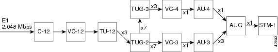
The TUGs are then multiplexed into higher level VCs, which in turn are multiplexed into administration units (AUs). The AUs are then multiplexed into an AU group (AUG) and the final payload from the AUG is then multiplexed into the Synchronous Transport Module (STM).
Features
The PA-MC-STM-1 has the following features:
•![]() One STM-1 port with integrated channel service unit/data service units (CSU/DSUs)
One STM-1 port with integrated channel service unit/data service units (CSU/DSUs)
•![]() 63 E1 ports multiplexed onto a single STM-1 connection
63 E1 ports multiplexed onto a single STM-1 connection
•![]() Channelized E1, fractional E1, and full-rate E1 supported
Channelized E1, fractional E1, and full-rate E1 supported
–![]() Up to 256 usable channels
Up to 256 usable channels
–![]() Internal or network clocking selectable on each E1
Internal or network clocking selectable on each E1
–![]() 64-Kbps DS0 time slots
64-Kbps DS0 time slots
•![]() Network and local loopback capabilities
Network and local loopback capabilities
•![]() Bit error rate testing (BERT) capability on any E1
Bit error rate testing (BERT) capability on any E1
•![]() Alarm detection—alarm indication signal (AIS), Remote Alarm, far-end block error (FEBE), and out of frame (OOF)
Alarm detection—alarm indication signal (AIS), Remote Alarm, far-end block error (FEBE), and out of frame (OOF)
•![]() Support for the following serial encapsulation protocols:
Support for the following serial encapsulation protocols:
–![]() Frame Relay
Frame Relay
–![]() Point-to-Point Protocol (PPP)
Point-to-Point Protocol (PPP)
–![]() High-Level Data Link Control (HDLC)
High-Level Data Link Control (HDLC)
–![]() Switched Multimegabit Data Service (SMDS) Data Exchange Interface (DXI)
Switched Multimegabit Data Service (SMDS) Data Exchange Interface (DXI)
•![]() Support for the following routed protocols:
Support for the following routed protocols:
–![]() Internet Protocol (IP)
Internet Protocol (IP)
–![]() Internetwork Packet Exchange (IPX)
Internetwork Packet Exchange (IPX)
–![]() DECnet
DECnet
•![]() Support for 16-bit or 32-bit cyclic redundancy check (CRC)
Support for 16-bit or 32-bit cyclic redundancy check (CRC)
•![]() Online insertion and removal (OIR) is supported on the Cisco 7200 VXR routers, Cisco 7201 router, Cisco 7301 router, Cisco 7304 router (when installed on the carrier card), Cisco 7401ASR router, and the Cisco 7500 series routers with VIP4-80 or VIP6-80.
Online insertion and removal (OIR) is supported on the Cisco 7200 VXR routers, Cisco 7201 router, Cisco 7301 router, Cisco 7304 router (when installed on the carrier card), Cisco 7401ASR router, and the Cisco 7500 series routers with VIP4-80 or VIP6-80.
•![]() Automatic protection switching (APS)
Automatic protection switching (APS)
PA-MC-STM-1 Optical Fiber Specifications
The PA-MC-STM-1 specification for optical fiber transmission defines two types of fiber: single-mode and multimode. Within the single-mode category, two types of transmission are defined: intermediate reach and long reach. Within the multimode category, only short reach is available. (See Table 1-4 for specifications.)
Modes can be thought of as bundles of light rays entering the fiber at a particular angle. Single-mode fiber allows only one mode of light to propagate through the fiber at one wavelength and polarization, and multimode fiber allows multiple modes of light to propagate through the fiber for each wavelength and polarization.
Multiple modes of light propagating through the fiber travel different distances depending on the entry angles, which causes them to arrive at the destination at different times (a phenomenon called modal dispersion). Model dispersion limits propagation distance in multimode fiber before attenuation does. Therefore, single-mode fiber is capable of higher bandwidth and greater cable run distances than multimode fiber. Table 1-4 lists nominal OC-3 optical parameters for single-mode and multimode optical fiber transmission.

Note ![]() If the distance between two connected stations is greater than the maximum distances listed, significant signal loss can result, making transmission unreliable.
If the distance between two connected stations is greater than the maximum distances listed, significant signal loss can result, making transmission unreliable.
|
Type 1 |
Power |
to Receiver 2 |
|
Budgets |
Between Stations |
|---|---|---|---|---|---|
Single-mode3 intermediate reach |
-15 dBm min. |
-8 dBm |
-28 dBm |
0 to 12 dB |
Up to 9 mi (15 km) |
Multimode4 |
-20 dBm min. |
-8 dBm |
-23 dBm |
0 to 7 dB |
Up to 1.2 mi (2 km) |
1 This table gives nominal OC-3 optical parameters. 2 This value represents the maximum power to which any receiver can be exposed. 3 Complies with ITU-T G.957 standard S.1-1 specification. 4 Complies with Short-Reach OC-3 Specification SR-OC-3. |
To calculate link losses and dispersion losses for your application, refer to the following specifications and documents:
•![]() EIA/TIA-IVa Dispersion Unshifted Single-Mode Fiber
EIA/TIA-IVa Dispersion Unshifted Single-Mode Fiber
•![]() EIA-TIA-IVb Dispersion Shifted Single-Mode Fiber
EIA-TIA-IVb Dispersion Shifted Single-Mode Fiber
•![]() GR-20-CORE Generic Requirements for Optical Fiber and Fiber-Optic Cable
GR-20-CORE Generic Requirements for Optical Fiber and Fiber-Optic Cable
•![]() ITU-T Recommendation G.957 Optical Interfaces for Equipment and Systems Relating to the Synchronous Digital Hierarchy
ITU-T Recommendation G.957 Optical Interfaces for Equipment and Systems Relating to the Synchronous Digital Hierarchy
LEDs
The PA-MC-STM-1 has three LEDs. (See Figure 1-4). The green- or yellow-colored LEDs indicate port adapter status.
Figure 1-4 PA-MC-STM-1 LEDs
After system initialization, the ENABLED LED goes on to indicate that the port adapter has been enabled for operation.
The following conditions must be met before the PA-MC-STM-1 is enabled:
•![]() The PA-MC-STM-1 is correctly connected and is receiving power.
The PA-MC-STM-1 is correctly connected and is receiving power.
•![]() A valid system software image for the port adapter has been downloaded successfully.
A valid system software image for the port adapter has been downloaded successfully.
•![]() The system recognizes the PA-MC-STM-1.
The system recognizes the PA-MC-STM-1.
If any of the above conditions are not met, or if the initialization fails for other reasons, the ENABLED LED does not go on.
Table 1-5 lists LED colors and indications.
1 LOS = loss of signal 2 LOF = loss of frame |
Cables, Connectors, and Pinouts
Use a single-mode or multimode optical fiber interface cable to connect your router or switch to another router or switch. In general, multimode cables are gray or orange, and single-mode cables are yellow.
Note ![]() These cables are not available from Cisco Systems.
These cables are not available from Cisco Systems.
For SDH single-mode and multimode optical fiber connections, use one duplex SC-type connector (see Figure 1-5) or two simplex SC-type connectors (see Figure 1-6).
Figure 1-5 Duplex SC Cable Connector
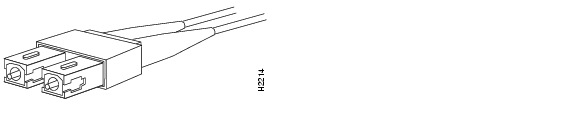
Figure 1-6 Simplex SC Cable Connector
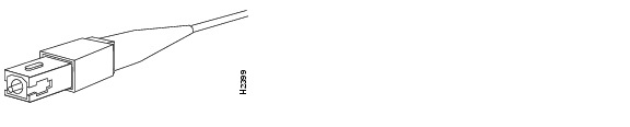
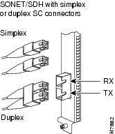
Attach either one duplex optical fiber cable or two simplex optical fiber cables between the port adapter and the device to which the port adapter is connected. Observe the receive (RX) and transmit (TX) cable relationship shown in Figure 1-7.
Figure 1-7 Attaching Simplex or Duplex Optical Fiber Cables
The following warnings apply when you work with optical fiber cable ports.

Warning ![]() Invisible laser radiation may be emitted from the end of the unterminated fiber cable or connector. Do not view directly with optical instruments. Viewing the laser output with certain optical instruments (for example, eye loupes, magnifiers, and microscopes) within a distance of 100 mm may pose an eye hazard. Statement 1056
Invisible laser radiation may be emitted from the end of the unterminated fiber cable or connector. Do not view directly with optical instruments. Viewing the laser output with certain optical instruments (for example, eye loupes, magnifiers, and microscopes) within a distance of 100 mm may pose an eye hazard. Statement 1056
Warning ![]() Class 1 Laser Product. Statement 1008
Class 1 Laser Product. Statement 1008
Warning ![]() Class 1 LED Product. Statement 10 27
Class 1 LED Product. Statement 10 27
Management Information Base
The single-port PA-MC-STM-1 port adapter supports E1 MIB (RFC 1406).
Port Adapter Slot Locations on the Supported Platforms
This section discusses port adapter slot locations on the supported platforms. The illustrations that follow summarize slot location conventions on each platform.
•![]() Catalyst 6000 Family Switches and Cisco 7600 Series Routers with FlexWAN Module Slot Numbering
Catalyst 6000 Family Switches and Cisco 7600 Series Routers with FlexWAN Module Slot Numbering
•![]() Cisco 7200 VXR Routers Slot Numbering
Cisco 7200 VXR Routers Slot Numbering
•![]() Cisco 7200 VXR Routers with the Port Adapter Jacket Card Slot Numbering
Cisco 7200 VXR Routers with the Port Adapter Jacket Card Slot Numbering
•![]() Cisco 7201 Router Slot Numbering
Cisco 7201 Router Slot Numbering
•![]() Cisco 7301 Router Slot Numbering
Cisco 7301 Router Slot Numbering
•![]() Cisco 7304 PCI Port Adapter Carrier Card Slot Numbering
Cisco 7304 PCI Port Adapter Carrier Card Slot Numbering
•![]() Cisco 7401ASR Router Slot Numbering
Cisco 7401ASR Router Slot Numbering
•![]() Cisco 7500 Series Routers VIP Slot Numbering
Cisco 7500 Series Routers VIP Slot Numbering
Catalyst 6000 Family Switches and Cisco 7600 Series Routers with FlexWAN Module Slot Numbering
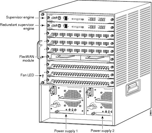
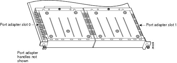
The FlexWAN module can be installed in any slot of a Catalyst 6000 family switch or a Cisco 7600 series router except slot 1, which is reserved for the supervisor engine. Port adapters can be installed into either module bay 0 or module bay 1 on the FlexWAN module. The bays are numbered from left to right on the FlexWAN module. Figure 1-8 shows a FlexWAN module with two blank port adapters installed. The slot numbering is the same for Catalyst 6000 family switches and Cisco 7600 series routers.
Note ![]() Slot 1 is reserved for the supervisor engine. If a redundant supervisor engine is used, it would go in slot 2; otherwise, slot 2 can be used for other modules.
Slot 1 is reserved for the supervisor engine. If a redundant supervisor engine is used, it would go in slot 2; otherwise, slot 2 can be used for other modules.
Figure 1-8 Catalyst 6000 Family Switch with Port Adapters Installed on FlexWAN Module
Cisco 7603 routers have two slots for port adapters. You can place the port adapters in either of the FlexWAN module slots (slot 2 or 3). Slots 1 is always reserved for the supervisor engine.
Cisco 7606 routers have five slots for port adapters. You can place the port adapters in any of the FlexWAN module slots (slots 2 through 6). Slot 1 is always reserved for the supervisor engine.
Cisco 7609 routers have eight slots for port adapters. You can place the port adapters in any of the FlexWAN module slots (slots 2 through 9). Slots 1 is always reserved for the supervisor engine.
Cisco 7200 VXR Routers Slot Numbering
Cisco 7204VXR routers have four slots for port adapters, and one slot for an input/output (I/O) controller. The slots are numbered from the lower left to the upper right, beginning with slot 1 and continuing through slot 4. You can place a port adapter in any of the slots (slot 1 through slot 4). Slot 0 is always reserved for the I/O controller. The Cisco 7204VXR router is not shown.
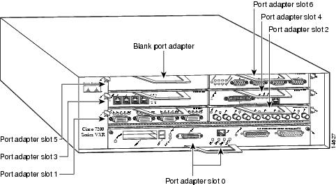
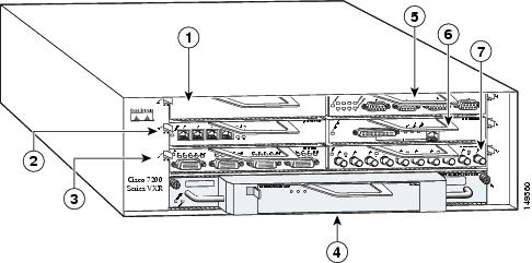
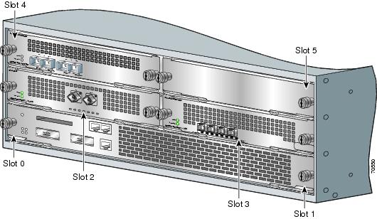
Cisco 7206VXR routers have six slots for port adapters, and one slot for an input/output (I/O) controller. The slots are numbered from the lower left to the upper right, beginning with slot 1 and continuing through slot 6. You can place a port adapter in any of the six slots (slot 1 through slot 6). Slot 0 is always reserved for the I/O controller. Figure 1-9 shows the slot numbering on a Cisco 7206VXR router.
Figure 1-9 Port Adapter Slots in the Cisco 7206VXR Router
Cisco 7200 VXR Routers with the Port Adapter Jacket Card Slot Numbering
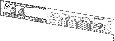
With an NPE-G1 or NPE-G2 installed, port adapter slot 0 of the Cisco 7204VXR router or the Cisco 7206VXR router can accept the Port Adapter Jacket Card. When the Port Adapter Jacket Card resides in port adapter slot 0, the port adapter in the Port Adapter Jacket Card is in port adapter slot 5 on the Cisco 7204 VXR router, or port adapter slot 7 on the Cisco 7206 VXR router. Figure 1-10 shows the slot numbering of port adapters on a Cisco 7206 VXR router when a Port Adapter Jacket Card is installed.
Figure 1-10 Port Adapter Slots in the Cisco 7206 VXR Router with the Port Adapter Jacket Card
|
|
Slot 5 |
|
Slot 6 |
|
|
Slot 3 |
|
Slot 4 |
|
|
Slot 1 |
|
Slot 2 |
|
|
Slot 7-port adapter (slot 0-Jacket Card) |
Cisco 7201 Router Slot Numbering
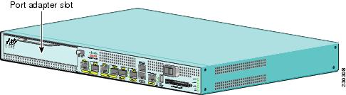
Figure 1-11 shows the front view of a Cisco 7201 router with a port adapter installed. There is only one port adapter slot (slot 1) in a Cisco 7201 router.
Figure 1-11 Port Adapter Slot in the Cisco 7201 Router
Cisco 7301 Router Slot Numbering
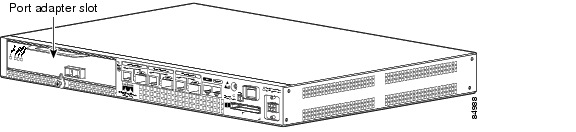
Figure 1-12 shows the front view of a Cisco 7301 router with a port adapter installed. There is only one port adapter slot (slot 1) in a Cisco 7301 router.
Figure 1-12 Port Adapter Slot in the Cisco 7301 Router
Cisco 7304 PCI Port Adapter Carrier Card Slot Numbering
The Cisco 7304 PCI Port Adapter Carrier Card installs in Cisco 7304 router module slots 2 through 5. Figure 1-13 shows a Cisco 7304 PCI Port Adapter Carrier Card with a port adapter installed. The Cisco 7304 PCI Port Adapter Carrier Card accepts one single-width port adapter.
Figure 1-14 shows the module slot numbering on a Cisco 7304 router. The port adapter slot number is the same as the module slot number. Slot 0 and slot 1 are reserved for the NPE module or NSE module.
Figure 1-13 Cisco 7304 PCI Port Adapter Carrier Card—Port Adapter Installed
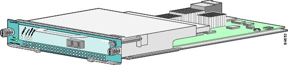
Figure 1-14 Module Slots on the Cisco 7304 Router
Cisco 7401ASR Router Slot Numbering
Figure 1-15 shows the front view of the Cisco 7401ASR router with a port adapter installed. There is only one port adapter slot (slot 1) in a Cisco 7401ASR router.
Figure 1-15 Port Adapter Slot in the Cisco 7401ASR Router
Cisco 7500 Series Routers VIP Slot Numbering
Port adapters are supported on the VIPs (versatile interface processors) used in Cisco 7500 series routers. In the Cisco 7505 router, the VIP motherboard is installed horizontally in the VIP slot. In the Cisco 7507 router and Cisco 7513 router, the VIP motherboard is installed vertically in the VIP slot. A port adapter can be installed in either bay (port adapter slot 0 or 1) on the VIP. The bays are numbered from left to right on the VIP. Figure 1-16 shows the slot numbering on a VIP.
Figure 1-16 VIP Slot Locations
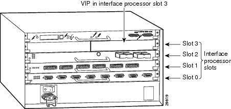
Cisco 7505 routers have four slots for port adapters, and one slot for an RSP. The slots are numbered from bottom to top. You can place a port adapter in any of the VIP interface slots (slot 0 through 3). One slot is always reserved for the RSP. Figure 1-17 shows the slot numbering on a Cisco 7505 router.
Figure 1-17 VIP Slots in the Cisco 7505 Router
Cisco 7507 routers have five slots for port adapters, and two slots for RSPs. The slots are numbered from left to right. You can place a port adapter in any of the VIP interface slots (slot 0, 1, 4, 5, or 6). Slots 2 and 3 are always reserved for RSPs. The Cisco 7507 router is not shown.
Cisco 7513 routers have eleven slots for port adapters, and two slots for RSPs. The slots are numbered from left to right. You can place a port adapter in any of the VIP interface slots (slots 0 through 5, or slots 9 through 12). Slots 6 and 7 are always reserved for RSPs. The Cisco 7513 router is not shown.
Identifying Interface Addresses
This section describes how to identify interface addresses for the PA-MC-STM-1 in supported platforms. Interface addresses specify the actual physical location of each interface on a router or switch.
Interfaces on a PA-MC-STM-1 installed in a router maintain the same address regardless of whether other port adapters are installed or removed. However, when you move a port adapter to a different slot, the first number in the interface address changes to reflect the new port adapter slot number.
Interfaces on a PA-MC-STM-1 installed in a FlexWAN module or VIP maintain the same address regardless of whether other modules or interface processors are installed or removed. However, when you move a FlexWAN module or VIP to a different slot, the module or interface processor slot number changes to reflect the new module or interface processor slot.
Note ![]() Interface ports are numbered from left to right starting with 0.
Interface ports are numbered from left to right starting with 0.
The following subsections describe the interface address formats for the supported platforms:
•![]() Catalyst 6000 Family Switches and Cisco 7600 Series Routers with FlexWAN Module Interface Addresses
Catalyst 6000 Family Switches and Cisco 7600 Series Routers with FlexWAN Module Interface Addresses
•![]() Cisco 7200 VXR Routers Interface Addresses
Cisco 7200 VXR Routers Interface Addresses
•![]() Cisco 7200 VXR Routers with the Port Adapter Jacket Card Interface Addresses
Cisco 7200 VXR Routers with the Port Adapter Jacket Card Interface Addresses
•![]() Cisco 7201 Routers Interface Addresses
Cisco 7201 Routers Interface Addresses
•![]() Cisco 7301 Routers Interface Addresses
Cisco 7301 Routers Interface Addresses
•![]() Cisco 7304 Routers with Cisco 7304 PCI Port Adapter Carrier Card Interface Addresses
Cisco 7304 Routers with Cisco 7304 PCI Port Adapter Carrier Card Interface Addresses
•![]() Cisco 7401ASR Routers Interface Addresses
Cisco 7401ASR Routers Interface Addresses
•![]() Cisco 7500 Series Routers VIP Interface Addresses
Cisco 7500 Series Routers VIP Interface Addresses
Table 1-6 summarizes the interface address formats for the supported platforms.
|
|
|
|
|
|---|---|---|---|
Catalyst 6000 family switches and Cisco 7600 series routers (7603, 7606, 7609) with FlexWAN |
Module-slot-number/port-adapter-bay-number/ |
Module slot —21 through 9 (depends on the number of slots in the switch/router) Port adapter bay—0 or 1 Interface port—0 |
3/0/0 |
Cisco 7200 VXR series routers (7204VXR, 7206VXR) |
Port-adapter-slot-number/interface-port-number |
Port adapter slot—12 through 6 (depends on the number of slots in the router) Interface port—0 |
1/0 |
Port Adapter Jacket Card with the Cisco 7200 VXR router3 |
Port-adapter-slot-number/interface-port-number |
Port adapter slot—1 through 7 (depends on the number of slots in the router)4 Interface port—0 |
1/0 |
Cisco 7201 router |
Port-adapter-slot-number/interface-port number |
Port adapter slot—always 1 Interface port—0 |
1/0 |
Cisco 7301 router |
Port-adapter-slot-number/interface-port number |
Port adapter slot—always 1 Interface port—0 |
1/0 |
Cisco 7304 PCI port adapter carrier card in Cisco 7304 router |
Module-slot-number/interface-port-number |
Module slot—2 through 5 Interface port—0 |
3/0 |
Cisco 7401ASR router |
Port-adapter-slot-number/interface-port number |
Port adapter slot—always 1 Interface port—0 |
1/0 |
Cisco 7500 series routers with VIP4-80, VIP6-80 |
Interface-processor-slot-number/port-adapter |
Interface processor slot—0 through 12 (depends on the number of slots in the router) Port adapter slot— 0 or 1 Interface port—0 |
3/1/0 |
1 Slot 1 is reserved for the supervisor engine. If a redundant supervisor engine is used, it must go in slot 2; otherwise, slot 2 can be used for other modules. 2 Port adapter slot 0 is reserved for the Fast Ethernet port on the I/O controller (if present). 3 Port adapter slot 0 can accept the Port Adapter Jacket Card if an NPE-G1 or NPE-G2 are installed, but becomes slot 5 on a Cisco 7204VXR router when a port adapter is installed or slot 7 on a Cisco 7206VXR router when a port adapter is installed. 4 Port adapter slot 0 is reserved for the Fast Ethernet port on the I/O controller (if present). |
Catalyst 6000 Family Switches and Cisco 7600 Series Routers with FlexWAN Module Interface Addresses
In Catalyst 6000 family switches and Cisco 7600 series routers, port adapters are installed in a FlexWAN module, which installs in module slots 2 through 9 (depending on the number of slots in the router). The port adapter can be installed in either bay (port adapter bay 0 or 1) on the FlexWAN module. See Figure 1-8.
The interface address is composed of a three-part number in the format module-slot-number/port-adapter-bay-number/interface-port-number. See Table 1-6.
The first number identifies the module slot of the chassis in which the FlexWAN module is installed (slot 2 through slot 3, 6,or 9 depending on the number of slots in the chassis). These module slots are generally numbered from top to bottom, starting with 1. The Cisco 7609 is the exception with slots numbered right to left, starting with 1.
The second number identifies the bay of the FlexWAN module in which the port adapter is installed (0 or 1). The bays are numbered from left to right on the FlexWAN module.
The third number identifies the physical port number on the port adapter. The PA-MC-STM is a single-port port adapter, therefore the port is always 0.
For example, if a single-port port adapter is installed in the FlexWAN module, which is inserted in module slot 3, port adapter bay 0, then the interface address of the port adapter would be 3/0/0 (module slot 3, port adapter bay 0, and port 0). If the same port adapter is in port adapter bay 1 on the FlexWAN module, the interface addresses would be numbered 3/1/0.
Note ![]() The FlexWAN module physical port address begins with slot 0, which differs from the conventional Catalyst 6000 family port address, which begins with slot 1.
The FlexWAN module physical port address begins with slot 0, which differs from the conventional Catalyst 6000 family port address, which begins with slot 1.
Cisco 7200 VXR Routers Interface Addresses
In Cisco 7200 VXR routers, port adapter slots are numbered from the lower left to the upper right, beginning with slot 1 and continuing through slot 4 for the Cisco 7204VXR router, and slot 6 for the Cisco 7206VXR router. Port adapters can be installed in any available port adapter slot from 1 through 6 (depending on the number of slots in the router). Slot 0 is reserved for the I/O controller. See Figure 1-9.
The interface address is composed of a two-part number in the format port-adapter-slot-number/interface-port-number. See Table 1-6. For example, if a single-port PA-MC-STM-1 is installed in slot 1of a Cisco 7200 VXR router, the interface address would be 1/0. If a single-port PA-MC-STM-1 is installed in slot 4, the interface address would be 4/0.
Cisco 7200 VXR Routers with the Port Adapter Jacket Card Interface Addresses
With an NPE-G1 or NPE-G2 installed, port adapter slot 0 of Cisco 7204VXR router or Cisco 7206VXR router can accept the Port Adapter Jacket Card. When the Port Adapter Jacket Card resides in port adapter slot 0, the port adapter in the Port Adapter Jacket Card is in port adapter slot 5 on the Cisco 7204 VXR router, or port adapter slot 7 on the Cisco 7206 VXR router. See Figure 1-10
The interface address is composed of a two-part number in the format port-adapter-slot-number/interface-port-number. See Table 1-6. For example, if a single-port PA-MC-STM-1 is installed in a Port Adapter Jacket Card in the slot formerly known as slot 0 on a Cisco 7204VXR router, but now known as slot 5, the interface address would be 5/0 (slot 5 and interface port 0). If a single-port PA-MC-STM-1 is installed in a Port Adapter Jacket Card in the slot formerly known as slot 0 on a Cisco 7206VXR router, but now known as slot 7, the interface address would be 7/0 (slot 7 and interface port 0).
Cisco 7201 Routers Interface Addresses
In the Cisco 7201 router, only one slot accepts port adapters and it is numbered as slot 1. See Figure 1-11.
The interface address is composed of a two-part number in the format port-adapter-slot-number/interface-port-number. See Table 1-6. For example, if a single-port PA-MC-STM-1 is installed in a Cisco 7201 router, the interface address would be 1/0.
Cisco 7301 Routers Interface Addresses
In the Cisco 7201 router, only one slot accepts port adapters and it is numbered as slot 1. See Figure 1-12.
The interface address is composed of a two-part number in the format port-adapter-slot-number/interface-port-number. See Table 1-6. For example, if a single-port PA-MC-STM-1 is installed in a Cisco 7201 router, the interface address would be 1/0.
Cisco 7304 Routers with Cisco 7304 PCI Port Adapter Carrier Card Interface Addresses
In the Cisco 7304 router, port adapters are installed in a Cisco 7304 PCI port adapter carrier card, which installs in Cisco 7304 router module slots 2 through 5. The port adapter slot number is the same as the module slot number. See Figure 1-13 and Figure 1-14.
The interface address is composed of a two-part number in the format module-slot-number/interface-port-number. See Table 1-6. For example, if a single-port PA-MC-STM-1 is installed in the Cisco 7304 PCI port adapter carrier card in Cisco 7304 router module slot 3, the interface address would be 3/0.
Cisco 7401ASR Routers Interface Addresses
In the Cisco 7401ASR router, only one slot accepts port adapters and it is numbered as slot 1. See Figure 1-15
The interface address is composed of a two-part number in the format port-adapter-slot-number/interface-port-number. See Table 1-6. For example, if a single-port PA-MC-STM-1 is installed on a Cisco 7401ASR router, the interface address would be 1/0.
Cisco 7500 Series Routers VIP Interface Addresses
In Cisco 7500 series routers, port adapters are installed on a versatile interface processor (VIP), which installs in interface processor slots 0 through 12 (depending on the number of slots in the router). The port adapter can be installed in either bay (port adapter slot 0 or 1) on the VIP. See Figure 1-16, and Figure 1-17.
The interface address for the VIP is composed of a three-part number in the format interface-processor-slot-number/port-adapter-slot-number/interface-port-number. See Table 1-6.
The first number identifies the slot in which the VIP is installed (slot 0 through 12, depending on the number of slots in the router). These processor slots are numbered from bottom to top starting with 0.
The second number identifies the bay (port adapter slot) on the VIP in which the port adapter is installed (0 or 1). The bays are numbered from left to right on the VIP.
The third number identifies the physical port number (interface port number) on the port adapter. The port numbers always begin at 0 and are numbered from left to right. The number of additional ports depends on the number of ports on the port adapter. The PA-MC-STM-1 is a single-port port adapter, therefore the port is always 0.
For example, if a single-port PA-MC-STM-1 is installed in a VIP in interface processor slot 3, port adapter slot 1, the interface addresses would be 3/1/0. If the PA-MC-STM-1 is in port adapter slot 0 on the VIP, the same interface address would be 3/0/0.
Note ![]() Although the processor slots in the seven-slot Cisco 7507 and the thirteen-slot Cisco 7513 chassis are vertically oriented and those in the five-slot Cisco 7505 chassis are horizontally oriented, all Cisco 7500 series routers use the same method for slot and port numbering.
Although the processor slots in the seven-slot Cisco 7507 and the thirteen-slot Cisco 7513 chassis are vertically oriented and those in the five-slot Cisco 7505 chassis are horizontally oriented, all Cisco 7500 series routers use the same method for slot and port numbering.
 Feedback