- Title and copyright: PA-F/FD-SM and PA-F/FD-MM Full-Duplex FDDI Port Adapter Installation and Configuration
- Preface: PA-F/FD-SM and PA-F/FD-MM Full-Duplex FDDI Port Adapter Installation and Configuration
- Overview: PA-F/FD-SM and PA-F/FD-MM Full-Duplex FDDI Port Adapter Installation and Configuration
- Preparing to Install the PA-F/FD Port Adapter
- Attaching the PA-F/FD Port Adapter Cables
- Configuring the PA-F/FD Port Adapter
Overview
This chapter describes the PA-F/FD-SM and PA-F/FD-MM full-duplex FDDI port adapters and contains the following sections:
•![]() LEDs
LEDs
•![]() Port Adapter Locations on the Supported Platforms
Port Adapter Locations on the Supported Platforms
Port Adapter Overview
The PA-F/FD port adapters provide a full-duplex FDDI interface for both single-mode and multimode fiber-optic cable. The two physical ports (PHY A and PHY B) are available with either single-mode (SC) or multimode media interface connector (MIC) receptacles. Each FDDI connection allows a maximum bandwidth of 100 Mbps, per the FDDI standard for half-duplex operation, and 200-Mbps aggregate bandwidth with full-duplex operation enabled.
The following FDDI port adapter combinations are available:
•![]() PA-F/FD-MM—FDDI PHY-A multimode, PHY-B multimode port adapter with optical bypass switch capability and full-duplex capability (see )
PA-F/FD-MM—FDDI PHY-A multimode, PHY-B multimode port adapter with optical bypass switch capability and full-duplex capability (see )
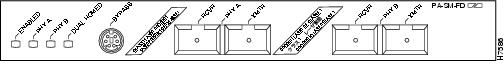
•![]() PA-F/FD-SM—FDDI PHY-A single-mode, PHY-B single-mode port adapter with optical bypass switch capability and full-duplex capability (see )
PA-F/FD-SM—FDDI PHY-A single-mode, PHY-B single-mode port adapter with optical bypass switch capability and full-duplex capability (see )
Figure 1-1 PA-F/FD-MM Faceplate
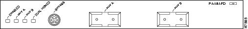
Figure 1-2 PA-F/FD-SM Faceplate

Warning ![]() Invisible laser radiation may be emitted from the aperture ports of the single-mode FDDI products when no fiber cable is connected. Avoid exposure and do not stare into open apertures.
Invisible laser radiation may be emitted from the aperture ports of the single-mode FDDI products when no fiber cable is connected. Avoid exposure and do not stare into open apertures.
FDDI Overview
FDDI, which specifies a 100-Mbps, wire-speed, token-passing dual-ring network using fiber-optic transmission media, is defined by the ANSI X3.1 standard and by ISO 9314, the international version of the ANSI standard. A FDDI network comprises two token-passing fiber-optic rings: a primary ring and a secondary ring.
A ring consists of two or more point-to-point connections between adjacent stations. On most networks, the primary ring is used for data communication, and the secondary ring is used as a backup. Single attachment stations (SASs) attach to one ring and are typically attached through a concentrator; Class A, or dual attachment stations (DASs), attach to both rings.
shows a typical FDDI configuration with both dual-attached and single-attached connections. SASs typically attach to the primary ring through a concentrator, which provides connections for multiple single-attached devices. The concentrator ensures that a failure or power down of any SAS does not interrupt the ring. SAS use one transmit port and one receive port to attach to the single ring. DASs (Class A) have two physical ports, designated PHY A and PHY B, each of which connects the station to both the primary and the secondary rings. Each port is a receiver for one ring and a transmitter for the other. For example, PHY A receives traffic from the primary ring, and PHY B transmits to it.
Figure 1-3 Typical Configuration with DAS, Concentrator, and SASs

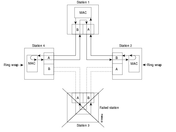
The dual rings in a FDDI network provide fault tolerance. If a station on a dual ring shuts down or fails, such as Station 3 in , the ring automatically wraps (doubles back on itself) to form a single contiguous ring. This removes the failed station from the ring, but allows the other stations to continue operation. In , the ring wraps to eliminate Station 3 and forms a smaller ring that includes only Stations 1, 2, and 4. A second failure could cause the ring to wrap in both directions from the point of failure, which would segment the ring into two separate rings that could not communicate with each other.
For example, if Station 1 in fails after Station 3 fails, Stations 2 and 4 will each be isolated because no path for communication exists between them. Subsequent failures cause additional segmentation.
Figure 1-4 DAS Station Failure and Ring Recovery Example
Optical Bypass Switch Overview
Optical bypass switching avoids segmentation by eliminating failed stations from a ring. An optical bypass switch allows the light signal to pass directly through it, completely bypassing the failed or shutdown station.

Note ![]() For example, if an optical bypass switch had been installed at Station 3 in the sample ring in , it would have allowed the light signal to pass through the switch and maintain its existing path and direction without wrapping back on itself.
For example, if an optical bypass switch had been installed at Station 3 in the sample ring in , it would have allowed the light signal to pass through the switch and maintain its existing path and direction without wrapping back on itself.
The FDDI port adapters have an optical bypass switch feature by way of a DIN connection. During normal operation, an optical bypass switch allows the light signal to pass uninterrupted directly through itself. When a station with a bypass switch fails, the bypass switch reroutes the signal back onto the ring before it reaches the failed station, so the ring does not have to wrap back on itself.
shows an optical bypass switch installed at Station 1. In the normal configuration shown, Station 1 is functioning normally, so the optical bypass switch appears transparent. The switch essentially allows the signals to pass through it without interruption. However, if Station 1 fails, the optical bypass switch enables the bypassed configuration shown on the right in .
Figure 1-5 Optical Bypass Operation on a DAS
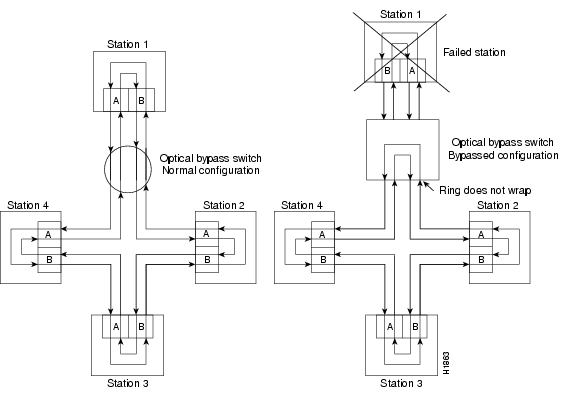
The optical bypass switch reroutes the light signal by intercepting it before it reaches the failed Station 1 and sends it back out to the ring. This rerouting allows the signal to maintain its existing path and direction without wrapping back on itself. However, stations that are operating normally repeat the signal when sending it back out to the ring. Optical bypass switches do not repeat or drive the signal (they just allow the signal to pass through them), so significant signal loss can occur when the downstream neighbor (the next station on the ring) is far away.
Another technique for fault tolerance is dual homing, where critical devices are attached to two concentrators. Only the designated primary concentrator is active unless it (or its link) fails. If the primary does fail, the backup (passive) concentrator is automatically activated and sustains the ring.
FDDI Full-Duplex Overview
FDDI full-duplex allows a FDDI ring with exactly two stations to transform the ring into a full-duplex, point-to-point topology. In order to operate in full-duplex mode, there must be only two stations on the ring, the two stations must be capable of operating in full-duplex mode, and both stations must complete a full-duplex autoconfiguration protocol. There is no FDDI token in full-duplex mode.
Full-duplex autoconfiguration protocol allows a station to dynamically and automatically operate in either half-duplex (or ring) or full-duplex mode, and ensures that the stations fall back to ring mode when a configuration change occurs, such as a third station joining the ring.
After booting up, the stations begin operation in ring mode. While the station performs the full-duplex autoconfiguration protocol, the station continues to provide data-link services to its users. Under normal conditions, the transition between half-duplex mode and full-duplex mode is transparent to the data-link users. The data-link services provided by full-duplex mode are functionally the same as the services provided by half-duplex mode.
FDDI Specifications
Typically, FDDI uses two types of fiber-optic cable:
•![]() Single-mode (also called monomode) optical fiber with SC-type, duplex and simplex connectors
Single-mode (also called monomode) optical fiber with SC-type, duplex and simplex connectors
•![]() Multimode optical fiber with media interface connectors (MICs)
Multimode optical fiber with media interface connectors (MICs)
Mode refers to the angle at which light rays (signals) are reflected and propagated through the optical fiber core, which acts as a waveguide for the light signals. Multimode fiber has a relatively thick core (62.5/125-micron) that reflects light rays at many angles. Single-mode fiber has a narrow core (8.7 to 10/125-micron) that allows the light to enter only at a single angle.
Although multimode fiber allows more light signals to enter at a greater variety of angles (modes), the different angles create multiple propagation paths that cause the signals to spread out in time and limit the rate at which data can be accurately received. This distortion does not occur on the single path of the single-mode signal; therefore, single-mode fiber is capable of higher bandwidth and greater cable run distances than multimode fiber. In addition, multimode transmitters usually use LEDs as a light source, and single-mode transmitters use a laser diode, which is capable of sustaining faster data rates. Both transmitter types use a photodiode detector at the receiver to translate the light signal into electrical signals.
The FDDI standard sets total fiber lengths of 1.2 miles (2 kilometers) for multimode fiber and 9.3 miles (15 kilometers) for single-mode fiber. (The maximum circumference of the FDDI network is only half the specified distance because of signal wrapping or loopback that occurs during fault correction.) The FDDI standard allows a maximum of 500 stations with a maximum distance between active stations of 1.2 miles (2 kilometers).
Table 1-1 lists the signal descriptions for the mini-DIN optical bypass switch available on the FDDI port adapters. The mini-DIN-to-DIN adapter cable (Product Number CAB-FMDD=) allows connection to an optical bypass switch with a DIN connector (which is larger than the mini-DIN connector on the FDDI port adapters).
Note ![]() Up to 160 milliamperes (mA) of current can be supplied to the optical bypass switch.
Up to 160 milliamperes (mA) of current can be supplied to the optical bypass switch.
The FDDI port adapter implementation complies with Version 6.1 of the X3T9.5 FDDI specification, offering a Class A dual attachment interface that supports the fault-recovery methods of DAS. The FDDI port adapter supports dual homing and optical bypass and complies with ANSI X3.1 and ISO 9314 FDDI standards.
Maximum Transmission Distances for FDDI Connections
The maximum transmission distances for single-mode and multimode FDDI stations are shown in Table 1-2. If the distance between two connected stations is greater than the maximum distance shown, significant signal loss can result.
Table 1-2 FDDI Maximum Transmission Distances
|
|
|
|---|---|
Single-mode |
Up to 9.3 miles (up to 15 km) |
Multimode |
Up to 1.2 miles (up to 2 km) |
FDDI Port Adapter Optical Power Parameters
The multimode and single-mode optical-fiber connections conform to the following optical power parameters:
•![]() Output power: -19 to -14 dBm
Output power: -19 to -14 dBm
•![]() Input power: -31 to -14 dBm
Input power: -31 to -14 dBm
•![]() Input sensitivity: -31 dBm @ 2.5x10-10 bit error rate @ 125 Mbps
Input sensitivity: -31 dBm @ 2.5x10-10 bit error rate @ 125 Mbps
LEDs
The PA-F/FD contains the enabled LED, which is standard on all port adapters, and status LEDs for each port. After system initialization, the enabled LED goes on to indicate that the port adapter has been enabled for operation. (The LEDs are shown in .) The LEDs on both the PA-F/FD-SM and the PA-F/FD-MM are identical to the LEDs shown in and are described in Table 1-3.
Figure 1-6 LEDs on the PA-F/FD—Partial Faceplate
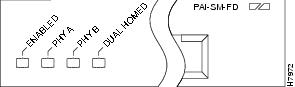
The following conditions must be met before the enabled LED goes on:
•![]() The port adapter is correctly connected and receiving power.
The port adapter is correctly connected and receiving power.
•![]() The FDDI-equipped card or chassis contains a valid microcode version that has been downloaded successfully.
The FDDI-equipped card or chassis contains a valid microcode version that has been downloaded successfully.
•![]() The bus recognizes the FDDI-equipped card or chassis.
The bus recognizes the FDDI-equipped card or chassis.
If any of these conditions is not met, or if the initialization fails for other reasons, the enabled LED does not go on.
Table 1-3
PA-F/FD LEDs
The LED states are described in Table 1-4.
Table 1-4
PA-F/FD LED States
Cables and Connectors
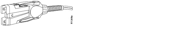
The interface receptacles on the PA-F/FD are MICs for multimode and SC-type connectors for simplex and duplex single-mode applications. The multimode receptacle is a FDDI-standard physical sublayer (PHY) connector that encodes and decodes the data into a format acceptable for fiber transmission. The multimode receptacle accepts standard 62.5/125-micron multimode fiber-optic cable using the MIC and, with proper cable terminators, can accept 50/125-micron fiber-optic cable. Fiber-optic cables are commercially available; they are not available from Cisco Systems. Multimode operation uses the integrated MIC shown in Figure 1-7 at both the port adapter end and the network end.
Figure 1-7 Multimode FDDI Network Interface MIC
For FDDI single-mode connections, use one duplex SC-type connector (see Figure 1-8) or two single SC-type connectors at both the port adapter end and the network end (see Figure 1-9). Single-mode optical fiber cable has a narrow core (8.7 to 10/125-micron), which allows the light to enter only at a single angle.
Figure 1-8 Duplex SC-type Connector

Figure 1-9 Simplex SC-type Connector

Warning ![]() Invisible laser radiation may be emitted from the aperture ports of the single-mode FDDI products when no fiber cable is connected. Avoid exposure and do not stare into open apertures.
Invisible laser radiation may be emitted from the aperture ports of the single-mode FDDI products when no fiber cable is connected. Avoid exposure and do not stare into open apertures.
Port Adapter Locations on the Supported Platforms
This section provides information about where you can install the PA-F/FD on the VIP, the Catalyst RSM/VIP2, and in the Cisco 7200 series routers (including a Cisco 7206 as a router shelf in a Cisco AS5800 Universal Access Server).
The PA-F/FD can be installed on the VIP or Catalyst RSM/VIP2 in port adapter slot 0 or port adapter slot 1 or in the Cisco 7200 series routers in any of the chassis port adapter slots. Port adapters have a handle attached, but this handle is occasionally not shown in this publication to allow a full view of detail on the port adapter's faceplate.
Note ![]() Interface ports are numbered from left to right starting with 0.
Interface ports are numbered from left to right starting with 0.
Note ![]() The PA-F/FD-SM and PA-F/FD-MM are not supported on Cisco 7200 VXR routers.
The PA-F/FD-SM and PA-F/FD-MM are not supported on Cisco 7200 VXR routers.
Figure 1-10 shows a VIP with installed port adapters. With the VIP oriented as shown, the left port adapter is in port adapter slot 0, and the right port adapter is in port adapter slot 1.
Figure 1-10 VIP Motherboard with Two Port Adapters Installed—Horizontal Orientation
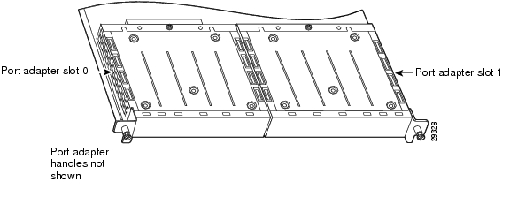
Note ![]() In the Cisco 7000, Cisco 7507, and Cisco 7513 chassis, the VIP is installed vertically. In the Cisco 7010 and Cisco 7505 chassis the VIP is installed horizontally.
In the Cisco 7000, Cisco 7507, and Cisco 7513 chassis, the VIP is installed vertically. In the Cisco 7010 and Cisco 7505 chassis the VIP is installed horizontally.
Note ![]() Refer to Chapter 4 for illustrations of the PA-F/FD port adapters installed on a Catalyst RSM/VIP2-40.
Refer to Chapter 4 for illustrations of the PA-F/FD port adapters installed on a Catalyst RSM/VIP2-40.
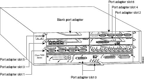
Figure 1-11 shows a Cisco 7206 with port adapters installed. In the Cisco 7206, port adapter slot 1 is in the lower left position, and port adapter slot 6 is in the upper right position.
Figure 1-11 Port Adapters in the Cisco 7206
 Feedback