Attaching the PA-GE Cables
To continue your PA-GE port adapter installation, you must attach the cables to the Gigabit Interface Converter (GBIC) on your port adapter.
Your PA-GE shipped with a GBIC installed, depending on the PA-GE model you ordered (1000BASE-SX, 1000BASE-LX, 1000BASE-LH, or 1000BASE-ZX).
This chapter contains the following sections:
•![]() Connecting Cables to the PA-GE
Connecting Cables to the PA-GE
•![]() Replacing a GBIC in the PA-GE
Replacing a GBIC in the PA-GE

Note ![]() If your PA-GE arrived without the GBIC installed and you need to install it now, or you need to change your GBIC for another reason, use the procedures in the "Replacing a GBIC in the PA-GE" section.
If your PA-GE arrived without the GBIC installed and you need to install it now, or you need to change your GBIC for another reason, use the procedures in the "Replacing a GBIC in the PA-GE" section.
If your GBIC is installed, use the procedures in the "Connecting Cables to the PA-GE" section that follows.
Connecting Cables to the PA-GE
The two cabling options for the PA-GE are discussed in the following sections:
•![]() Attaching Multimode and Single-Mode Optical Fiber Cables to a GBIC
Attaching Multimode and Single-Mode Optical Fiber Cables to a GBIC
Use this cabling option for the following connections:
–![]() PA-GE with a GBIC-SX
PA-GE with a GBIC-SX
–![]() PA-GE with a GBIC-LX or a GBIC-LH, when you expect transmission distances to be less than 984.25 feet (300 meters) over 50/125-micron or 62.5/125-micron multimode fiber
PA-GE with a GBIC-LX or a GBIC-LH, when you expect transmission distances to be less than 984.25 feet (300 meters) over 50/125-micron or 62.5/125-micron multimode fiber
–![]() PA-GE with a GBIC-ZX
PA-GE with a GBIC-ZX
(For specific information about multimode and single-mode optical fiber cables, refer to Table 1-5 and the "Optical Fiber Cables" section on page 1-9.)
•![]() Attaching a Mode Conditioning Patch Cord to a GBIC-LX or GBIC-LH
Attaching a Mode Conditioning Patch Cord to a GBIC-LX or GBIC-LH
Use this cabling option for a PA-GE with a GBIC-LX or a GBIC-LH when you expect transmission distances to be greater than 984.25 feet (300 meters) over 50/125-micron or 62.5/125-micron multimode fiber. (For specific information about the mode conditioning patch cord, see the "Mode Conditioning Patch Cord with a Multimode GBIC-LX and GBIC-LH" section on page 1-10.)

Attaching Multimode and Single-Mode Optical Fiber Cables to a GBIC
This section provides the cable-attachment procedure for the following connections:
•![]() GBIC-SX with 50/125-micron or 62.5/125-micron multimode optical fiber cables
GBIC-SX with 50/125-micron or 62.5/125-micron multimode optical fiber cables
•![]() GBIC-LX or GBIC-LH with 50/125-micron or 62.5/125-micron multimode optical fiber cables, when you expect maximum transmission distances to be less than 984.25 feet (300 meters)
GBIC-LX or GBIC-LH with 50/125-micron or 62.5/125-micron multimode optical fiber cables, when you expect maximum transmission distances to be less than 984.25 feet (300 meters)
•![]() GBIC-LX with 10/125-micron single-mode optical fiber cables
GBIC-LX with 10/125-micron single-mode optical fiber cables
•![]() GBIC-LH with 10/125-micron single-mode optical fiber cables
GBIC-LH with 10/125-micron single-mode optical fiber cables
•![]() GBIC-ZX with 10/125-micron single-mode optical fiber cables
GBIC-ZX with 10/125-micron single-mode optical fiber cables
Note ![]() Optical fiber cables are not available from Cisco Systems; they are available from outside commercial cable vendors. (For information on the proper cables to use, see Table 1-5 and the "Optical Fiber Cables" section on page 1-9.)
Optical fiber cables are not available from Cisco Systems; they are available from outside commercial cable vendors. (For information on the proper cables to use, see Table 1-5 and the "Optical Fiber Cables" section on page 1-9.)
Use the following procedure to attach multimode or single-mode optical fiber cables to your GBIC:
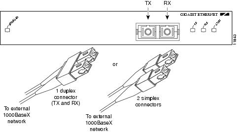
Step 1 ![]() Attach the appropriate optical fiber cable directly to the SC-type receptacle on the GBIC. (See Figure 4-1.) Use a cable with either one duplex SC-type connector or two simplex SC-type connectors.
Attach the appropriate optical fiber cable directly to the SC-type receptacle on the GBIC. (See Figure 4-1.) Use a cable with either one duplex SC-type connector or two simplex SC-type connectors.
Figure 4-1 Attaching Multimode or Single-Mode Optical Fiber Cables to a GBIC—Horizontal Orientation Shown

Warning ![]() Invisible laser radiation may be emitted from disconnected fibers or connectors. Do not stare into beams or view directly with optical instruments. Statement 105
Invisible laser radiation may be emitted from disconnected fibers or connectors. Do not stare into beams or view directly with optical instruments. Statement 105
Warning ![]() Class 1 laser product. Statement 1008
Class 1 laser product. Statement 1008
Step 2 ![]() Attach the network ends of your optical fiber cables to the 1000BASE-X equipment in your cable plant.
Attach the network ends of your optical fiber cables to the 1000BASE-X equipment in your cable plant.
This completes the procedure for attaching optical fiber cable to your GBIC.
Attaching a Mode Conditioning Patch Cord to a GBIC-LX or GBIC-LH
This section describes the procedure for attaching a mode conditioning patch cord to your GBIC-LX or GBIC-LH when you expect transmission distances to be greater than 984.25 feet (300 meters) over 50/125-micron or 62.5/125-micron multimode fiber. The mode conditioning patch cord is available from Cisco Systems as Product Number CAB-GELX-625=. (For specific information about the mode conditioning patch cord, see the "Mode Conditioning Patch Cord with a Multimode GBIC-LX and GBIC-LH" section on page 1-10.)
Note ![]() If you use a GBIC-LX or GBIC-LH with single-mode optical fiber connections, you do not need to use the mode conditioning patch cord; therefore, proceed to the "Attaching Multimode and Single-Mode Optical Fiber Cables to a GBIC" section.
If you use a GBIC-LX or GBIC-LH with single-mode optical fiber connections, you do not need to use the mode conditioning patch cord; therefore, proceed to the "Attaching Multimode and Single-Mode Optical Fiber Cables to a GBIC" section.
The network end of the GBIC has a duplex SC-type receptacle. You must attach the mode conditioning patch cord to the SC-type receptacle on your GBIC (the Gigabit Ethernet interface).
Use the following procedure to attach the mode conditioning patch cord to your GBIC:
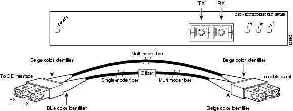
Step 1 ![]() Attach the mode conditioning patch cord to the SC-type receptacle on the GBIC. (See Figure 4-2.)
Attach the mode conditioning patch cord to the SC-type receptacle on the GBIC. (See Figure 4-2.)
Figure 4-2 Attaching a Mode Conditioning Patch Cord to a GBIC—Horizontal Orientation Shown
Warning ![]() Invisible laser radiation may be emitted from disconnected fibers or connectors. Do not stare into beams or view directly with optical instruments. Statement 1051
Invisible laser radiation may be emitted from disconnected fibers or connectors. Do not stare into beams or view directly with optical instruments. Statement 1051
Warning ![]() Class 1 laser product. Statement 1008
Class 1 laser product. Statement 1008
Step 2 ![]() Attach the network ends of your mode conditioning patch cord to the appropriate 1000BASE-X equipment in your building cable plant. (See Figure 4-2.)
Attach the network ends of your mode conditioning patch cord to the appropriate 1000BASE-X equipment in your building cable plant. (See Figure 4-2.)
This completes the procedure for attaching a mode conditioning patch cord to your GBIC.
Replacing a GBIC in the PA-GE
Your PA-GE shipped with a GBIC installed, depending on the PA-GE model you ordered (1000BASE-SX, 1000BASE-LX, 1000BASE-LH, or 1000BASE-ZX).
Note ![]() If your PA-GE arrived without the GBIC installed and you need to install it now, or you need to change your GBIC for another reason, use the procedures in this section; otherwise, you do not need to use these procedures.
If your PA-GE arrived without the GBIC installed and you need to install it now, or you need to change your GBIC for another reason, use the procedures in this section; otherwise, you do not need to use these procedures.
Note ![]() If your GBIC is already properly installed, proceed to the "Attaching Multimode and Single-Mode Optical Fiber Cables to a GBIC" section; otherwise, continue with the following procedures.
If your GBIC is already properly installed, proceed to the "Attaching Multimode and Single-Mode Optical Fiber Cables to a GBIC" section; otherwise, continue with the following procedures.
Note ![]() You can install and remove GBICs with power on to the system; however, we strongly recommend that you do not install or remove the GBIC with optical fiber cables attached to it. Disconnect all cables before removing or installing a GBIC.
You can install and remove GBICs with power on to the system; however, we strongly recommend that you do not install or remove the GBIC with optical fiber cables attached to it. Disconnect all cables before removing or installing a GBIC.
Removing a GBIC from the PA-GE
Use the following procedure to remove a GBIC from your PA-GE:
Step 1 ![]() Attach an ESD-preventive wrist strap between you and an unpainted chassis surface.
Attach an ESD-preventive wrist strap between you and an unpainted chassis surface.
Step 2 ![]() Disconnect the SC-type optical fiber cables or the mode conditioning patch cord from the GBIC; note which plug is TX and which plug is RX for reattachment.
Disconnect the SC-type optical fiber cables or the mode conditioning patch cord from the GBIC; note which plug is TX and which plug is RX for reattachment.
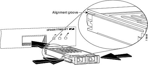
Step 3 ![]() Locate the tabs on either side of the exposed portion of the GBIC and squeeze them with your thumb and forefinger as you gently pull the GBIC out of the GBIC slot. (See arrows in Figure 4-3.)
Locate the tabs on either side of the exposed portion of the GBIC and squeeze them with your thumb and forefinger as you gently pull the GBIC out of the GBIC slot. (See arrows in Figure 4-3.)
Figure 4-3 Removing and Inserting a GBIC
Inserting a GBIC into the PA-GE
Use the following procedure to insert a GBIC into your PA-GE interface:
Step 1 ![]() Attach an ESD-preventive wrist strap between you and an unpainted chassis surface.
Attach an ESD-preventive wrist strap between you and an unpainted chassis surface.
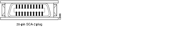
Step 2 ![]() Locate the alignment groove on the GBIC. (See the enlargement in Figure 4-3.) Position the GBIC so that this groove is in the position shown in the enlargement, to ensure that the 20-pin plug on the GBIC is in the correct position.
Locate the alignment groove on the GBIC. (See the enlargement in Figure 4-3.) Position the GBIC so that this groove is in the position shown in the enlargement, to ensure that the 20-pin plug on the GBIC is in the correct position.
Figure 4-4 20-Pin Plug on the GBIC
Step 3 ![]() Squeeze the tabs on each side of the GBIC using your thumb and forefinger, and insert the GBIC into the GBIC slot on the PA-GE. (See Figure 4-3.)
Squeeze the tabs on each side of the GBIC using your thumb and forefinger, and insert the GBIC into the GBIC slot on the PA-GE. (See Figure 4-3.)
Step 4 ![]() Using moderate force, ensure that the GBIC is fully inserted into the 20-pin receptacle at the rear of the GBIC slot. The tabs on either side of the GBIC snap into place when you have completely and properly inserted the GBIC.
Using moderate force, ensure that the GBIC is fully inserted into the 20-pin receptacle at the rear of the GBIC slot. The tabs on either side of the GBIC snap into place when you have completely and properly inserted the GBIC.
Step 5 ![]() Reattach the SC-type optical fiber cable or the mode conditioning patch cord to the GBIC. (Use the appropriate procedure in the "Connecting Cables to the PA-GE" section.)
Reattach the SC-type optical fiber cable or the mode conditioning patch cord to the GBIC. (Use the appropriate procedure in the "Connecting Cables to the PA-GE" section.)
This completes the procedures for replacing the GBIC in your PA-GE interface.
 Feedback