Configuring the Cisco Catalyst C9300L-48P-4X-A Switches
This section provides a detailed procedure for configuring the Cisco Catalyst C9300L-48P-4X-A for use in a HyperFlex SD-WAN environment. Follow these steps precisely because failure to do so could result in an improper configuration. The deployment of the switches is in standalone mode.
Network Switch Configuration
No switch stacking is used in this configuration. The 10GbE connections on the server are connected to port 1 (to switch A) and port 3 (to switch B) of the Cisco VIC 1457 mLOM on each server.
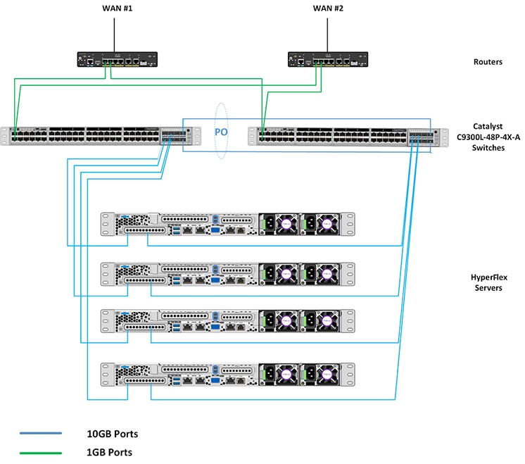
Physical Connectivity
HyperFlex SD-WAN Catalyst CablingThe following tables provide the details of all the physical connections used by HyperFlex and the networking requirements for the SD-WAN solution.
Cisco Catalyst C9300L-48P-4X-A Cabling Information|
Local Device |
Local Port |
Connection |
Remote Device |
Remote Port |
|---|---|---|---|---|
|
Cisco Catalyst 9300-A |
TenGig1/1/1 |
10 GbE |
UCSM5-Edge-Node1 |
VIC1 |
|
Cisco Catalyst 9300-A |
TenGig1/1/2 |
10 GbE |
UCSM5-Edge-Node2 |
VIC1 |
|
Cisco Catalyst 9300-A |
TenGig1/1/3 |
10 GbE |
UCSM5-Edge-Node3 |
VIC1 |
|
Cisco Catalyst 9300-A |
TenGig1/1/4 |
10 GbE |
UCSM5-Edge-Node4 |
VIC1 |
|
Cross Link 1 |
TenGig1/1/7 |
10 GbE |
Cisco Catalyst 9300-B |
TenGig 1/1/7 |
|
Cross Link 2 |
TenGig1/1/8 |
10 GbE |
Cisco Catalyst 9300-B |
TenGig 1/1/8 |
|
ISP #1 Link 1 |
GigEth1/0/1 |
1 GbE |
Physical Router A |
N/A |
|
ISP #2 Link 1 |
GigEth1/0/2 |
1 GbE |
Physical Router B |
N/A |
|
MGMT0 |
SVI |
Management IP |
SVI |
|
Local Device |
Local Port |
Connection |
Remote Device |
Remote Port |
|---|---|---|---|---|
|
Cisco Catalyst 9300-B |
TenGig1/1/1 |
10 GbE |
UCSM5-Edge-Node1 |
VIC2 |
|
Cisco Catalyst 9300-B |
TenGig1/1/2 |
10 GbE |
UCSM5-Edge-Node2 |
VIC2 |
|
Cisco Catalyst 9300-B |
TenGig1/1/3 |
10 GbE |
UCSM5-Edge-Node3 |
VIC2 |
|
Cisco Catalyst 9300-B |
TenGig1/1/4 |
10 GbE |
UCSM5-Edge-Node4 |
VIC2 |
|
Cross Link 1 |
TenGig1/1/7 |
10 GbE |
Cisco Catalyst 9300-A |
TenGig 1/1/7 |
|
Cross Link 2 |
TenGig1/1/8 |
10 GbE |
Cisco Catalyst 9300-A |
TenGig 1/1/8 |
|
ISP #1 Link 2 |
GigEth1/0/1 |
1 GbE |
Physical Router A |
N/A |
|
ISP #2 Link 2 |
GigEth1/0/2 |
1 GbE |
Physical Router B |
N/A |
|
MGMT0 |
SVI |
Management IP |
SVI |
HyperFlex SD-WAN Necessary VLANs
The following table shows an example of how to define the VLAN IDs. You can define the VLAN IDs depending on your network requirements.
|
VLAN Name |
VLAN Purpose |
Example ID |
|---|---|---|
|
Intranet-MGMT |
Management traffic among CIMC In-Band IP address, ESXi management IP address, HyperFlex management IP address. CIMC VLAN (Can be same or different from the Management VLAN). |
100 |
|
HyperFlex Storage |
VLAN to serve storage traffic, requires only L2 connectivity. |
31 |
|
HyperFlex vMotion |
VLAN for vMotion VLAN, if applicable. |
32 |
|
VM-Network |
VLAN/VLANs for VM/application network. |
33 |
|
WAN #1 |
VLAN for ISP1 |
11 |
|
WAN #2 |
VLAN for ISP2 |
12 |
Initial Setup For Cisco Catalyst C9300L-48P-4X-A Switches
The following sections provide an initial setup procedure for Cisco Catalyst C9300L-48P-4X-A/B Switches.
 Attention |
This procedure assumes the use of a pair of Cisco Catalyst C9300L-48P-4X-A switches running vEdge version 17.1 or higher. |
To set up the initial configuration for the Cisco Catalyst C9300L-48P-4X-A switches, complete the following steps on both switch A and Switch B:
Cisco Catalyst 9300L Switch A/B Initial Configurationshow running-config
!
hostname Selvan-Cat9k-A
!
!
vrf definition HX-MGMT
!
!
ip routing
!
ip name-server vrf HX-MGMT 8.8.8.8
ip domain name cat9k
!
!
system mtu 9000
license boot level network-advantage addon dna-advantage
!
interface Port-channel1
description " cross-link-to-SDWAN-A/B-switch"
switchport trunk allowed vlan 11-12,31,100,200
switchport mode trunk
!
interface GigabitEthernet0/0
description “Mgmt interface for switch”
vrf forwarding Mgmt-vrf
ip address 10.193.232.83 255.255.255.0
negotiation auto
!
interface GigabitEthernet1/0/1
description “ISP #1 Link 1/2”
switchport access vlan 11
switchport mode access
!
interface GigabitEthernet1/0/2
description “ISP #2 Link 1/2”
switchport access vlan 12
switchport mode access
!
interface GigabitEthernet1/0/7
description “Member of port channel 1”
switchport trunk allowed vlan 11-12,31,100,200
switchport mode trunk
mtu 9000
channel-group 1 mode active
!
interface GigabitEthernet1/0/8
description “Member of port channel 1”
switchport trunk allowed vlan 11-12,31,100,200
switchport mode trunk
mtu 9000
channel-group 1 mode active
!
interface TenGigabitEthernet1/1/1
description “CIMC port for node-1”
switchport trunk allowed vlan 11,12 ,31,100,200
switchport mode trunk
mtu 9000
!
interface TenGigabitEthernet1/1/2
description “CIMC port for node-2”
switchport trunk allowed vlan 11,12,31,100,200
switchport mode trunk
mtu 9000
!
interface Vlan11
description VLAN for WAN1
vrf forwarding HX-MGMT
ip address 192.168.11.252 255.255.255.0
ip nat outside
!
interface Vlan12
description VLAN for WAN2
vrf forwarding HX-MGMT
ip address 192.168.12.252 255.255.255.0
ip nat outside
!
interface Vlan100
description "Default GW for DC & Cimc"
vrf forwarding HX-MGMT
ip address 192.168.100.252 255.255.255.0
ip nat inside
standby version 2
standby 10 ip 192.168.100.254
standby 10 priority 110
standby 10 preempt
!
interface Vlan200
description vlan for vedge
vrf forwarding HX-MGMT
ip address 192.168.200.252 255.255.255.0
standby version 2
standby 10 ip 192.168.200.254
standby 10 priority 110
standby 10 preempt
!
ip forward-protocol nd
ip http server
ip http authentication local
ip http secure-server
ip nat pool nat-232 10.193.232.111 10.193.232.114 netmask 255.255.255.0
ip nat inside source route-map ViaVlan11 interface Vlan11 vrf HX-MGMT overload
ip nat inside source route-map ViaVlan12 interface Vlan12 vrf HX-MGMT overload
ip nat inside source list 1 pool nat-232
ip route vrf HX-MGMT 0.0.0.0 0.0.0.0 192.168.11.254
ip route vrf HX-MGMT 192.168.61.0 255.255.255.0 192.168.200.1
!
ip access-list standard 1
20 permit 192.168.100.0 0.0.0.255
!
route-map ViaVlan12 permit 10
match ip address 1
match interface Vlan12
!
route-map ViaVlan11 permit 10
match ip address 1
match interface Vlan11
!Attention |
Post-deployment remove ip route vrf HX-MGMT 0.0.0.00.0.0.0192.168.11.254 and ip route vrf HX-MGMT 192.168.61.0255.255.255.0192.168.200.1. Replace it with ip route vrf HX-MGMT 0.0.0.00.0.0.0192.168.200.1. |
 Feedback