Network Management

Network Design

Physical Network

Cisco UCS Uplink Connectivity

Cisco UCS network uplinks connect northbound from the pair of UCS Fabric Interconnects (FIs) to the LAN in the customer datacenter. All UCS uplinks operate as trunks, carrying multiple 802.1Q VLAN IDs across the uplinks. By default, the UCS software assumes that all VLAN IDs defined in the UCS configuration are eligible to trunk across all available uplinks.

Figure 1. Logical Network Design

Cisco FIs appear on the network as a collection of endpoints versus another network switch. Internally, the FIs do not participate in spanning-tree protocol (STP) domains, and the FIs cannot form a network loop, as they are not connected to each other with a layer 2 Ethernet link. The upstream root bridges make all link up/down decisions through STP.

Uplinks need to be connected and active from both FIs. For redundancy, you can use multiple uplinks on each FI, either as 802.3ad Link Aggregation Control Protocol (LACP) port-channels or using individual links. For the best level of performance and redundancy, make uplinks as LACP port-channels to multiple upstream Cisco switches using the virtual port channel (vPC) feature. Using vPC uplinks allows all uplinks to be active passing data, plus protects against any individual link failure and the failure of an upstream switch. Other uplink configurations can be redundant, but spanning-tree protocol loop avoidance may disable links if vPC is unavailable.

All uplink connectivity methods must allow for traffic to pass from one FI to the other, or from fabric A to fabric B. Scenarios can occur where cable, port, or link failures require traffic that normally does not leave the UCS domain to now be forced over the UCS uplinks. In addition, you can briefly see this traffic flow pattern maintenance procedures, such as during firmware updates on the FI, which requires them to be rebooted.

VLANs and Subnets

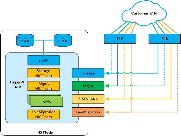
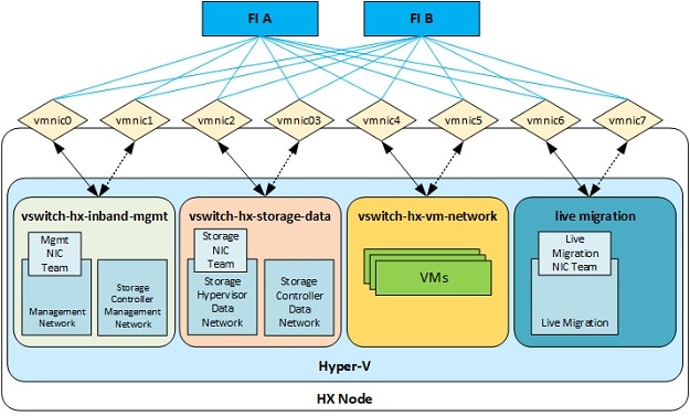
For a Cisco HyperFlex system configuration, you must carry multiple VLANs to the UCS domain from the upstream LAN. You define these VLANs in the UCS configuration.

Table 1. HyperFlex Installer-Created VLANs
VLAN Name

VLAN ID

Purpose

hx-inband-mgmt

Customer supplied

Hyper-V host management interfaces

HX Storage Controller VM management interfaces

HX Storage Cluster roaming management interface

hx-storage-data

Customer supplied

Hyper-V host storage vmkernel interfaces

HX Storage Controller storage network interfaces

HX Storage Cluster roaming storage interface

hx-vm-data

Customer supplied

Guest VM network interfaces

hv-livemigration

Customer supplied

Hyper-V host Live Migration vmkernel interface


Note

Datacenters often use a dedicated network or subnet for physical device management. In this scenario, the mgmt0 interfaces of the two FIs must connect to that dedicated network or subnet. HyperFlex installations consider this a valid configuration with the following caveat: you must deploy the HyperFlex installer in a location where it has IP connectivity to the following subnets:

  • Subnet of the mgmt0 interfaces of the FIs

  • Subnets used by the hx-inband-mgmt VLANs previously listed


Jumbo Frames

Configure all Cisco HyperFlex storage traffic that traverses the hx-storage-data VLAN and subnet to use jumbo frames; that means you configure all communication to send IP packets with a Maximum Transmission Unit (MTU) size of 9000 bytes. When you use a larger MTU value, each IP packet sent carries a larger payload, so it transmits more data per packet, and consequently sends and receives data faster. This requirement also means that you must configure the Cisco UCS uplinks to pass jumbo frames. Failure to configure the Cisco UCS uplink switches to allow jumbo frames can lead to service interruptions during some failure scenarios, particularly when cable or port failures cause storage traffic to traverse the northbound Cisco UCS uplink switches.

Logical Network

The Cisco HyperFlex system has communication pathways that fall into the following defined zones:

Table 2. Defined Communication Pathway Zones

Zone

Description

Management Zone

Comprises the connections needed to manage the physical hardware, the hypervisor hosts, and the storage platform controller virtual machines (SCVM). Make these interfaces and IP addresses available to all staff who will administer the HX system, throughout the LAN/WAN. This zone must provide access to Domain Name System (DNS) and Network Time Protocol (NTP) services, and allow Secure Shell (SSH) communication.

VM Zone

Comprises the connections needed to service network IO to the guest VMs that run inside the HyperFlex hyperconverged system. This zone typically contains multiple VLANs that are trunked to the Cisco UCS Fabric Interconnects (FIs) through the network uplinks and tagged with 802.1Q VLAN IDs. Make these interfaces and IP addresses available to all staff and other computer endpoints that need to communicate with the guest VMs in the HX system, throughout the LAN/WAN.

Storage Zone

Comprises the connections used by the Cisco HX Data Platform software, Hyper-V hosts, and the storage controller VMs to service the HX Distributed Data Filesystem. These interfaces and IP addresses must be able to communicate with each other at all times for proper operation. During normal operation, this traffic all occurs within the UCS domain; however, there are hardware failure scenarios where this traffic needs to traverse the network northbound of the Cisco UCS domain. For that reason, the VLAN used for HX storage traffic must be able to traverse the network uplinks from the UCS domain, reaching FI A from FI B, and vice-versa. This zone contains primarily jumbo frame traffic, so jumbo frames must be enabled on the UCS uplinks.

Live Migration Zone

Comprises the connections used by the Hyper-V hosts to enable Live Migration of the guest VMs from host to host. During normal operation, this traffic all occurs within the Cisco UCS domain; however, there are hardware failure scenarios where this traffic needs to traverse the network northbound of the Cisco UCS domain. For that reason, the VLAN used for HX storage traffic must be able to traverse the network uplinks from the Cisco UCS domain, reaching FI A from FI B, and vice-versa.

Virtual Network

The Cisco HyperFlex system has a pre-defined virtual network design at the hypervisor level. The HyperFlex installer creates four different virtual switches (vSwitches). Each switch uses two uplinks, which are each serviced by a vNIC defined in the Cisco UCS service profile.

Figure 2. Hyper-V Network Design
Table 3. Installer-Created vSwitches

vSwitches

Description

vswitch-hx-inband-mgmt

Default vSwitch0. Renamed by the Hyper-V kickstart file as part of the automated installation. The installer configures the default vmkernel port, vmk0, in the standard Management Network port group. The switch has two uplinks, active on fabric A and standby on fabric B, without jumbo frames. The installer also creates a second port group for the Storage Platform Controller VMs to connect to with their individual management interfaces. The VLAN is not a Native VLAN as assigned to the vNIC template, and therefore assigned in Hyper-V.

vswitch-hx-storage-data

Created as part of the automated installation. The installer configures a vmkernel port in the Storage Hypervisor Data Network port group. The system uses the interface for connectivity to the HX Datastores through NFS. The switch has two uplinks, active on fabric B and standby on fabric A, with jumbo frames required. The installer also creates a second port for the Storage Platform Controller VMs to connect to with their individual storage interfaces. The VLAN is not a Native VLAN as assigned to the vNIC template, and therefore assigned in Hyper-V.

vswitch-hx-vm-network

Created as part of the automated installation. The switch has two uplinks, active on both fabrics A and B, and without jumbo frames. The VLAN is not a Native VLAN as assigned to the vNIC template, and therefore assigned in Hyper-V.

vswitch-hx-livemigration

Created as part of the automated installation. The switch has two uplinks, active on fabric A and standby on fabric B, with jumbo frames required. The VLAN is not a Native VLAN as assigned to the vNIC template, and therefore assigned in Hyper-V.

Network Configuration after Cluster Setup

Creating a QoS Policy

A quality of service (QoS) policy assigns a system class to the outgoing traffic for a vNIC or vHBA. This system class determines the quality of service for that traffic.

You must include a QoS policy in a vNIC policy or vHBA policy, and then include that policy in a service profile to configure the vNIC or vHBA.

You can configure the system classes shown in the following table:

Table 4. System Classes

System Class

Description

Platinum

Gold

Silver

Bronze

Configurable set of system classes that you can include in the QoS policy for a service profile. Each system class manages one lane of traffic.

All properties of these system classes are available for you to assign custom settings and policies.

Best Effort

Sets the quality of service for the lane reserved for basic Ethernet traffic.

Some properties of this system class are preset and cannot be modified. For example, this class has a drop policy that allows it to drop data packets if required. You cannot disable this system class.

Fibre Channel

Sets the quality of service for the lane reserved for Fibre Channel over Ethernet traffic.

Some properties of this system class are preset and cannot be modified. For example, this class has a no-drop policy that ensures it never drops data packets. You cannot disable this system class.

Note 

FCoE traffic has a reserved QoS system class that should not be used by any other type of traffic. If any other type of traffic has a CoS value that is used by FCoE, the value is remarked to 0.

To create a QoS Policy in UCS Manager, perform the following steps:

Procedure


Step 1

Open a web browser and enter the IP address for Cisco UCS Manager. Enter the login credentials.

Step 2

In the Navigation pane, click LAN.

Step 3

In the LAN tab, expand LAN > Policies.

Step 4

Expand the root node > Sub-org > hx-cluster

Step 5

Right-click QoS Policy and select Create QoS Policy.

Step 6

In the Create QoS Policy dialog, complete the fields for your systems class as shown in the following table:

QoS Policy Name

QoS Class

Burst Size

Rate

Host Control

Platinum

Platinum

10240

Line-rate

none

Gold

Gold

10240

Line-rate

none

Silver

Silver

10240

Line-rate

none

Bronze

Bronze

10240

Line-rate

none

Best Effort

Best Effort

10240

Line-rate

none

Step 7

Click OK.


What to do next

Include the QoS policy in a vNIC or vHBA template.

Creating MAC Address Pools

You can change the default MAC address blocks to avoid duplicate MAC addresses that may already exist. Each block contains 100 MAC addresses by default to allow for up to 100 HX servers for deployment per UCS system. We recommend that you use one MAC pool per vNIC for easier troubleshooting.


Note

The 8th digit is set to either A or B. The A is set on vNICs pinned to Fabric Interconnect (FI) A. The B is set on vNICs pinned to FI B.

Procedure


Step 1

Open a web browser and enter the IP address for Cisco UCS Manager. Enter the login credentials.

Step 2

In Cisco UCS Manager, navigate to LAN tab > Pools > root > Sub-org > hx-cluster > MAC Pools.

Step 3

Right-click MAC Pools and select Create MAC Pool.

Step 4

In the Define Name and Description page of the Create MAC Pool wizard, complete the required fields as shown in the following table:

MAC Pool Name

Description

Assignment Order

MAC Address block

hv-mgmt-a

MAC pool for HyperFlex System

Sequential

00:25:B5:XX:01:01-64

hv-mgmt-b

MAC pool for HyperFlex System

Sequential

00:25:B5:XX:02:01-64

storage-data-a

MAC pool for HyperFlex System

Sequential

00:25:B5:XX:03:01-64

storage-data-b

MAC pool for HyperFlex System

Sequential

00:25:B5:XX:04:01-64

vm-network-a

MAC pool for HyperFlex System

Sequential

00:25:B5:XX:05:01-64

vm-network-b

MAC pool for HyperFlex System

Sequential

00:25:B5:XX:06:01-64

hv-livemigration-a

MAC pool for HyperFlex System

Sequential

00:25:B5:XX:07:01-64

hv-livemigration-b

MAC pool for HyperFlex System

Sequential

00:25:B5:XX:08:01-64

Step 5

Click Next.

Step 6

In the Add MAC Addresses page of the Create MAC Pool wizard, click Add.

Step 7

In the Create a Block of MAC Addresses dialog box, complete the following fields:

Name Description

First MAC Address field

The first MAC address in the block.

Size field

The number of MAC addresses in the block.

Step 8

Click OK.

Step 9

Click Finish.

After the MAC address change, the software reconfigures Hyper-V to how it was configured earlier. But, if management IP was DHCP assigned, then the IP changes.

Impact of Manufacturing process on MAC address change

  • The MAC address will change between the manufacturing process and the customer site, especially if the customer orders HyperFlex serves without UCS Fabric Interconnects.

  • A MAC address is configured during Service Profile association. It is un-configured during Service Profile disassociation.

  • At the end of manufacturing process, the service profiles are disassociated, hence the MAC addresses are un-configured.

  • When a HyperFlex server is deployed, configure the MAC address pools as described earlier.


Creating VLANs for HX Servers

Procedure


Step 1

Open a web browser and enter the IP address for Cisco UCS Manager. Enter the login credentials.

Step 2

Navigate to LAN tab > LAN > LAN Cloud > VLANS.

Step 3

Right-click and select Create VLANs as shown in the table below:

VLAN Name

Description

Multicast Policy Name

VLAN ID (by default)

hx-inband-mgmt

Used for:

  • Hyper-V management

  • SSH to storage controller VM

  • HX Cluster management IP - using multicast traffic.

  • Hyper-V Manager connectivity to the HyperFlex VM for the HX Data Platform plug-in

HyperFlex

3091

hx-storage-data

Used for:

  • Hyper-V NFS client (IOvisor)

  • HyperFlex replication/cluster

  • Cluster data VIP

HyperFlex

3092

hx-livemigration

Used for:

  • VM and storage livemigration, FT, iSCSI

HyperFlex

3093

insert existing vlan name

Used for:

  • VM data traffic

HyperFlex

Any*

Note 
  • Configuration option is Common/Global. It applies to both fabrics and uses the same configuration parameters in both cases.

  • *There is no specific recommendation for VM data VLANs. You can create your own VLANs for the VM data traffic. By default, the HXDP installer will not create VLANs for the VM data traffic.


Creating vNIC Templates for HX Servers

Before you begin

This policy requires that one or more of the following resources already exist in the system:

  • Named VLAN

  • MAC pool

  • QoS policy

  • LAN pin group

  • Statistics threshold policy

In this procedure you create a total of eight vNIC templates: one each for the traffic management, storage management, Network Management, LiveMigration for FI(A) and same set for FI(B)

Procedure


Step 1

In Cisco UCS Manager, navigate to LAN tab > Policies > root > Sub-Organization > Hyperflex > vNIC Templates.

Step 2

Right-click the vNIC Templates node and select Create vNIC Template.

Step 3

In the Create Network Policy dialog box, complete the required fields as follows:

vNIC Template Name

Fabric ID

VLAN

Native VLAN

MAC address Pool

MTU

QoS Policy

Network Control Policy

Description

hv-mgmt-a

A

hx-inband-mgmt

Yes

hv-mgmt-a

1500

Silver

Network Control Policy: hyperflex-infra

Used for:

  • ESX management

  • SSH to storage controller VM

  • Cluster management IP

  • Hyper-V manager connectivity to the HX Controller VM for the HXDP plug-in

  • hv-mgmt-a and hv-mgmt-b are used as uplinks for virtual switch vswitch-hx-inband-mgmt in Hyper-V manager

hv-mgmt-b

B

hx-inband-mgmt

Yes

hv-mgmt-b

storage-data-a

A

storage-data

Yes

storage-data-a

9000

Platinum

Network Control Policy: hyperflex-infra

Used for:

  • Hyper-V NFS client (IOSvisor)

  • HXDP replication/cluster

  • Cluster data VIP

  • storage-data-a and storage-data-b are used as uplinks for virtual switch vswitch-hx-storage-data in Hyper-V manager

  • NFS traffic should be on a dedicated vNIC and VLAN due to security and QoS considerations

storage-data-b

B

storage-data

Yes

storage-data-b

vm-network-a

A

(customer vlan name)

Yes

vm-network-a

1500

Gold

Network Control Policy: hyperflex-vm

Used for:

  • VM data traffic (VDI, database, and such)

  • vm-network-a and vm-network-b are used as uplinks for virtual switch vswitch-hx-vm-network in Hyper-V manager

vm-network-b

B

(customer VLAN name)

Yes

vm-network-b

hv-livemigration-a

A

hv-motion-a

Yes

hv-livemigration-a

9000

Bronze

Network Control Policy: hyperflex-infra

Used for:

  • VM and storage LiveMigration, FT

  • hv-livemigration-a and hv-livemigration-b are used as uplinks for virtual switch LiveMigration in Hyper-V manager

hv-livemigration-b

B

hv-motion-b

Yes

hv-livemigration-a

In the General area, set all the properties according to the following reference table across all the eight of the vNICs:

Failover

Disabled

Target

Adapter

Template Type

Updating

Pin Group

not set

Stats Threshold Policy

default

Dynamic vNIC Connection Policy

not set

VLANs

Configure as shown in the following table for each of the vNIC templates.

Table 5. Configured VLANs on the vNIC templates

vNIC Name

VLANs

Comments

hv-mgmt-a

hx-inband-mgmt

The HXDP Installer configures a single VLAN on the UCSM LCP vNIC as follows:

  • Set the VLAN name to hx-inband-mgmt

  • Set as the native VLAN

  • Set the VLAN ID to 3091 by default

    Note 
    You can change the VLAN ID in the HXDP Installer
  • Post HXDP install, you can open UCSM and create more VLANs to add to the hv-mgmt-a and hv-mgmt-b vNIC templates

    Note 
    You can use these additional VLANs to access external systems, such as NetApp NFS/ISCSI filer.
  • Port Group name is Storage Controller Management network backed by VLAN hx-inband-mgmt

hv-mgmt-b

storage-data-a

hx-storage-data

The HXDP Installer configures a single VLAN as follows:

  • Set the VLAN name to hx-storage-data

  • Set as the native VLAN

  • Set the VLAN ID to 3092 by default

    Note 
    You can change the VLAN id in the HXDP Installer, but it cannot be the same as hx-inband-mgmt, or the Hyper-V routing will get confused.
  • Port Group names are:

    • Storage Controller Data Network backed by VLAN hx-storage-data

    • VMK Storage Hypervisor Data Network backed by VLAN hx-storage-data

  • Subnet 10

storage-data-b

vm-network-a

user created VLANs

  • Manually create one or more VLANs in UCSM

  • Manually create port groups backed by user-created VLANs

  • You can create more VLANs in UCSM and assign them to the vm-network-a and vm-network-b vNIC templates for VM traffic

    Note 
    The HXDP Installer does not configure any VLAN or Port group.

vm-network-b

hv-livemigration-a

hv-livemigration

The HXDP Installer configures a single VLAN as follows:

  • LiveMigration: VLAN hv-livemigration-

  • Set the VLAN ID

  • Sets as the native VLAN

  • VLAN ID is 3093 by default

  • Subnet 10

hv-livemigration-b

Step 4

Click OK when finished.


About Private VLAN

A private VLAN partitions the Layer 2 broadcast domain of a VLAN into subdomains, allowing you to isolate the ports on the switch from each other. A subdomain consists of a primary VLAN and one or more secondary VLANs. A private VLAN domain has only one primary VLAN. Each port in a private VLAN domain is a member of the primary VLAN, and the primary VLAN is the entire private VLAN domain.

Understanding Private VLAN Ports

The types of private VLAN ports are as follows:

  • Promiscuous Primary VLAN — A promiscuous port belongs to the primary VLAN. The promiscuous port can communicate with all interfaces, including the community and isolated host ports, that belong to those secondary VLANs associated to the promiscuous port and associated with the primary VLAN. All packets from the secondary VLANs go through this VLAN.

  • Isolated Secondary VLAN — An isolated port is a host port that belongs to an isolated secondary VLAN. This port has complete isolation from other ports within the same private VLAN domain, except that it can communicate with associated promiscuous ports.

  • Community Secondary VLAN — A community port is a host port that belongs to a community secondary VLAN. Community ports communicate with other ports in the same community VLAN and with associated promiscuous ports.

By default, after HX deployment, a VM network uses regular VLAN.

Reset Stats Daemon

Description

A network daemon listens for statistics, like counters and timers, sent over UDP or TCP and sends aggregates to one or more pluggable backend services.

After manually re-installing Hyper-V on your HX Data Platform servers, reset the stats daemon to ensure performance statistics display correctly.

Action: restart stats daemon

Procedure


Step 1

Login to the command line of the controller VM of the Hyper-V host.

Step 2

Run the restart command.

# /etc/init.d/statsd restart

Step 3

Repeat Step 1 and Step 2 on the controller VM of every Hyper-V host in the storage cluster.