External Storage Management

Understanding External Storage Management

A Cisco HyperFlex System provides consolidated access to both SAN storage and Network Attached Storage (NAS) over the unified fabric. By unifying storage access, a Cisco Unified Computing System can access storage over Ethernet, Fibre Channel, Fibre Channel over Ethernet (FCoE), and iSCSI.

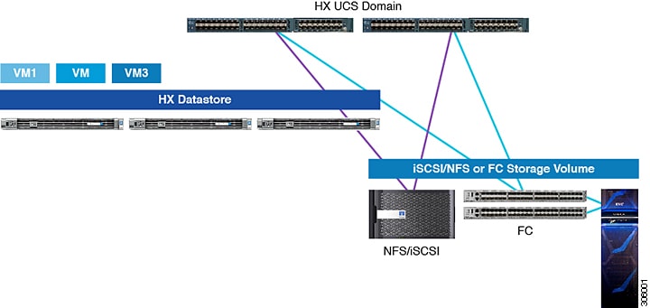
The following image depicts a Cisco HyperFlex System integrated with external storage.

Figure 1. Integrating External Storage with Cisco HyperFlex Systems

External Fibre Channel Storage

Fibre Channel Zoning

Fibre Channel (FC) zoning allows you to partition the FC fabric into one or more zones. Each zone defines the set of FC initiators and FC targets that can communicate with each other in a VSAN. Zoning also enables you to set up access control between hosts and storage devices or user groups.

Information About Zones

A zone consists of multiple zone members and has the following characteristics:

  • Members in a zone can access each other; members in different zones cannot access each other.

  • Zones can vary in size.

  • Devices can belong to more than one zone.

A physical fabric can have a maximum of 8,000 zones.

Fibre Channel Zoning in Cisco UCS Manager

Cisco UCS Manager supports switch-based Fibre Channel (FC) zoning and Cisco UCS Manager-based FC zoning. You cannot configure a combination of zoning types in the same Cisco UCS domain. You can configure a Cisco UCS domain with one of the following types of zoning:

  • Cisco UCS Manager-based Fibre Channel zoning — This configuration combines direct attach storage with local zoning. Fibre Channel or FCoE storage is directly connected to the fabric interconnects and zoning is performed in Cisco UCS Manager, using Cisco UCS local zoning. Any existing Fibre Channel or FCoE uplink connections need to be disabled. Cisco UCS does not currently support active Fibre Channel or FCoE uplink connections coexisting with the utilization of the Cisco UCS Local Zoning feature.

  • Switch-based Fibre Channel zoning — This configuration combines direct attach storage with uplink zoning. The Fibre Channel or FCoE storage is directly connected to the fabric interconnects and zoning is performed externally to the Cisco UCS domain through an MDS or Nexus 5000 switch. This configuration does not support local zoning in the Cisco UCS domain. With switch-based zoning, a Cisco UCS domain inherits the zoning configuration from the upstream switch.


Note

Zoning is configured on a per-VSAN basis. You cannot enable zoning at the fabric level.


Recommendations

  • If you want Cisco UCS Manager to handle Fibre Channel zoning, the fabric interconnects must be in Fibre Channel Switch mode. You cannot configure Fibre Channel zoning in End-Host mode.

  • If a Cisco UCS domain is configured for high availability with two fabric interconnects, we recommend that both fabric interconnects are configured with the same set of VSANs.

Configuring Fibre Channel Zoning

Procedure


Step 1

If you have not already done so, disconnect the fabric interconnects in the Cisco UCS domain from any external Fibre Channel switches, such as an MDS.

Step 2

If the Cisco UCS domain still includes zones that were managed by the external Fibre Channel switch, run the clear-unmanaged-fc-zone-all command on every affected VSAN to remove those zones.

This functionality is not currently available in the Cisco UCS Manager GUI. You must perform this step in the Cisco UCS Manager CLI.

Step 3

Configure the Fibre Channel switching mode for both fabric interconnects in Fibre Channel Switch mode.

You cannot configure Fibre Channel zoning in End-Host mode. See http://www.cisco.com/c/en/us/td/docs/unified_computing/ucs/ucs-manager/GUI-User-Guides/Storage-Mgmt/3-1/b_UCSM_GUI_Storage_Management_Guide_3_1/b_UCSM_GUI_Storage_Management_Guide_3_1_chapter_01110.html#task_B6E0C2A15FE84D498503ADC19CDB160B

Step 4

Configure the Fibre Channel and FCoE storage ports that you require to carry traffic for the Fibre Channel zones.

See Configuring an Ethernet Port as an FCoE Storage Port and Configuring a Fibre Channel Storage Port. Refer the following link:

http://www.cisco.com/c/en/us/td/docs/unified_computing/ucs/ucs-manager/GUI-User-Guides/Storage-Mgmt/3-1/b_UCSM_GUI_Storage_Management_Guide_3_1/b_UCSM_GUI_Storage_Management_Guide_3_1_chapter_01100.html#task_A33D13CA58924EB1AD35EBA473B92625


Direct Attached Storage

A typical Direct Attached Storage (DAS) system is made of a data storage device connected directly to a computer through a host bus adapter (HBA). Between those two points there is no network device (like a switch or router). The main protocols used for DAS connections are ATA, SATA, eSATA, SCSI, SAS, USB, USB 3.0, IEEE 1394 and Fibre Channel.

Cisco UCS Manager allows you to have DAS without the need for a SAN switch to push the zoning configuration. The DAS configuration described assumes that the physical cables are already connected between the storage array ports and the Fabric Interconnects.


Note

VSAN is created in the SAN Cloud tab, even when the storage is directly attached.


Fiber Channel Switching Mode

The Fiber Channel switching mode determines how the fabric interconnect behaves as a switching device between the servers and storage devices. The fabric interconnect operates in either of the following Fiber Channel switching modes:

End-Host Mode

End-host mode allows the fabric interconnect to act as an end host to the connected fiber channel networks, representing all servers (hosts) connected to it through virtual host bus adapters (vHBAs). This behavior is achieved by pinning (either dynamically pinned or hard pinned) vHBAs to Fiber Channel uplink ports, which makes the Fiber Channel ports appear as server ports (N-ports) to the rest of the fabric. When in end-host mode, the fabric interconnect avoids loops by denying uplink ports from receiving traffic from one another.

End-host mode is synonymous with N Port Virtualization (NPV) mode. This mode is the default Fiber Channel Switching mode.


Note

When you enable end-host mode, if a vHBA is hard pinned to an uplink Fiber Channel port and this uplink port goes down, the system cannot re-pin the vHBA, and the vHBA remains down.


Switch Mode

Switch mode is the traditional Fiber Channel switching mode. Switch mode allows the fabric interconnect to connect directly to a storage device. Enabling Fiber Channel switch mode is useful in Pod models where there is no SAN (for example, a single Cisco UCS domain that is connected directly to storage), or where a SAN exists (with an upstream MDS). Switch mode is not the default Fiber Channel switching mode.


Note

In Fiber Channel switch mode, SAN pin groups are irrelevant. Any existing SAN pin groups are ignored.


Configuring Fiber Channel Switching Mode


Important

When you change the Fiber Channel switching mode, Cisco UCS Manager logs you out and restarts the fabric interconnect. For a cluster configuration, Cisco UCS Manager restarts both fabric interconnects simultaneously. The second fabric interconnect can take several minutes to complete the change in Fiber Channel switching mode and become system ready.


When the Fiber Channel switching mode is changed, both Cisco UCS fabric interconnects will reload simultaneously. Reloading of fabric interconnects will cause a system-wide downtime for approximately 10-15 minutes.

Procedure


Step 1

In the Navigation pane, click Equipment.

Step 2

Expand Equipment > Fabric Interconnects > Fabric_Interconnect_Name.

Step 3

In the Work pane, click the General tab.

Step 4

In the Actions area of the General tab, click one of the following links:

  • Set FC Switching Mode

  • Set FC End-Host Mode

    The link for the current mode is dimmed.

Step 5

In the dialog box, click Yes.

Cisco UCS Manager restarts the fabric interconnect, logs you out, and disconnects Cisco UCS Manager GUI.


Connect FC Storage Connection to FI and Configure as a FC Storage Port

In the UCS Manager, perform the following steps:

Procedure


Step 1

In the Navigation pane, click Equipment.

Step 2

Expand Equipment > Fabric Interconnects > Fabric_Interconnect_Name.

Step 3

Click the ports under the FC Port node.

Step 4

Right-click the selected port(s) and choose Configure as FC Storage Port.

Step 5

In the dialog box, click Yes.

Step 6

Click OK.


Creating VSAN for Fibre Channel

FCoE VLANs in the SAN cloud and VLANs in the LAN cloud must have different IDs. Using the same ID results in a critical fault and traffic disruption for all vNICs and uplink ports that use that FCoE VLAN. Ethernet traffic is dropped on any VLAN with an ID that overlaps with an FCoE VLAN ID.

Procedure


Step 1

In the Navigation pane, click SAN.

Step 2

Click the SAN Cloud > VSAN node.

Step 3

Right-click the VSAN node, and select Create Storage VSAN.

Step 4

In the Create VSAN dialog box, complete the following fields:

Name

Description

Name field

The name assigned to the network.

This name can be between 1 and 32 alphanumeric characters. You cannot use spaces or any special characters other than - (hyphen), _ (underscore), : (colon), and . (period), and you cannot change this name after the object is saved.

FC Zoning* field

Select Enable radio button for FC Switch mode. The HX Installer may disable it during the configuration process, verify that it is enabled at the end of the configuration.

Note 

Make sure that the FI is not connected to an upstream switch.

Configuration

Select a configuration for your environment.

  • Click the Common/Global radio button so that VSAN maps to the same VSAN ID in all available fabrics.

  • Click Both Fabrics Configured Differently radio button to create two VSANS, with different IDs for Fabric A and Fabric B.

VSAN ID field

The unique identifier assigned to the network. For FC end-host mode, the range between 3840 to 4079 is also a reserved VSAN ID range.

FCoE VLAN field

The unique identifier assigned to the VLAN used for Fibre Channel connections.

VLAN 4048 is user configurable. However, Cisco UCS Manager uses VLAN 4048 for the following default values. If you want to assign 4048 to a VLAN, you must reconfigure these values.


What to do next

If you need to create a new HX cluster, go to: Configuring External Storage on a New Cluster with HX Installer. If the HX cluster is already created, go to: Configuring External Storage on an Existing Cluster

Configuring External Storage on a New Cluster with HX Installer

If the HX cluster is not yet created, perform the following steps to add vHBA and VSAN with HX Installer.

Procedure


Step 1

In the HX Data Platform installer on the UCSM Configuration page, check the Enable FC Storage option.

Step 2

In the FC Storage box, complete the following fields:

Field Name

Description

Example Value

FC Storage

Check box that indicates if FC Storage should be enabled.

Check the box to enable FC Storage

wWxN Pool

A WWM pool that contains both WW node names and WW Port names. For each fabric interconnect, a WWxN pool is created for WWPN and WWNN.

20:00:25:B5:C2

VSAN A Name

the name of the VSAN for the primary fabric interconnect (FI-A). By default, this is set to hx-ext-storage-fc-a.

hx-ext-storage-fc-a

VSAN A ID

The unique identifier assigned to the network for the primary fabric interconnect (FI-A)

70

VSAN B Name

The name of the VSAN for subordinate fabric interconnect (FI-B)

hx-ext-storage-fc-b

VSAN B ID

The unique identifier assigned to network for subordinate fabric interconnect (FI-B)

70

Step 3

Allow the HX Installer complete the cluster creation.


What to do next

configure Fibre Channel Zoning.

Configuring External Storage on an Existing Cluster

If the HX Cluster is already Created, you may use the following tasks to add vNics and VSAN manually.

Creating WWNN Pools

A World Wide Node Name (WWNN) pool is a World Wide Name (WWN) pool that contains only World Wide Node Names. If you include a pool of WWNNs in a service profile, the software assigns the associated server a WWNN from that pool.


Important

A WWN pool can include only WWNNs or WWPNs in the ranges from 20:00:00:00:00:00:00:00 to 20:FF:FF:FF:FF:FF:FF:FF or from 50:00:00:00:00:00:00:00 to 5F:FF:FF:FF:FF:FF:FF:FF. All other WWN ranges are reserved. To ensure the uniqueness of the Cisco UCS WWNNs and WWPNs in the SAN fabric, it is recommended to use the following WWN prefix for all blocks in a pool: 20:00:00:25:B5:XX:XX:XX


Procedure


Step 1

In the Navigation pane, click SAN.

Step 2

Expand SAN > Pools > root > Sub-Organizations > hx-cluster.

Step 3

Expand the hx-cluster sub-organization to create the pool.

Step 4

Right-click WWNN Pools and select Create WWNN Pool.

Step 5

In the Define Name and Description dialog box of the Create WWNN Pool wizard, enter HyperFlex.

Step 6

Click Next.

Step 7

In the Add WWN Blocks page of the Create WWNN Pool wizard, click Add.

Step 8

In the Create WWN Block dialog box, complete the following fields:

Form field: The first WWN in the block.

Size field: The number of WWNs in the block.

For WWN pools, the pool size must be a multiple of ports-per-node + 1. For example, if there are seven ports per node, the pool size must be a multiple of eight. If there are 63 ports per node, the pool size must be a multiple of 64.

Step 9

Click OK.

Step 10

Click Finish.


What to do next

Create WWPN Pool.

Creating a WWPN Pool

To create a WWWPN Pool, perform the following steps.

Procedure


Step 1

In the Navigation pane, click SAN.

Step 2

Expand SAN > Pools > root > Sub-Organizations > hx-cluster.

Step 3

Right-click WWPN Pools and select Create WWPN Pool.

Step 4

In the Define Name and Description dialog box of the Create WWPN Pool wizard, enter hx-a.

Step 5

Click Next.

Step 6

In the Add WWN Blocks page of the Create WWNN Pool wizard, click Add.

Step 7

In the Create WWN Block dialog box, complete the following fields:

Form field: The first WWN in the block.

Size field: The number of WWNs in the block.

For WWN pools, the pool size must be a multiple of ports-per-node + 1. For example, if there are seven ports per node, the pool size must be a multiple of eight. If there are 63 ports per node, the pool size must be a multiple of 64.

Step 8

Click OK.

Step 9

Click Finish.


What to do next

Create WWPN Pool hx-b. Follow the steps above.

Creating a vHBA Template

This template is a policy that defines how a vHBA on a server connects to the SAN. It is also referred to as a vHBA SAN connectivity template. Include this policy in a service profile for it to take effect.

Before you begin

Before creating the vHBA template policy, make sure that one or more of the following resources exist in the system:

  • Named VSAN

  • WWNN pool or WWPN pool

  • SAN pin group

  • Statistics threshold policy

Procedure


Step 1

In the Navigation pane, click SAN.

Step 2

Expand SAN > Policies > root > Sub-Organizations > hx-cluster.

Step 3

Right-click the vHBA Templates node and choose Create vHBA Template.

Step 4

In the Create vHBA Template dialog box, complete the following fields:

Name

Description

Name field

Enter vhba-a.

The name of the virtual HBA template.

This name can be between 1 and 16 alphanumeric characters. You cannot use spaces or any special characters other than hyphen (-), underscore(_), period(.), and colon (:). You cannot change this name after the object is saved.

Description field

Enter up to 256 characters.

A user-defined description of the template.

Fabric ID field

Select A.

Select VSAN drop-down list

Select the VSAN created earlier for Fabric A, to associate with this vHBA.

Template Type field

Select Updating Template.

vHBAs created from this template are updated if the template changes.

Max Data Field Size field

Default: 2048

This the maximum size of the Fibre Channel frame payload bytes that the vHBA supports.

WWPN Pool drop-down list

Assign hx-a.

QoS Policy drop-down list

<Not set>

Pin Group drop-down list

<Not set>

Stats Threshold Policy drop-down list

<Not set>

Step 5

Click Ok.


What to do next

Create vHBA template for fabric interconnect B.

SAN Connectivity Policy

Connectivity policies determine the connections and the network communication resources between the server and the SAN in the network. These policies use pools to assign MAC addresses, WWNs, and WWPNs to servers and to identify the vNICs and vHBAs that the servers use to communicate with the network.


Note

We do not recommend that you use static IDs in connectivity policies, because these policies are included in service profiles and service profile templates. Also, connectivity policies can be used to configure multiple servers.


Including SAN Connectivity Policy to the HX Node Service Profile Template

Procedure


Step 1

In the Navigation pane, click Server.

Step 2

Expand Servers > Service Profile Template > root > Sub-Organizations > hx-cluster.

Step 3

Select Service Template hx-nodes, select vHBA.

Step 4

In the work pane, on Storage tab, select HyperFlex from the drop-down list under the SAN Connectivity Policy section.

Step 5

Click Save.


This causes the Service Profiles associated with this SPT to require user acknowledgement and the HX node reboots.

Adding vNICs or vHBAs to a Hyper-V Deployed HyperFlex Cluster

To add additional storage such as FlexPod, after installing your HyperFlex cluster, use the following procedure. Do not reboot multiple nodes at once after making these hardware changes. Validate the health state of each node before rebooting or performing the procedure on subsequent nodes.

To add Virtual Network Interface Controllers (vNIC) or Virtual Host Bus Adapters (vHBA) to a deployed HyperFlex cluster, complete the following steps:

Before you begin

For vHBAs, you will need to download the driver from the Cisco Download Software site and install it.

Procedure


Step 1

Add vHBAs to the service profile templates for HyperFlex. See Creating a vHBA Template for more details.

Important 

After you add vHBAs to the service profile template, the HX servers indicate that a reboot is required. Do not reboot the HX servers now.

Note 

Download and install the vHBA drivers, from Cisco Software Download.

Step 2

Use the HX Connect UI to enter the maintenance mode. See the Cisco HyperFlex Data Platform Administration Guide for Hyper-V for more information.

Step 3

After the system enters maintenance mode, reboot the associated node in Cisco UCS Manager to complete the addition of new hardware.

Step 4

Reboot the host.

Step 5

Use the HX Connect UI to exit the maintenance mode. See the Cisco HyperFlex Data Platform Administration Guide for Hyper-V for more information.

Step 6

Check the health status of the HyperFlex cluster and confirm that the cluster is healthy before proceeding to the next node.

# hxcli cluster info|grep -i health

Sample output:
healthstate : healthy
state: healthy
storage cluster is healthy
Step 7

Repeat the process for each node in the cluster as necessary.